Download as PDF, PPTX


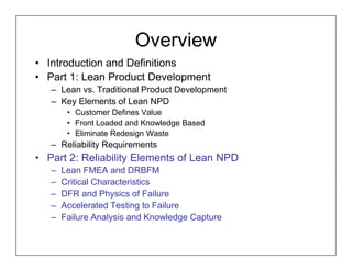
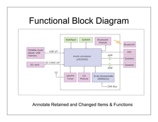
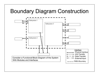
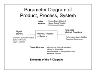
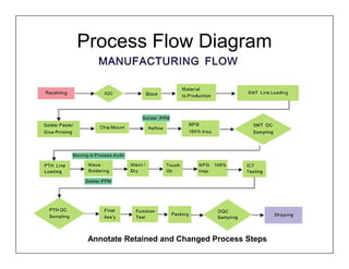
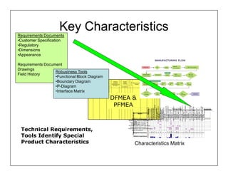
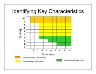
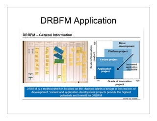
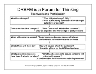

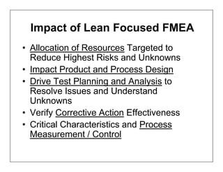
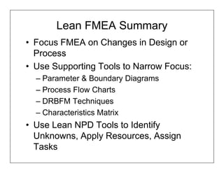
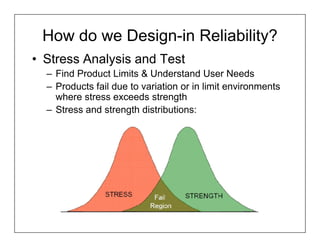


This document discusses using Failure Mode and Effects Analysis (FMEA), Design Failure Mode and Effects Analysis (DFMEA), Design for Reliability (DFR), testing, and failure analysis in lean new product development. It covers key elements of lean NPD like defining value from the customer perspective, front-loading processes with knowledge, and eliminating waste. Methods like functional block diagrams, boundary diagrams, parameter diagrams, and process flow diagrams can help focus lean FMEAs on new design elements. Characteristics critical to customer value should be identified. Accelerated testing and failure analysis capture knowledge for continuous improvement.