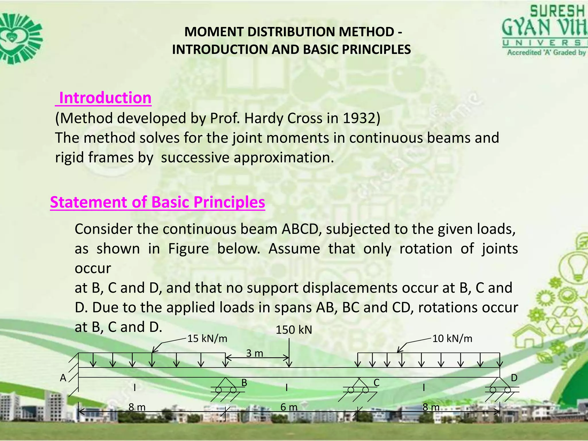
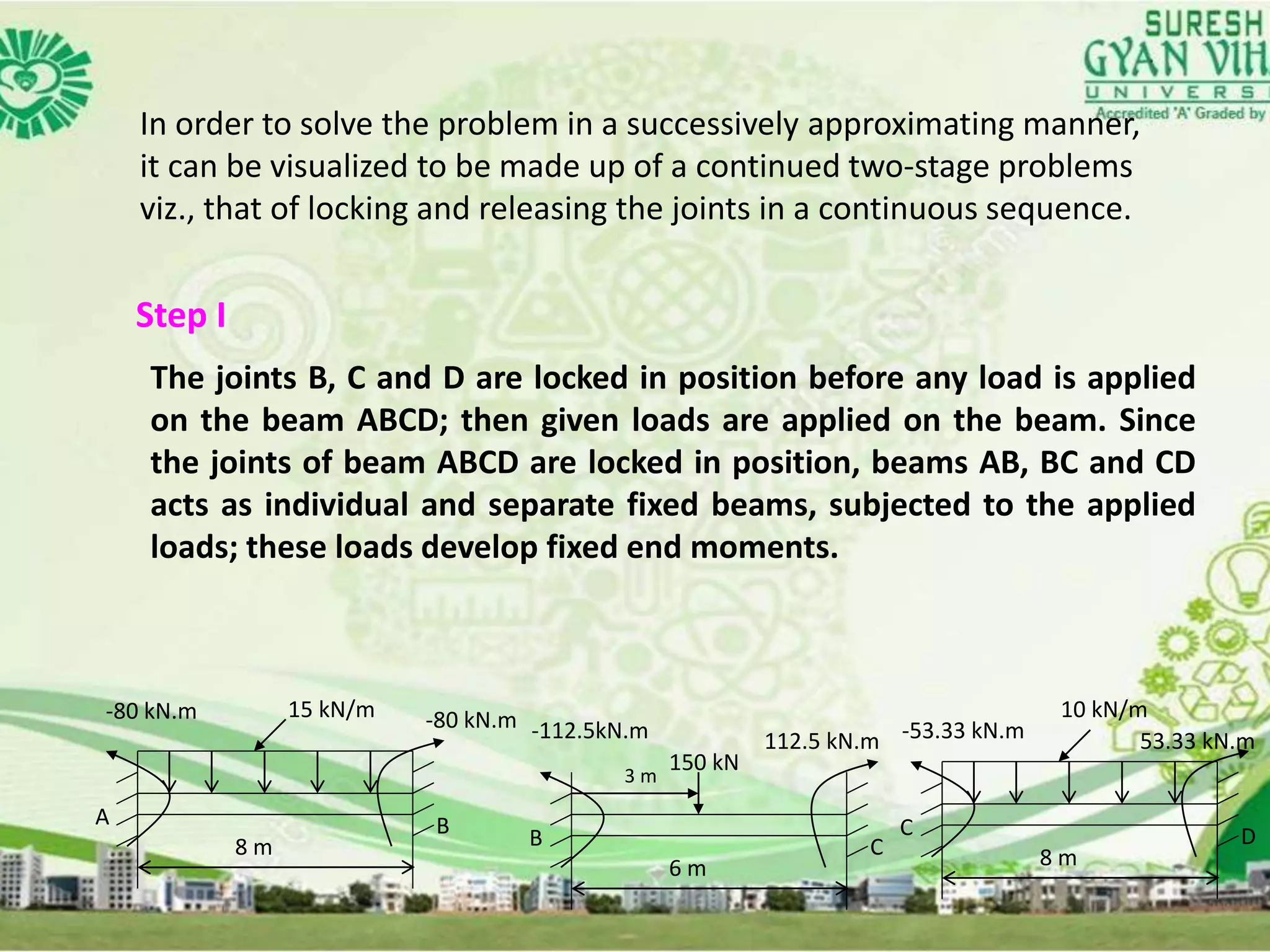
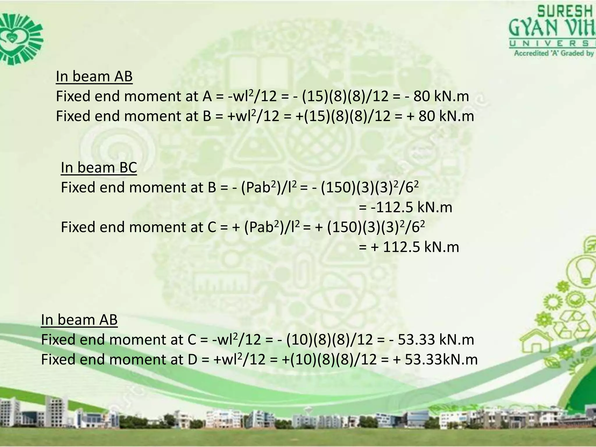
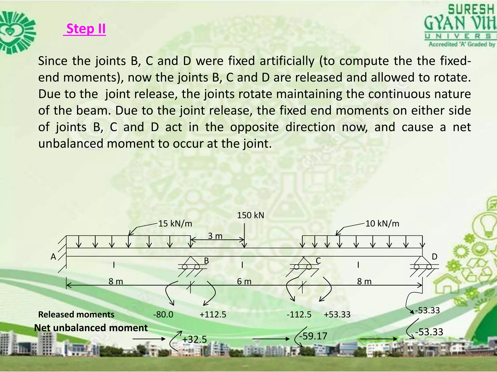
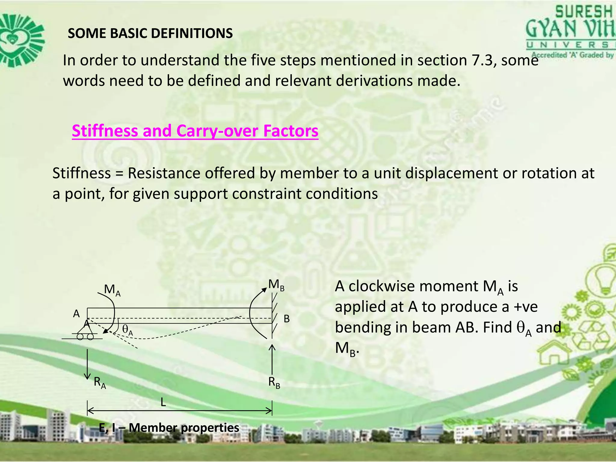
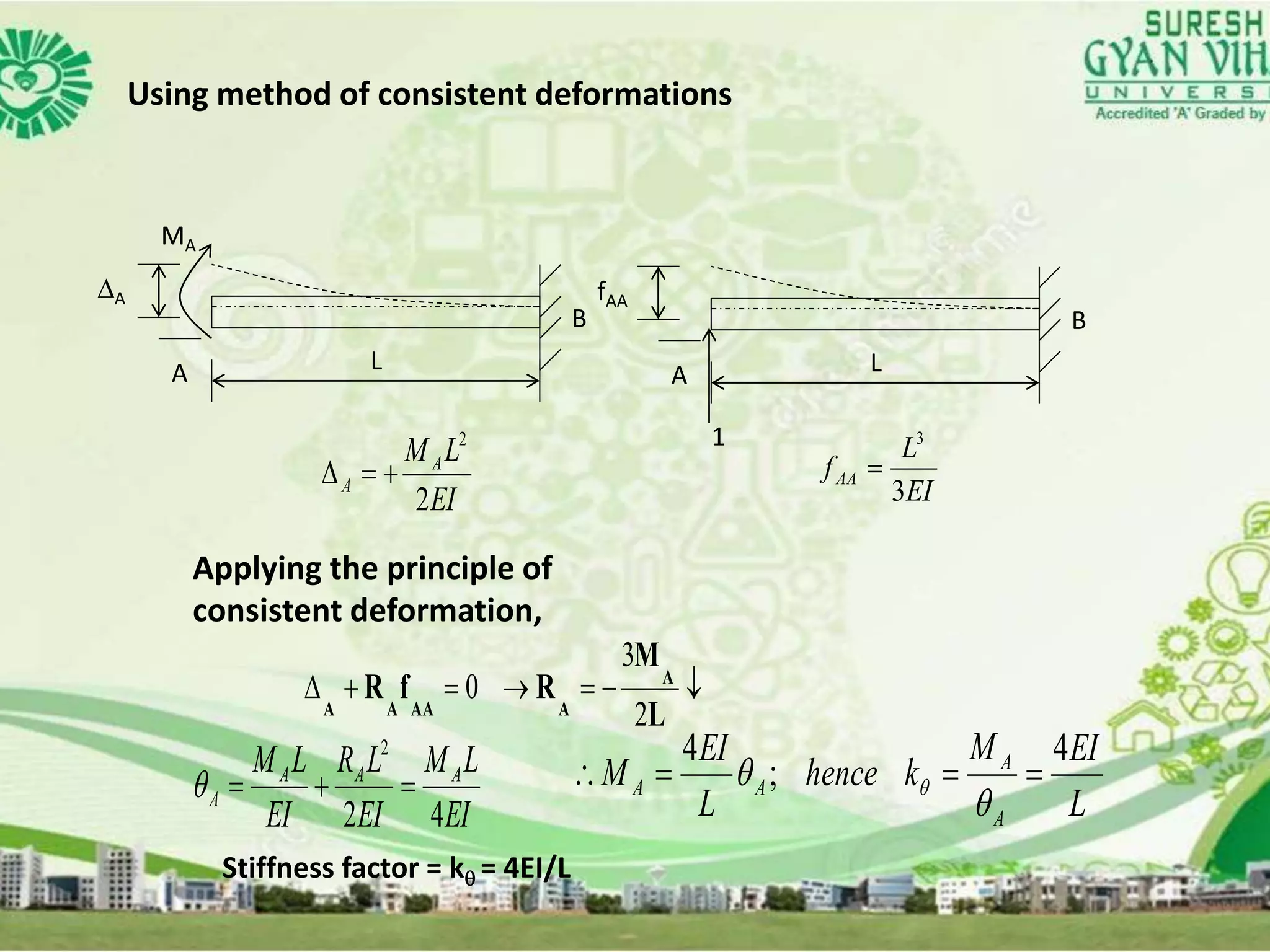
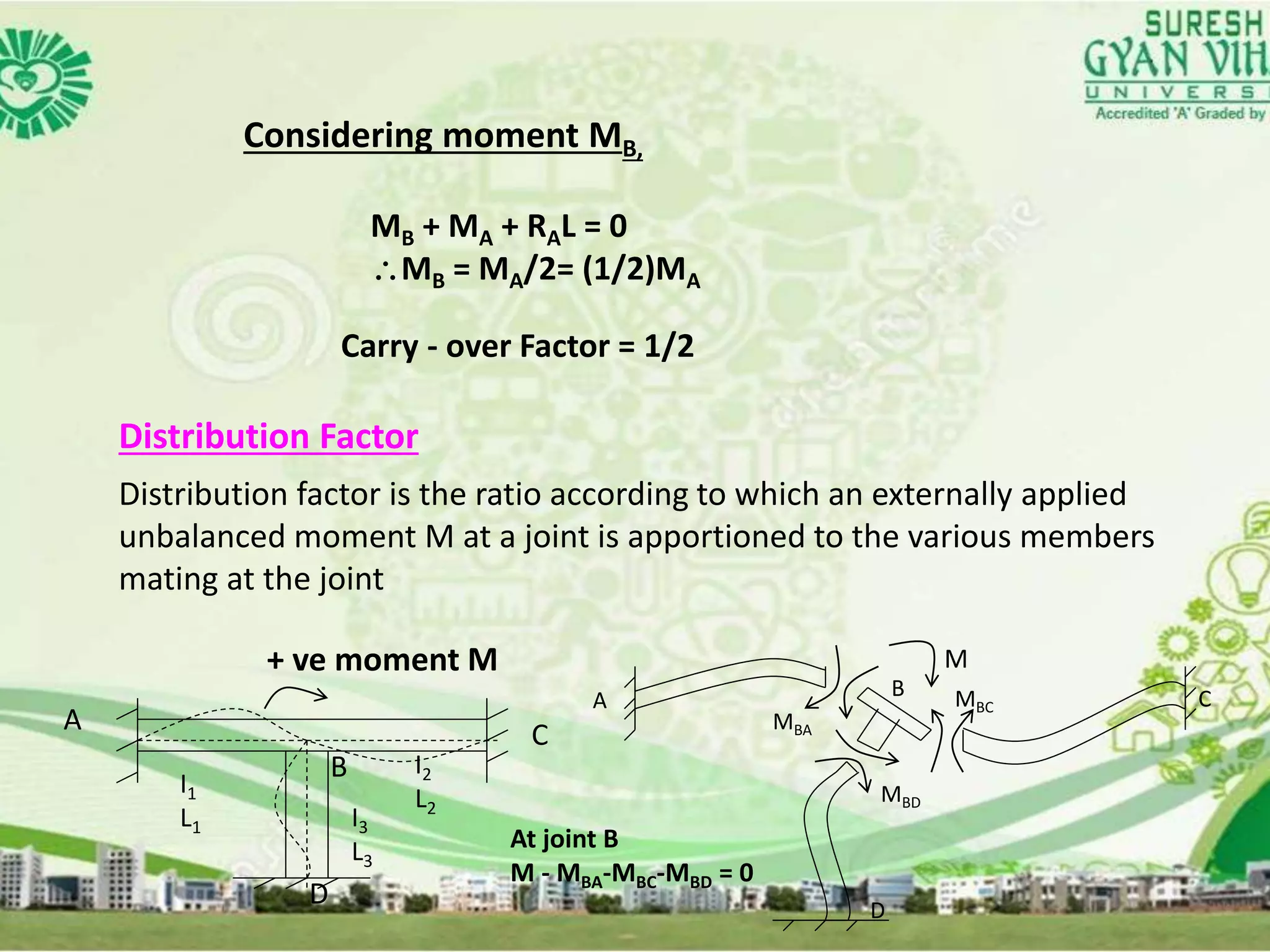
L18 analysis of indeterminate beams by moment distribution method
1. Subject Name: Theory of Structures
Topic Name:Analysis of Indeterminate Beams
by Moment Distribution Method
Lecture No: 18
Dr.Omprakash Netula
Professor & HOD
Department of Civil Engineering
9/28/2017 Lecture Number, Unit Number 1
3. MOMENT DISTRIBUTION METHOD - AN OVERVIEW
MOMENT DISTRIBUTION METHOD - AN OVERVIEW
INTRODUCTION
STATEMENT OF BASIC PRINCIPLES
SOME BASIC DEFINITIONS
SOLUTION OF PROBLEMS
MOMENT DISTRIBUTION METHOD FOR STRUCTURES
HAVING NONPRISMATIC MEMBERS
4. MOMENT DISTRIBUTION METHOD -
INTRODUCTION AND BASIC PRINCIPLES
Introduction
(Method developed by Prof. Hardy Cross in 1932)
The method solves for the joint moments in continuous beams and
rigid frames by successive approximation.
Statement of Basic Principles
Consider the continuous beam ABCD, subjected to the given loads,
as shown in Figure below. Assume that only rotation of joints
occur
at B, C and D, and that no support displacements occur at B, C and
D. Due to the applied loads in spans AB, BC and CD, rotations occur
at B, C and D.
15 kN/m 10 kN/m
150 kN
8 m 6 m 8 m
A B C D
I I I
3 m
5. In order to solve the problem in a successively approximating manner,
it can be visualized to be made up of a continued two-stage problems
viz., that of locking and releasing the joints in a continuous sequence.
Step I
The joints B, C and D are locked in position before any load is applied
on the beam ABCD; then given loads are applied on the beam. Since
the joints of beam ABCD are locked in position, beams AB, BC and CD
acts as individual and separate fixed beams, subjected to the applied
loads; these loads develop fixed end moments.
8 m
-80 kN.m -80 kN.m15 kN/m
A B
6 m
-112.5kN.m 112.5 kN.m
B C 8 m
-53.33 kN.m
10 kN/m
C D
150 kN
53.33 kN.m
3 m
6. In beam AB
Fixed end moment at A = -wl2/12 = - (15)(8)(8)/12 = - 80 kN.m
Fixed end moment at B = +wl2/12 = +(15)(8)(8)/12 = + 80 kN.m
In beam BC
Fixed end moment at B = - (Pab2)/l2 = - (150)(3)(3)2/62
= -112.5 kN.m
Fixed end moment at C = + (Pab2)/l2 = + (150)(3)(3)2/62
= + 112.5 kN.m
In beam AB
Fixed end moment at C = -wl2/12 = - (10)(8)(8)/12 = - 53.33 kN.m
Fixed end moment at D = +wl2/12 = +(10)(8)(8)/12 = + 53.33kN.m
7. Step II
Since the joints B, C and D were fixed artificially (to compute the the fixed-
end moments), now the joints B, C and D are released and allowed to rotate.
Due to the joint release, the joints rotate maintaining the continuous nature
of the beam. Due to the joint release, the fixed end moments on either side
of joints B, C and D act in the opposite direction now, and cause a net
unbalanced moment to occur at the joint.
15 kN/m 10 kN/m
8 m 6 m 8 m
A B C D
I I I
3 m
150 kN
Released moments -80.0 -112.5 +53.33 -53.33+112.5
Net unbalanced moment
+32.5 -59.17 -53.33
8. Step III
These unbalanced moments act at the joints and modify the joint moments
at B, C and D, according to their relative stiffnesses at the respective joints.
The joint moments are distributed to either side of the joint B, C or D,
according to their relative stiffnesses. These distributed moments also
modify the moments at the opposite side of the beam span, viz., at joint A in
span AB, at joints B and C in span BC and at joints C and D in span CD. This
modification is dependent on the carry-over factor (which is equal to 0.5 in
this case); when this carry over is made, the joints on opposite side are
assumed to be fixed.
Step IV
The carry-over moment becomes the unbalanced moment at the joints to
which they are carried over. Steps 3 and 4 are repeated till the carry-over
or distributed moment becomes small.
Step V
Sum up all the moments at each of the joint to obtain the joint
moments.
9. SOME BASIC DEFINITIONS
In order to understand the five steps mentioned in section 7.3, some
words need to be defined and relevant derivations made.
Stiffness and Carry-over Factors
Stiffness = Resistance offered by member to a unit displacement or rotation at
a point, for given support constraint conditions
A
MA
MB
A BA
RA RB
L
E, I – Member properties
A clockwise moment MA is
applied at A to produce a +ve
bending in beam AB. Find A and
MB.
10. Using method of consistent deformations
L
A
A
MA
B
L
fAA
A
B
1
EI
LMA
A
2
2
EI
L
fAA
3
3
Applying the principle of
consistent deformation,
L
M
RfR A
AAAAA 2
3
0
EI
LM
EI
LR
EI
LM AAA
A
42
2
L
EIM
khence
L
EI
M
A
A
AA
4
;
4
Stiffness factor = k = 4EI/L
11. Considering moment MB,
MB + MA + RAL = 0
MB = MA/2= (1/2)MA
Carry - over Factor = 1/2
Distribution Factor
Distribution factor is the ratio according to which an externally applied
unbalanced moment M at a joint is apportioned to the various members
mating at the joint
+ ve moment M
A C
B
D
A
D
B C
MBA
MBC
MBD
At joint B
M - MBA-MBC-MBD = 0
I1
L1 I3
L3
I2
L2
M