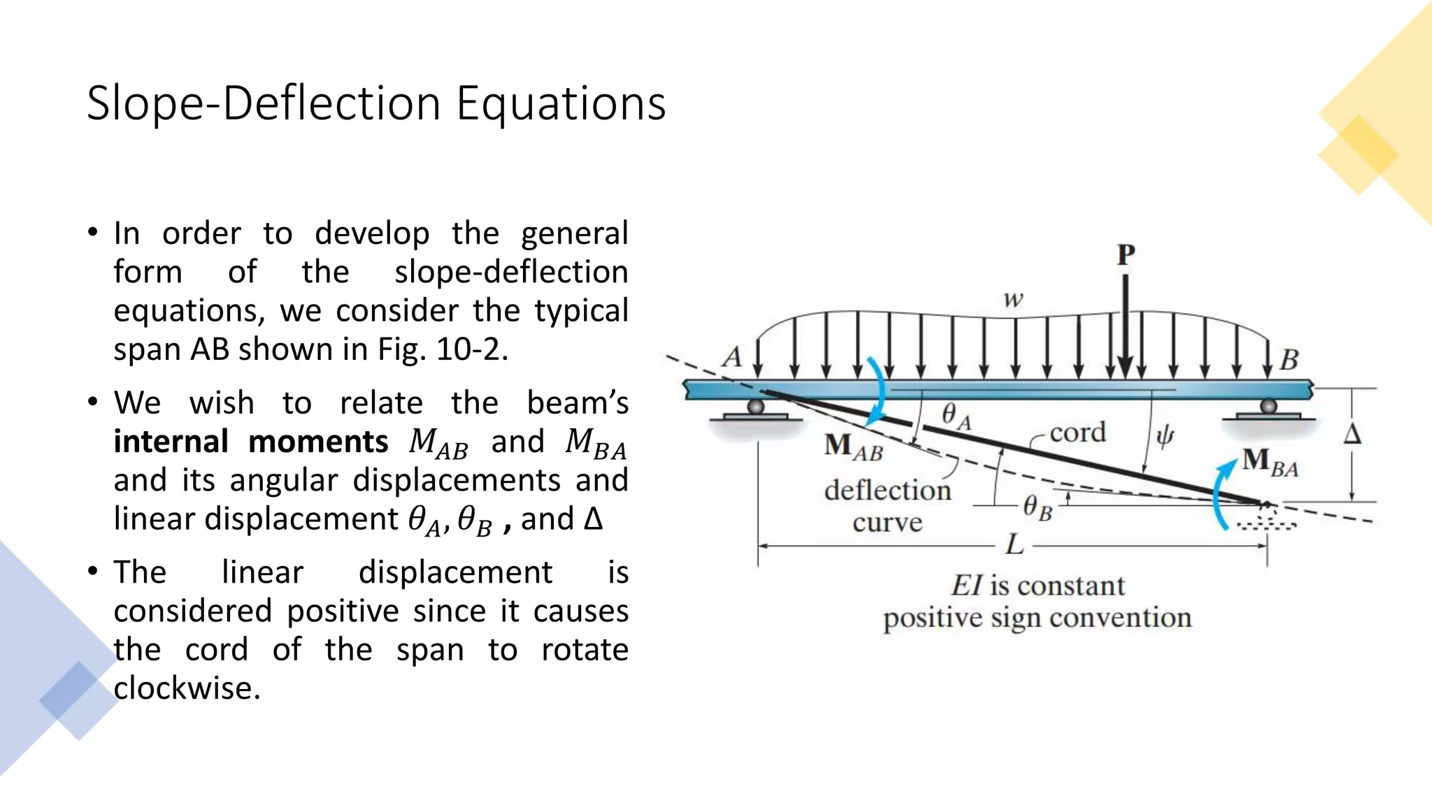
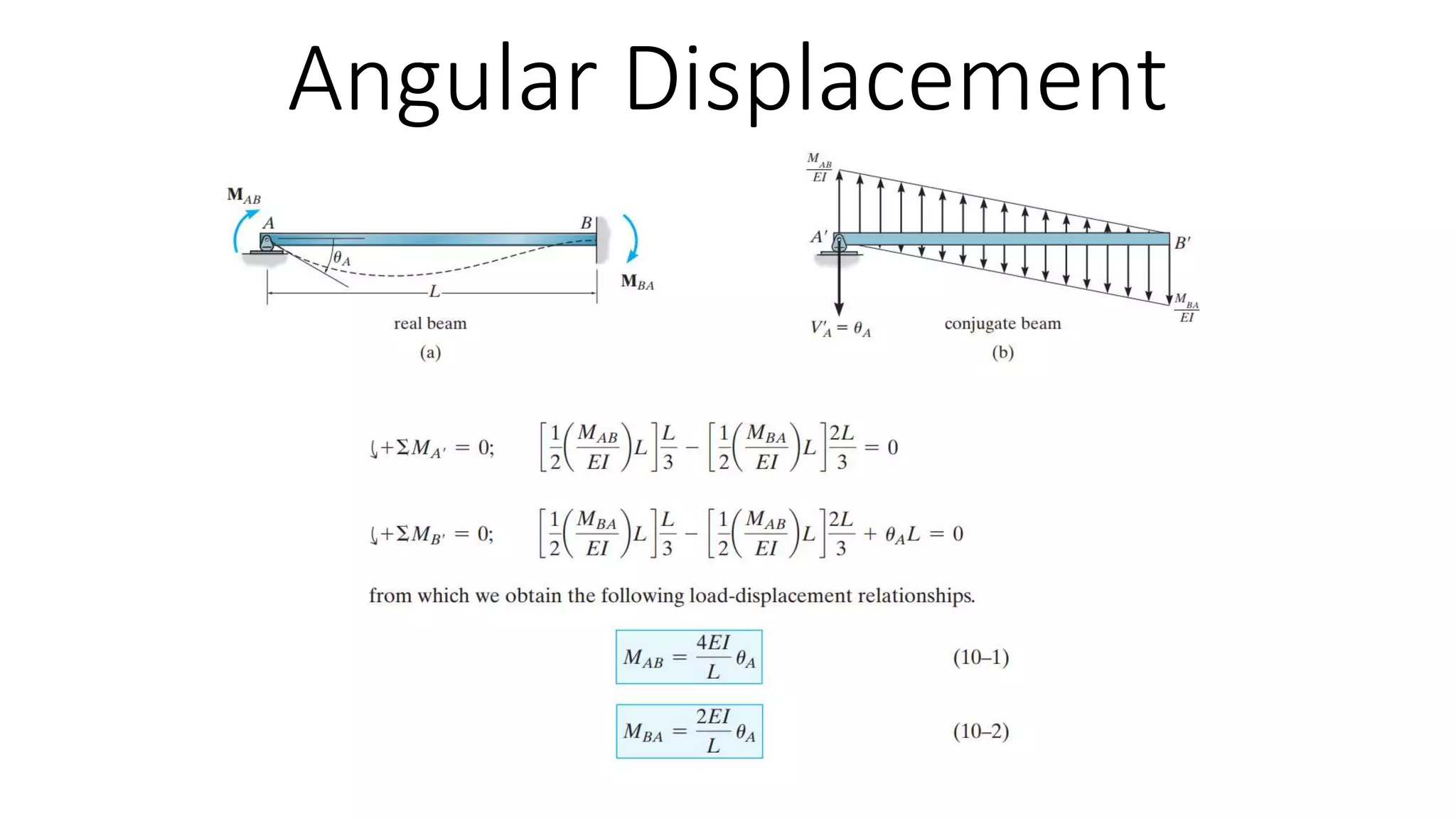
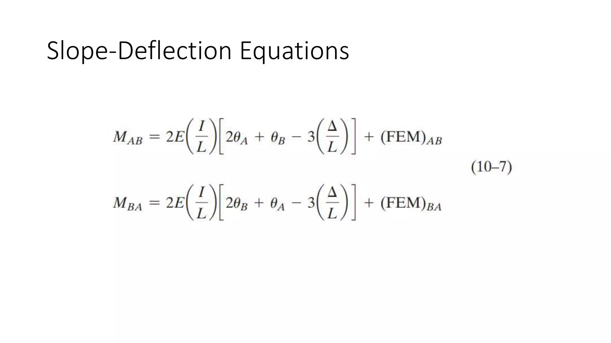
CED 426
Structural Theory II
Lecture 12
Displacement Method of Analysis: Slope Deflection Equations
Mary Joanne C. Aniñon
Instructor
Degrees of Freedom
• When a structure is loaded, specified points on it, called nodes, will
undergo unknown displacements. These displacements are referred
to as the degrees of freedom for the structure, and in displacement
method of analysis it is important to specify these degrees of
freedom since they become the unknowns when the method is
applied.
• The number of these unknowns is referred to as the degree in which
the structure is kinematically indeterminate.
Degrees of Freedom
• Nodes on a structure are usually located at joints, supports, at the
ends of a member, or where the members have a sudden change in
cross section.
• In three dimensions, each node on a frame or beam can have most
three linear displacements and three rotational displacements
• In two dimensions, each node on a frame or beam can have most two
linear displacements and two rotational displacements
Degrees of Freedom
• For the beam in Fig. 10-1a, any load P applied on the beam will cause
node A only to rotate, while node B is completely restricted from
moving. Hence the beam has only one unknown degree of freedom
𝜃𝐴, and is kinematically indeterminate to the first degree.
Degrees of Freedom
• The beam in Fig. 10-1b has nodes at A, B, and C, and so has four
degrees of freedom, designated by the unknown rotational
displacements 𝜃𝐴 , 𝜃𝐵 , 𝜃𝐶 and the vertical displacement ∆𝐶
Degrees of Freedom
• For the frame in Fig. 10-1c, the frame
has three degrees of freedom
Degrees of Freedom
• In summary, specifying the kinematic indeterminacy or the number of
unconstrained degrees of freedom for the structure is a necessary
first step when applying a displacement method of analysis.
• It identifies the number of unknowns in the problem.
• Once these nodal displacements are determined, then the
deformation of the structural members will be completely specified,
and the loadings within the member can be obtained.
Slope-Deflection Equations
• The slope-deflection method is so named since it relates the
unknown slopes and deflections to the applied load on the structure.
• The method was originally developed by Heinrich Otto Mohr for the
purpose of studying secondary stresses in trusses. Later in 1915, G.A.
Maney developed a refined version of this technique and applied it to
the analysis of indeterminate beams and framed structures
Slope-Deflection Equations
• In order to develop the general
form of the slope-deflection
equations, we consider the typical
span AB shown in Fig. 10-2.
• We wish to relate the beam’s
internal moments 𝑀𝐴𝐵 and 𝑀𝐵𝐴
and its angular displacements and
linear displacement 𝜃𝐴, 𝜃𝐵 , and ∆
• The linear displacement is
considered positive since it causes
the cord of the span to rotate
clockwise.
Angular Displacement
Relative Linear Displacement
Slope-Deflection Equations
F F
𝑀𝐴𝐵 =
2𝐸𝐼
𝐿
2𝜃𝐴 + 𝜃𝐵 −
3∆
𝐿
+ (𝐹𝐸𝑀)𝐴𝐵
Topic3_Slope Deflection Equations.pptx

Topic3_Slope Deflection Equations.pptx

  • 1.
    CED 426 Structural TheoryII Lecture 12 Displacement Method of Analysis: Slope Deflection Equations Mary Joanne C. Aniñon Instructor
  • 2.
    Degrees of Freedom •When a structure is loaded, specified points on it, called nodes, will undergo unknown displacements. These displacements are referred to as the degrees of freedom for the structure, and in displacement method of analysis it is important to specify these degrees of freedom since they become the unknowns when the method is applied. • The number of these unknowns is referred to as the degree in which the structure is kinematically indeterminate.
  • 3.
    Degrees of Freedom •Nodes on a structure are usually located at joints, supports, at the ends of a member, or where the members have a sudden change in cross section. • In three dimensions, each node on a frame or beam can have most three linear displacements and three rotational displacements • In two dimensions, each node on a frame or beam can have most two linear displacements and two rotational displacements
  • 4.
    Degrees of Freedom •For the beam in Fig. 10-1a, any load P applied on the beam will cause node A only to rotate, while node B is completely restricted from moving. Hence the beam has only one unknown degree of freedom 𝜃𝐴, and is kinematically indeterminate to the first degree.
  • 5.
    Degrees of Freedom •The beam in Fig. 10-1b has nodes at A, B, and C, and so has four degrees of freedom, designated by the unknown rotational displacements 𝜃𝐴 , 𝜃𝐵 , 𝜃𝐶 and the vertical displacement ∆𝐶
  • 6.
    Degrees of Freedom •For the frame in Fig. 10-1c, the frame has three degrees of freedom
  • 7.
    Degrees of Freedom •In summary, specifying the kinematic indeterminacy or the number of unconstrained degrees of freedom for the structure is a necessary first step when applying a displacement method of analysis. • It identifies the number of unknowns in the problem. • Once these nodal displacements are determined, then the deformation of the structural members will be completely specified, and the loadings within the member can be obtained.
  • 8.
    Slope-Deflection Equations • Theslope-deflection method is so named since it relates the unknown slopes and deflections to the applied load on the structure. • The method was originally developed by Heinrich Otto Mohr for the purpose of studying secondary stresses in trusses. Later in 1915, G.A. Maney developed a refined version of this technique and applied it to the analysis of indeterminate beams and framed structures
  • 9.
    Slope-Deflection Equations • Inorder to develop the general form of the slope-deflection equations, we consider the typical span AB shown in Fig. 10-2. • We wish to relate the beam’s internal moments 𝑀𝐴𝐵 and 𝑀𝐵𝐴 and its angular displacements and linear displacement 𝜃𝐴, 𝜃𝐵 , and ∆ • The linear displacement is considered positive since it causes the cord of the span to rotate clockwise.
  • 10.
  • 11.
  • 12.
  • 13.
    Slope-Deflection Equations F F 𝑀𝐴𝐵= 2𝐸𝐼 𝐿 2𝜃𝐴 + 𝜃𝐵 − 3∆ 𝐿 + (𝐹𝐸𝑀)𝐴𝐵