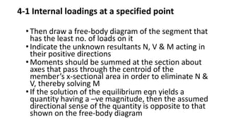
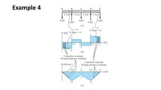
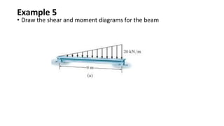
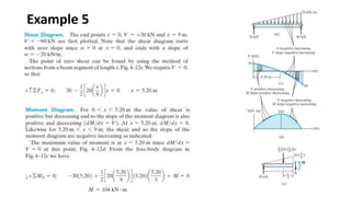
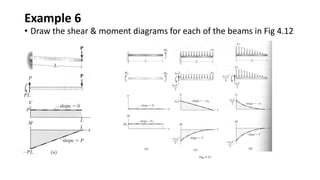
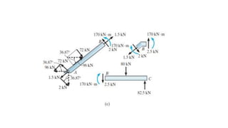
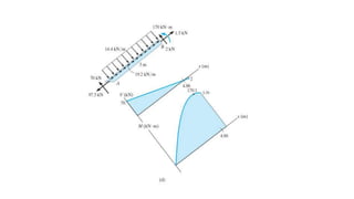
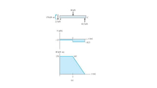
The document discusses methods for determining internal forces like shear, moment and normal force in structural members. It describes:
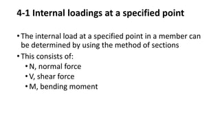
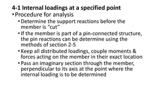
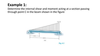
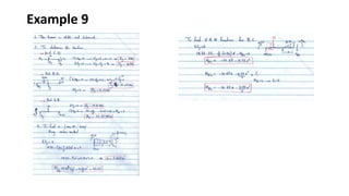
1) Using a method of sections to determine internal forces at a specified point by analyzing the external loads and support reactions.
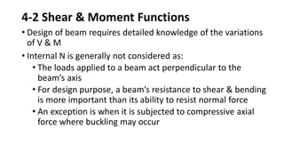
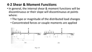
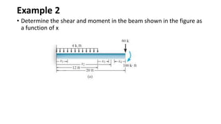
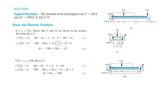
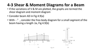
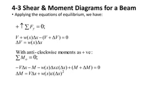
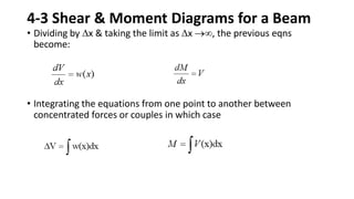
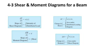
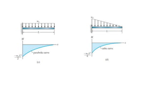
2) Shear and moment functions vary across a member depending on the type and location of loads. They can be determined by drawing free body diagrams of small segments.
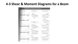
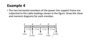
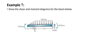
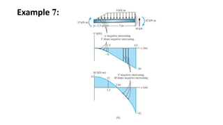
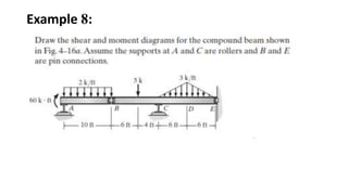
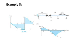
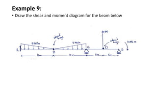
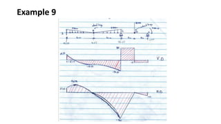
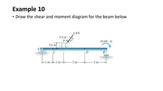
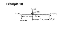
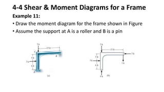
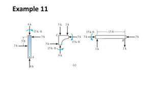
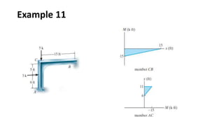
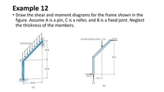
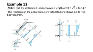
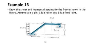
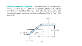
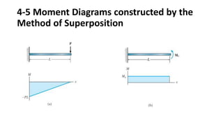
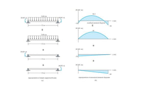
3) Shear and moment diagrams are created by plotting the variation of shear and moment across a member. Examples show how to construct these diagrams for beams and frames.