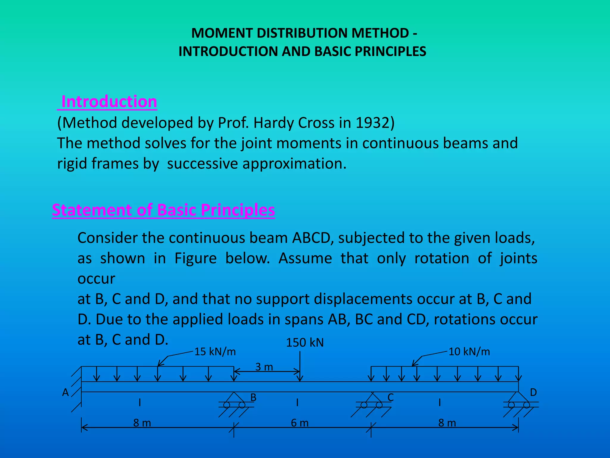
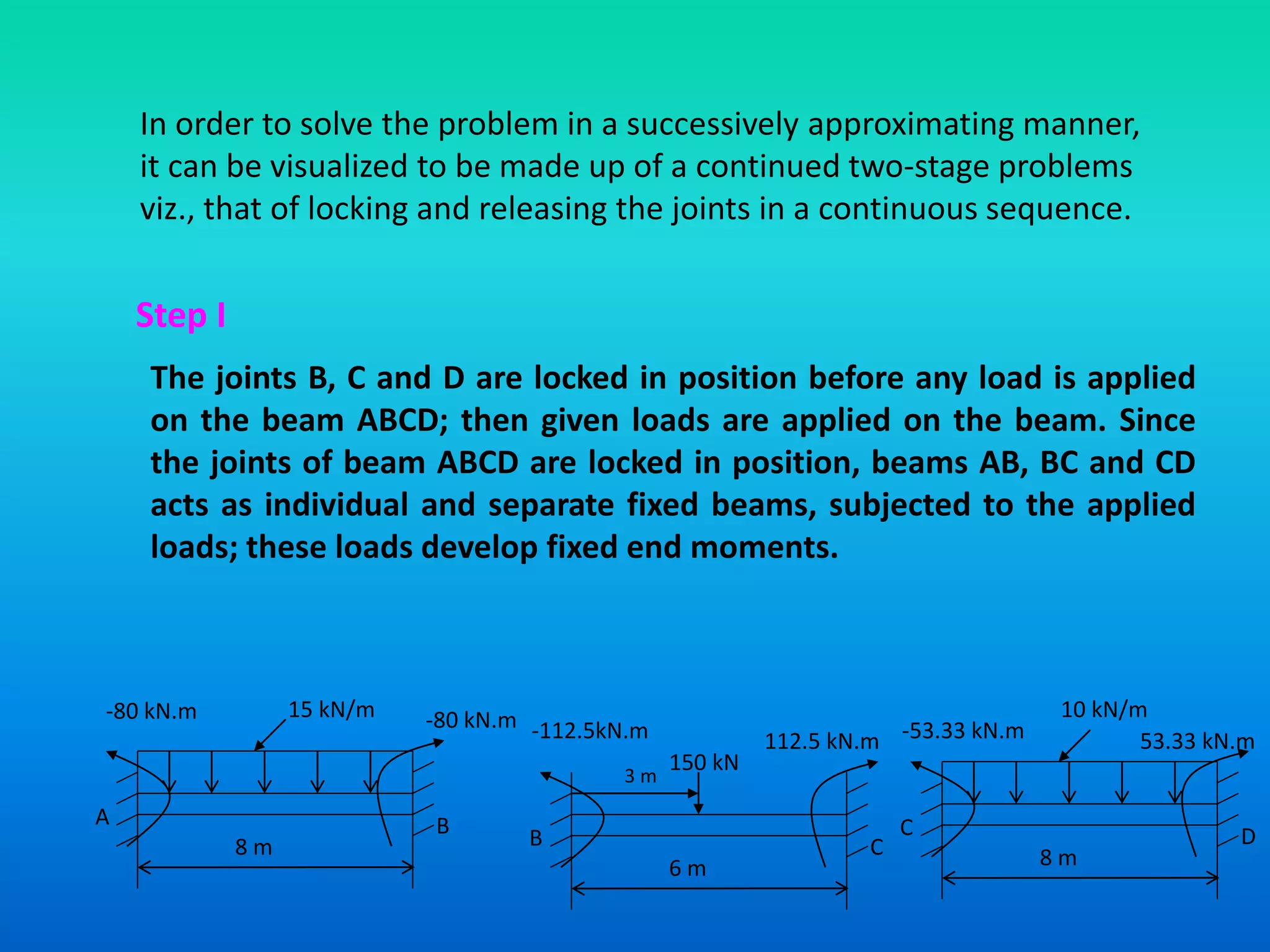
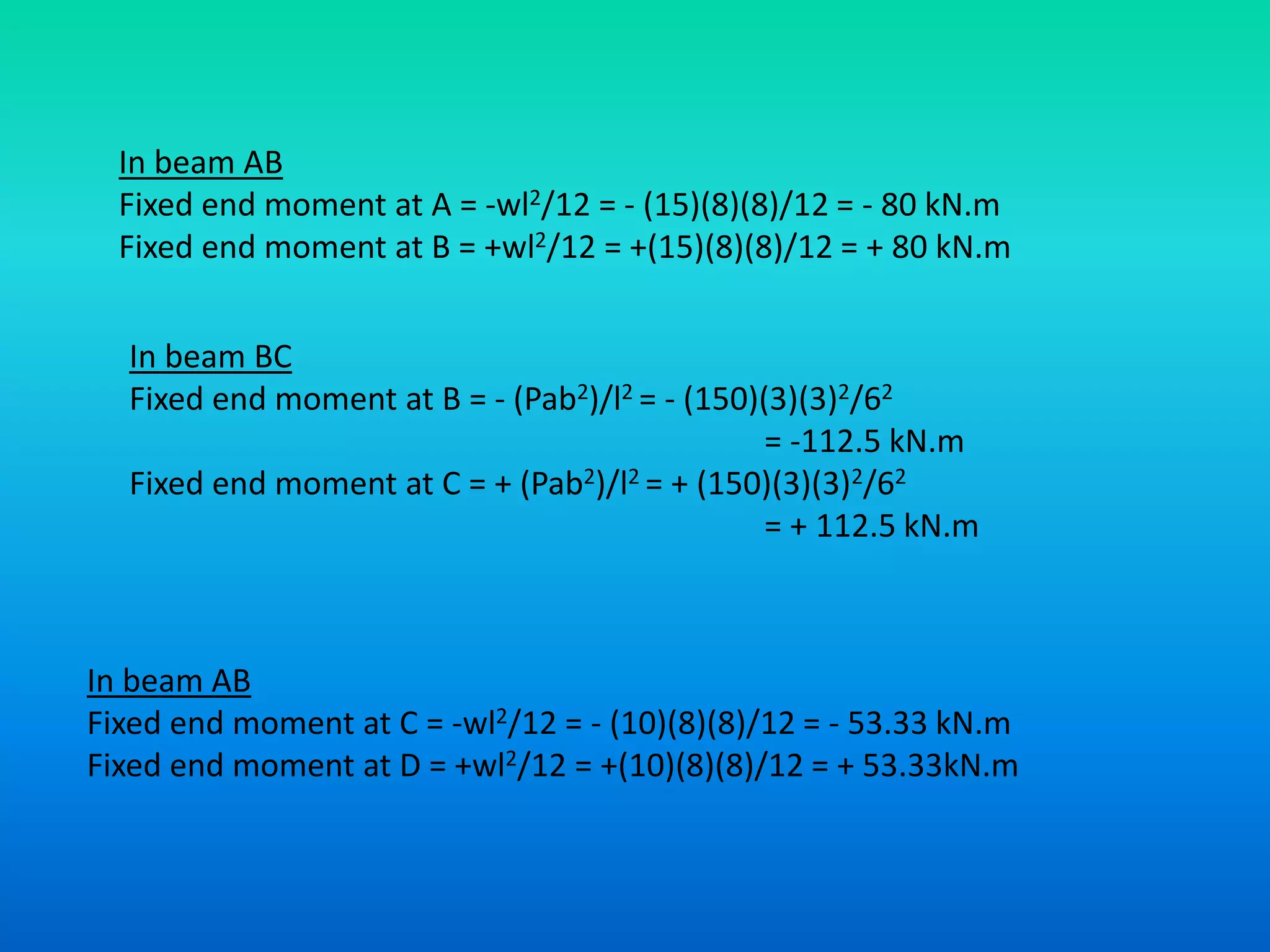
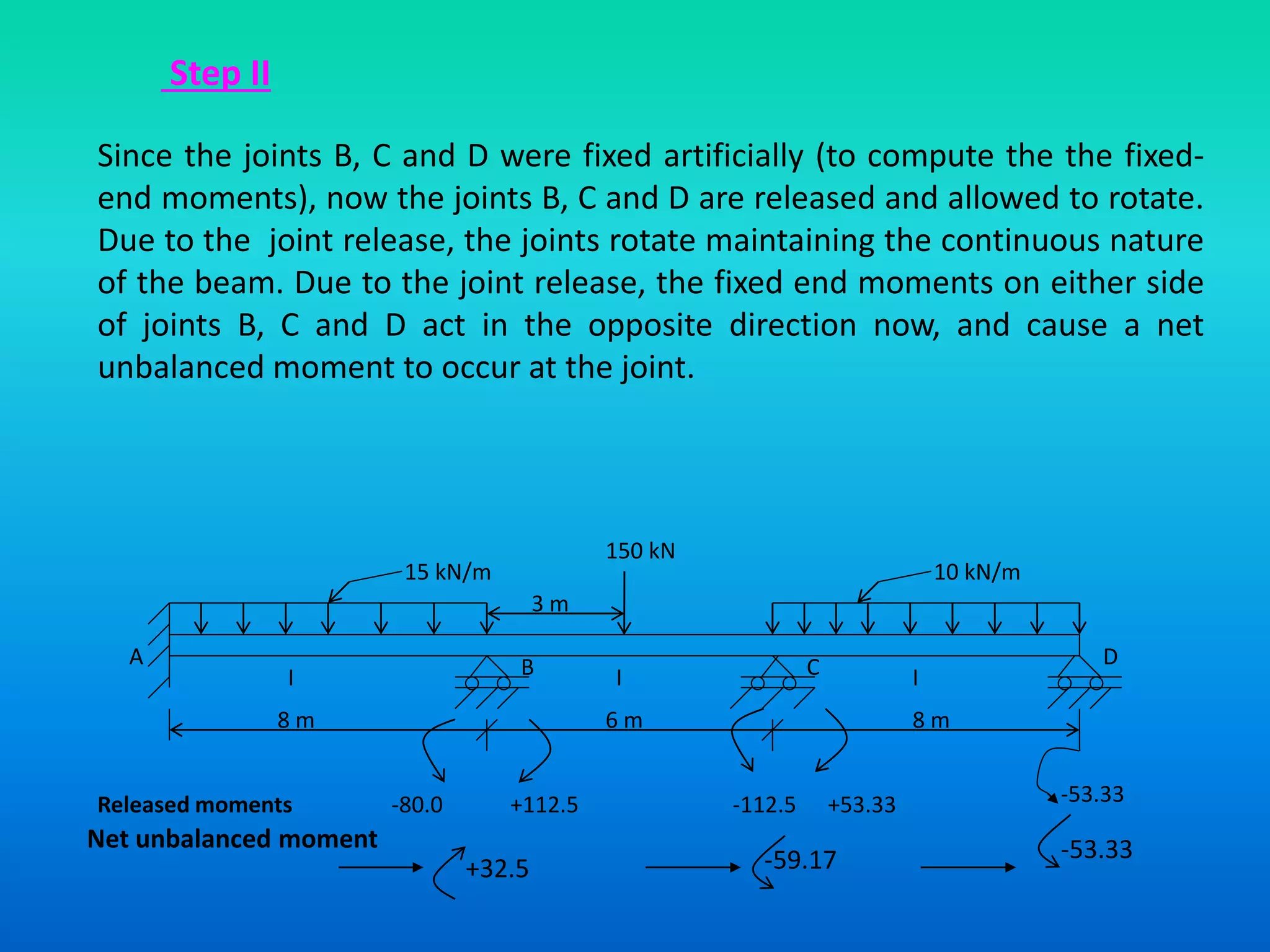
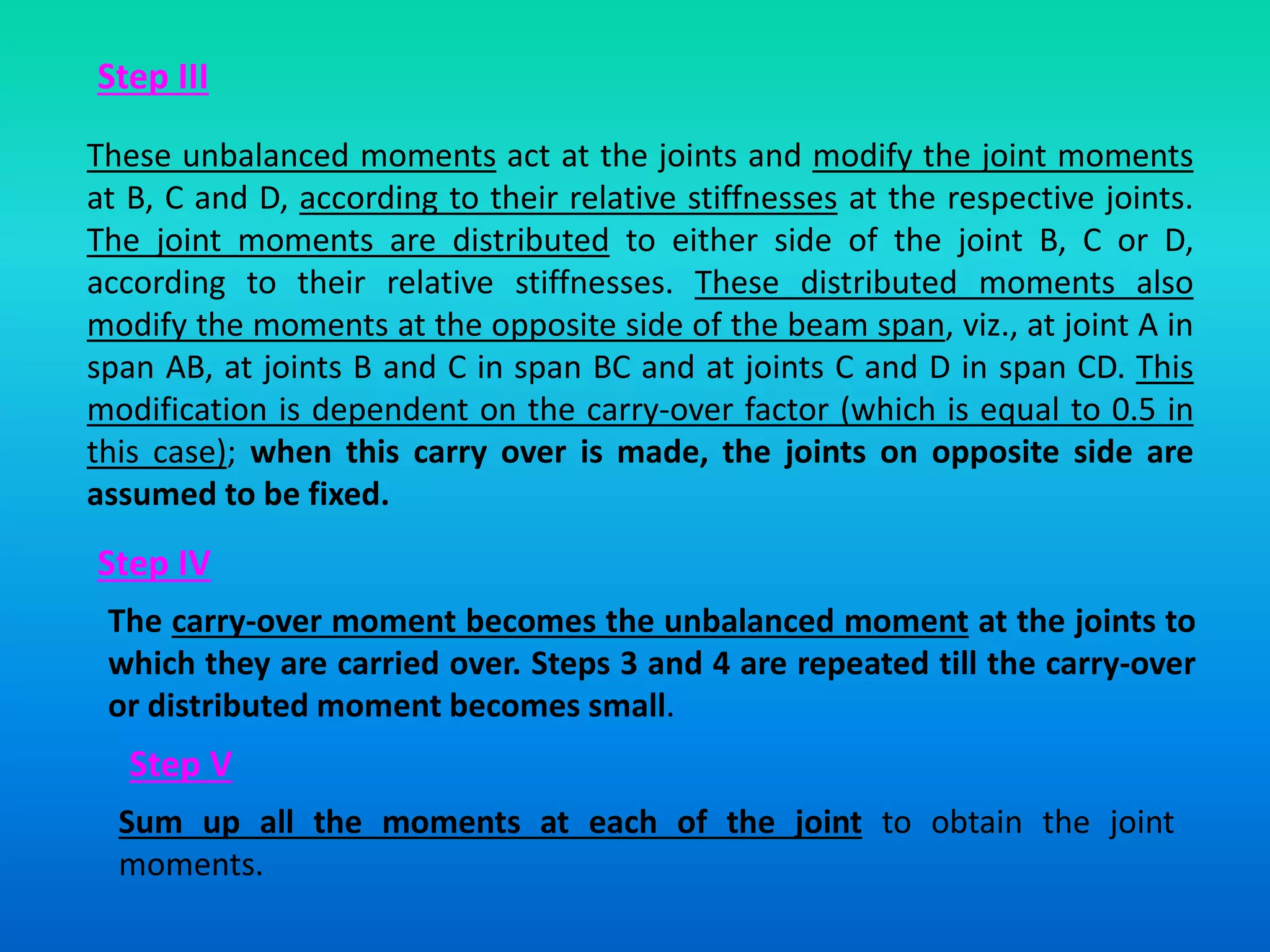
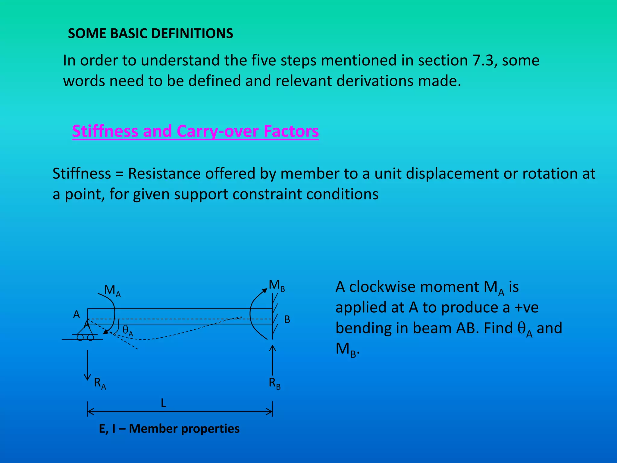
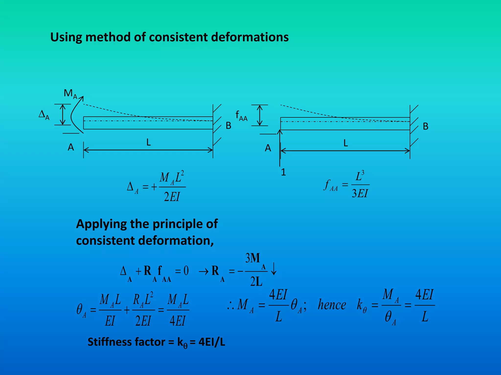
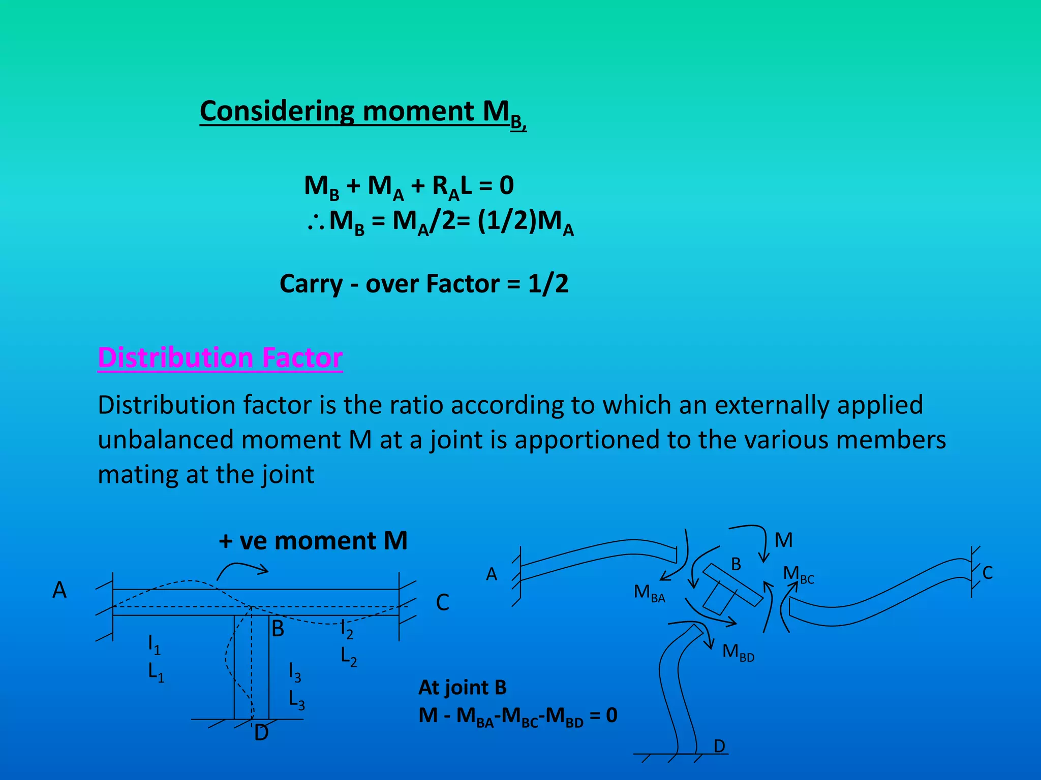
SlideShare a Scribd company logo
Analysis of Indeterminate Beams by
MOMENT DISTRIBUTION METHOD
MOMENT DISTRIBUTION METHOD - AN OVERVIEW
 MOMENT DISTRIBUTION METHOD - AN OVERVIEW
 INTRODUCTION
 STATEMENT OF BASIC PRINCIPLES
 SOME BASIC DEFINITIONS
 SOLUTION OF PROBLEMS
 MOMENT DISTRIBUTION METHOD FOR STRUCTURES
HAVING NONPRISMATIC MEMBERS
MOMENT DISTRIBUTION METHOD -
INTRODUCTION AND BASIC PRINCIPLES
Introduction
(Method developed by Prof. Hardy Cross in 1932)
The method solves for the joint moments in continuous beams and
rigid frames by successive approximation.
Statement of Basic Principles
Consider the continuous beam ABCD, subjected to the given loads,
as shown in Figure below. Assume that only rotation of joints
occur
at B, C and D, and that no support displacements occur at B, C and
D. Due to the applied loads in spans AB, BC and CD, rotations occur
at B, C and D.
15 kN/m 10 kN/m
150 kN
8 m 6 m 8 m
A B C D
I I I
3 m
In order to solve the problem in a successively approximating manner,
it can be visualized to be made up of a continued two-stage problems
viz., that of locking and releasing the joints in a continuous sequence.
Step I
The joints B, C and D are locked in position before any load is applied
on the beam ABCD; then given loads are applied on the beam. Since
the joints of beam ABCD are locked in position, beams AB, BC and CD
acts as individual and separate fixed beams, subjected to the applied
loads; these loads develop fixed end moments.
8 m
-80 kN.m -80 kN.m15 kN/m
A B
6 m
-112.5kN.m 112.5 kN.m
B C 8 m
-53.33 kN.m
10 kN/m
C D
150 kN
53.33 kN.m
3 m
In beam AB
Fixed end moment at A = -wl2/12 = - (15)(8)(8)/12 = - 80 kN.m
Fixed end moment at B = +wl2/12 = +(15)(8)(8)/12 = + 80 kN.m
In beam BC
Fixed end moment at B = - (Pab2)/l2 = - (150)(3)(3)2/62
= -112.5 kN.m
Fixed end moment at C = + (Pab2)/l2 = + (150)(3)(3)2/62
= + 112.5 kN.m
In beam AB
Fixed end moment at C = -wl2/12 = - (10)(8)(8)/12 = - 53.33 kN.m
Fixed end moment at D = +wl2/12 = +(10)(8)(8)/12 = + 53.33kN.m
Step II
Since the joints B, C and D were fixed artificially (to compute the the fixed-
end moments), now the joints B, C and D are released and allowed to rotate.
Due to the joint release, the joints rotate maintaining the continuous nature
of the beam. Due to the joint release, the fixed end moments on either side
of joints B, C and D act in the opposite direction now, and cause a net
unbalanced moment to occur at the joint.
15 kN/m 10 kN/m
8 m 6 m 8 m
A B C D
I I I
3 m
150 kN
Released moments -80.0 -112.5 +53.33 -53.33+112.5
Net unbalanced moment
+32.5 -59.17 -53.33
Step III
These unbalanced moments act at the joints and modify the joint moments
at B, C and D, according to their relative stiffnesses at the respective joints.
The joint moments are distributed to either side of the joint B, C or D,
according to their relative stiffnesses. These distributed moments also
modify the moments at the opposite side of the beam span, viz., at joint A in
span AB, at joints B and C in span BC and at joints C and D in span CD. This
modification is dependent on the carry-over factor (which is equal to 0.5 in
this case); when this carry over is made, the joints on opposite side are
assumed to be fixed.
Step IV
The carry-over moment becomes the unbalanced moment at the joints to
which they are carried over. Steps 3 and 4 are repeated till the carry-over
or distributed moment becomes small.
Step V
Sum up all the moments at each of the joint to obtain the joint
moments.
SOME BASIC DEFINITIONS
In order to understand the five steps mentioned in section 7.3, some
words need to be defined and relevant derivations made.
Stiffness and Carry-over Factors
Stiffness = Resistance offered by member to a unit displacement or rotation at
a point, for given support constraint conditions
A
MA
MB
A BA
RA RB
L
E, I – Member properties
A clockwise moment MA is
applied at A to produce a +ve
bending in beam AB. Find A and
MB.
Using method of consistent deformations
L
A
A
MA
B
L
fAA
A
B
1
EI
LMA
A
2
2
 EI
L
fAA
3
3

Applying the principle of
consistent deformation,

L
M
RfR A
AAAAA 2
3
0
EI
LM
EI
LR
EI
LM AAA
A
42
2
 L
EIM
khence
L
EI
M
A
A
AA
4
;
4


 
Stiffness factor = k = 4EI/L
Considering moment MB,
MB + MA + RAL = 0
MB = MA/2= (1/2)MA
Carry - over Factor = 1/2
Distribution Factor
Distribution factor is the ratio according to which an externally applied
unbalanced moment M at a joint is apportioned to the various members
mating at the joint
+ ve moment M
A C
B
D
A
D
B C
MBA
MBC
MBD
At joint B
M - MBA-MBC-MBD = 0
I1
L1 I3
L3
I2
L2
M

More Related Content

What's hot

Determinate structures
 Determinate structures Determinate structures
Determinate structures
Tarun Gehlot
 
Solving statically indeterminate structure slope deflection 10.01.03.019
Solving statically indeterminate structure slope deflection   10.01.03.019Solving statically indeterminate structure slope deflection   10.01.03.019
Solving statically indeterminate structure slope deflection 10.01.03.019
Faris Imam
 

What's hot (20)

Slope deflection method
Slope deflection methodSlope deflection method
Slope deflection method
 
78
7878
78
 
Analysis of statically indeterminate structures
Analysis of statically indeterminate structuresAnalysis of statically indeterminate structures
Analysis of statically indeterminate structures
 
Lecture 1 (Introduction to Structural Analysis II)
Lecture  1 (Introduction to Structural Analysis II)Lecture  1 (Introduction to Structural Analysis II)
Lecture 1 (Introduction to Structural Analysis II)
 
Module2 rajesh sir
Module2 rajesh sirModule2 rajesh sir
Module2 rajesh sir
 
L15: Analysis of Indeterminate Beams by Slope Deflection Method
L15: Analysis of Indeterminate Beams by Slope Deflection Method L15: Analysis of Indeterminate Beams by Slope Deflection Method
L15: Analysis of Indeterminate Beams by Slope Deflection Method
 
Equilibrium 3
Equilibrium 3Equilibrium 3
Equilibrium 3
 
Statically indeterminate beam moment distribution method
Statically indeterminate beam moment distribution methodStatically indeterminate beam moment distribution method
Statically indeterminate beam moment distribution method
 
Mba admission in india
Mba admission in indiaMba admission in india
Mba admission in india
 
Slope deflection method
Slope deflection methodSlope deflection method
Slope deflection method
 
Determinate structures
 Determinate structures Determinate structures
Determinate structures
 
Chapter 19(statically indeterminate beams continuous beams)
Chapter 19(statically indeterminate beams continuous beams)Chapter 19(statically indeterminate beams continuous beams)
Chapter 19(statically indeterminate beams continuous beams)
 
Analysis of indeterminate beam by slopeand deflection method
Analysis of indeterminate beam by slopeand deflection methodAnalysis of indeterminate beam by slopeand deflection method
Analysis of indeterminate beam by slopeand deflection method
 
Deformation of structures
Deformation of structuresDeformation of structures
Deformation of structures
 
Top schools in delhi ncr
Top schools in delhi ncrTop schools in delhi ncr
Top schools in delhi ncr
 
ANALYSIS OF FRAMES USING SLOPE DEFLECTION METHOD
ANALYSIS OF FRAMES USING SLOPE DEFLECTION METHODANALYSIS OF FRAMES USING SLOPE DEFLECTION METHOD
ANALYSIS OF FRAMES USING SLOPE DEFLECTION METHOD
 
Moment Distribution Method SA-2
Moment Distribution Method SA-2Moment Distribution Method SA-2
Moment Distribution Method SA-2
 
Three moment theorem
Three moment theoremThree moment theorem
Three moment theorem
 
Solving statically indeterminate structure slope deflection 10.01.03.019
Solving statically indeterminate structure slope deflection   10.01.03.019Solving statically indeterminate structure slope deflection   10.01.03.019
Solving statically indeterminate structure slope deflection 10.01.03.019
 
Aircraft Structures for Engineering Students 5th Edition Megson Solutions Manual
Aircraft Structures for Engineering Students 5th Edition Megson Solutions ManualAircraft Structures for Engineering Students 5th Edition Megson Solutions Manual
Aircraft Structures for Engineering Students 5th Edition Megson Solutions Manual
 

Similar to L15 analysis of indeterminate beams by moment distribution method

Relative velocity
Relative velocityRelative velocity
Relative velocity
indrasir
 
Relative velocity
Relative velocityRelative velocity
Relative velocity
indrasir
 
02 determinate structures
02 determinate structures02 determinate structures
02 determinate structures
ELIMENG
 

Similar to L15 analysis of indeterminate beams by moment distribution method (20)

Admission in india 2014
Admission in india 2014Admission in india 2014
Admission in india 2014
 
Strength of materials_by_r_s_khurmi-601-700
Strength of materials_by_r_s_khurmi-601-700Strength of materials_by_r_s_khurmi-601-700
Strength of materials_by_r_s_khurmi-601-700
 
Moment distribution
Moment distributionMoment distribution
Moment distribution
 
Def numerical
Def numericalDef numerical
Def numerical
 
Topic4_Moment Distribution with Stiffness Factor Modification.pptx
Topic4_Moment Distribution with Stiffness Factor Modification.pptxTopic4_Moment Distribution with Stiffness Factor Modification.pptx
Topic4_Moment Distribution with Stiffness Factor Modification.pptx
 
Mechanics.
Mechanics. Mechanics.
Mechanics.
 
Mechanics.ppt
Mechanics.pptMechanics.ppt
Mechanics.ppt
 
Topic3_Displacement Method of Analysis Frames Sideway.pptx
Topic3_Displacement Method of Analysis Frames Sideway.pptxTopic3_Displacement Method of Analysis Frames Sideway.pptx
Topic3_Displacement Method of Analysis Frames Sideway.pptx
 
Lec13 solved example
Lec13 solved exampleLec13 solved example
Lec13 solved example
 
FIXED BEAMS AND ARCH SYSTEM.pdf
FIXED BEAMS AND ARCH SYSTEM.pdfFIXED BEAMS AND ARCH SYSTEM.pdf
FIXED BEAMS AND ARCH SYSTEM.pdf
 
Topic3_Displacement Method of Analysis Frames_No-Sideway.pptx
Topic3_Displacement Method of Analysis Frames_No-Sideway.pptxTopic3_Displacement Method of Analysis Frames_No-Sideway.pptx
Topic3_Displacement Method of Analysis Frames_No-Sideway.pptx
 
Relative velocity
Relative velocityRelative velocity
Relative velocity
 
Relative velocity
Relative velocityRelative velocity
Relative velocity
 
Shear Force and Bending moment Diagram
Shear Force and Bending moment DiagramShear Force and Bending moment Diagram
Shear Force and Bending moment Diagram
 
Analysis of non sway frame portal frames by slopeand deflection method
Analysis of non sway frame portal frames by slopeand deflection methodAnalysis of non sway frame portal frames by slopeand deflection method
Analysis of non sway frame portal frames by slopeand deflection method
 
SFD & BMD Shear Force & Bending Moment Diagram
SFD & BMD Shear Force & Bending Moment DiagramSFD & BMD Shear Force & Bending Moment Diagram
SFD & BMD Shear Force & Bending Moment Diagram
 
02 determinate structures
02 determinate structures02 determinate structures
02 determinate structures
 
Topic4_Moment Distribution Frames with Sideway.pptx
Topic4_Moment Distribution Frames with Sideway.pptxTopic4_Moment Distribution Frames with Sideway.pptx
Topic4_Moment Distribution Frames with Sideway.pptx
 
Obstaclesinchaining 170811123641
Obstaclesinchaining 170811123641Obstaclesinchaining 170811123641
Obstaclesinchaining 170811123641
 
unit 1 part 2 mechanics as AKTU syllabus first yr 2021
unit 1 part 2 mechanics as AKTU syllabus first yr 2021unit 1 part 2 mechanics as AKTU syllabus first yr 2021
unit 1 part 2 mechanics as AKTU syllabus first yr 2021
 

More from Dr. OmPrakash

More from Dr. OmPrakash (20)

L34 multistorey building
L34 multistorey buildingL34 multistorey building
L34 multistorey building
 
L30 Strain energy
L30 Strain energy L30 Strain energy
L30 Strain energy
 
L25 ppt conjugate
L25 ppt conjugateL25 ppt conjugate
L25 ppt conjugate
 
L24 Numerical on Moment of Distribution Method
L24 Numerical on Moment of Distribution MethodL24 Numerical on Moment of Distribution Method
L24 Numerical on Moment of Distribution Method
 
L23 overview of slope deflection method
L23 overview of slope deflection methodL23 overview of slope deflection method
L23 overview of slope deflection method
 
L17 : Analysis of Indeterminate
L17 : Analysis of Indeterminate L17 : Analysis of Indeterminate
L17 : Analysis of Indeterminate
 
L16 : Slope Deflection Method for Analysis of Indeterminate Beams
L16 : Slope Deflection Method for Analysis of Indeterminate Beams L16 : Slope Deflection Method for Analysis of Indeterminate Beams
L16 : Slope Deflection Method for Analysis of Indeterminate Beams
 
L11 slope deflection method (1)
L11  slope deflection method (1)L11  slope deflection method (1)
L11 slope deflection method (1)
 
L10
L10L10
L10
 
L9 conjugate beam method
L9  conjugate beam methodL9  conjugate beam method
L9 conjugate beam method
 
L8 analysis of beams
L8 analysis of beamsL8 analysis of beams
L8 analysis of beams
 
L7
L7L7
L7
 
L6 analysis by moment area theorems
L6  analysis by moment area theoremsL6  analysis by moment area theorems
L6 analysis by moment area theorems
 
L5
L5L5
L5
 
L5
L5L5
L5
 
L4 degree of redundancy of space truss
L4 degree of redundancy of space trussL4 degree of redundancy of space truss
L4 degree of redundancy of space truss
 
L1
L1L1
L1
 
L3 degree of redundancy of plane frames
L3 degree of redundancy of plane framesL3 degree of redundancy of plane frames
L3 degree of redundancy of plane frames
 
L1
L1L1
L1
 
L10 slope deflection method for the analysis of indeterminate
L10 slope deflection method for the analysis of indeterminateL10 slope deflection method for the analysis of indeterminate
L10 slope deflection method for the analysis of indeterminate
 

Recently uploaded

Essentials of Automations: Optimizing FME Workflows with Parameters
Essentials of Automations: Optimizing FME Workflows with ParametersEssentials of Automations: Optimizing FME Workflows with Parameters
Essentials of Automations: Optimizing FME Workflows with Parameters
Safe Software
 

Recently uploaded (20)

Quantum Computing: Current Landscape and the Future Role of APIs
Quantum Computing: Current Landscape and the Future Role of APIsQuantum Computing: Current Landscape and the Future Role of APIs
Quantum Computing: Current Landscape and the Future Role of APIs
 
From Siloed Products to Connected Ecosystem: Building a Sustainable and Scala...
From Siloed Products to Connected Ecosystem: Building a Sustainable and Scala...From Siloed Products to Connected Ecosystem: Building a Sustainable and Scala...
From Siloed Products to Connected Ecosystem: Building a Sustainable and Scala...
 
To Graph or Not to Graph Knowledge Graph Architectures and LLMs
To Graph or Not to Graph Knowledge Graph Architectures and LLMsTo Graph or Not to Graph Knowledge Graph Architectures and LLMs
To Graph or Not to Graph Knowledge Graph Architectures and LLMs
 
From Daily Decisions to Bottom Line: Connecting Product Work to Revenue by VP...
From Daily Decisions to Bottom Line: Connecting Product Work to Revenue by VP...From Daily Decisions to Bottom Line: Connecting Product Work to Revenue by VP...
From Daily Decisions to Bottom Line: Connecting Product Work to Revenue by VP...
 
How world-class product teams are winning in the AI era by CEO and Founder, P...
How world-class product teams are winning in the AI era by CEO and Founder, P...How world-class product teams are winning in the AI era by CEO and Founder, P...
How world-class product teams are winning in the AI era by CEO and Founder, P...
 
AI for Every Business: Unlocking Your Product's Universal Potential by VP of ...
AI for Every Business: Unlocking Your Product's Universal Potential by VP of ...AI for Every Business: Unlocking Your Product's Universal Potential by VP of ...
AI for Every Business: Unlocking Your Product's Universal Potential by VP of ...
 
Assuring Contact Center Experiences for Your Customers With ThousandEyes
Assuring Contact Center Experiences for Your Customers With ThousandEyesAssuring Contact Center Experiences for Your Customers With ThousandEyes
Assuring Contact Center Experiences for Your Customers With ThousandEyes
 
Mission to Decommission: Importance of Decommissioning Products to Increase E...
Mission to Decommission: Importance of Decommissioning Products to Increase E...Mission to Decommission: Importance of Decommissioning Products to Increase E...
Mission to Decommission: Importance of Decommissioning Products to Increase E...
 
Smart TV Buyer Insights Survey 2024 by 91mobiles.pdf
Smart TV Buyer Insights Survey 2024 by 91mobiles.pdfSmart TV Buyer Insights Survey 2024 by 91mobiles.pdf
Smart TV Buyer Insights Survey 2024 by 91mobiles.pdf
 
Kubernetes & AI - Beauty and the Beast !?! @KCD Istanbul 2024
Kubernetes & AI - Beauty and the Beast !?! @KCD Istanbul 2024Kubernetes & AI - Beauty and the Beast !?! @KCD Istanbul 2024
Kubernetes & AI - Beauty and the Beast !?! @KCD Istanbul 2024
 
Designing Great Products: The Power of Design and Leadership by Chief Designe...
Designing Great Products: The Power of Design and Leadership by Chief Designe...Designing Great Products: The Power of Design and Leadership by Chief Designe...
Designing Great Products: The Power of Design and Leadership by Chief Designe...
 
"Impact of front-end architecture on development cost", Viktor Turskyi
"Impact of front-end architecture on development cost", Viktor Turskyi"Impact of front-end architecture on development cost", Viktor Turskyi
"Impact of front-end architecture on development cost", Viktor Turskyi
 
Slack (or Teams) Automation for Bonterra Impact Management (fka Social Soluti...
Slack (or Teams) Automation for Bonterra Impact Management (fka Social Soluti...Slack (or Teams) Automation for Bonterra Impact Management (fka Social Soluti...
Slack (or Teams) Automation for Bonterra Impact Management (fka Social Soluti...
 
UiPath Test Automation using UiPath Test Suite series, part 2
UiPath Test Automation using UiPath Test Suite series, part 2UiPath Test Automation using UiPath Test Suite series, part 2
UiPath Test Automation using UiPath Test Suite series, part 2
 
Unpacking Value Delivery - Agile Oxford Meetup - May 2024.pptx
Unpacking Value Delivery - Agile Oxford Meetup - May 2024.pptxUnpacking Value Delivery - Agile Oxford Meetup - May 2024.pptx
Unpacking Value Delivery - Agile Oxford Meetup - May 2024.pptx
 
Knowledge engineering: from people to machines and back
Knowledge engineering: from people to machines and backKnowledge engineering: from people to machines and back
Knowledge engineering: from people to machines and back
 
Unsubscribed: Combat Subscription Fatigue With a Membership Mentality by Head...
Unsubscribed: Combat Subscription Fatigue With a Membership Mentality by Head...Unsubscribed: Combat Subscription Fatigue With a Membership Mentality by Head...
Unsubscribed: Combat Subscription Fatigue With a Membership Mentality by Head...
 
FIDO Alliance Osaka Seminar: Overview.pdf
FIDO Alliance Osaka Seminar: Overview.pdfFIDO Alliance Osaka Seminar: Overview.pdf
FIDO Alliance Osaka Seminar: Overview.pdf
 
In-Depth Performance Testing Guide for IT Professionals
In-Depth Performance Testing Guide for IT ProfessionalsIn-Depth Performance Testing Guide for IT Professionals
In-Depth Performance Testing Guide for IT Professionals
 
Essentials of Automations: Optimizing FME Workflows with Parameters
Essentials of Automations: Optimizing FME Workflows with ParametersEssentials of Automations: Optimizing FME Workflows with Parameters
Essentials of Automations: Optimizing FME Workflows with Parameters
 

L15 analysis of indeterminate beams by moment distribution method

  • 1. Analysis of Indeterminate Beams by MOMENT DISTRIBUTION METHOD
  • 2. MOMENT DISTRIBUTION METHOD - AN OVERVIEW  MOMENT DISTRIBUTION METHOD - AN OVERVIEW  INTRODUCTION  STATEMENT OF BASIC PRINCIPLES  SOME BASIC DEFINITIONS  SOLUTION OF PROBLEMS  MOMENT DISTRIBUTION METHOD FOR STRUCTURES HAVING NONPRISMATIC MEMBERS
  • 3. MOMENT DISTRIBUTION METHOD - INTRODUCTION AND BASIC PRINCIPLES Introduction (Method developed by Prof. Hardy Cross in 1932) The method solves for the joint moments in continuous beams and rigid frames by successive approximation. Statement of Basic Principles Consider the continuous beam ABCD, subjected to the given loads, as shown in Figure below. Assume that only rotation of joints occur at B, C and D, and that no support displacements occur at B, C and D. Due to the applied loads in spans AB, BC and CD, rotations occur at B, C and D. 15 kN/m 10 kN/m 150 kN 8 m 6 m 8 m A B C D I I I 3 m
  • 4. In order to solve the problem in a successively approximating manner, it can be visualized to be made up of a continued two-stage problems viz., that of locking and releasing the joints in a continuous sequence. Step I The joints B, C and D are locked in position before any load is applied on the beam ABCD; then given loads are applied on the beam. Since the joints of beam ABCD are locked in position, beams AB, BC and CD acts as individual and separate fixed beams, subjected to the applied loads; these loads develop fixed end moments. 8 m -80 kN.m -80 kN.m15 kN/m A B 6 m -112.5kN.m 112.5 kN.m B C 8 m -53.33 kN.m 10 kN/m C D 150 kN 53.33 kN.m 3 m
  • 5. In beam AB Fixed end moment at A = -wl2/12 = - (15)(8)(8)/12 = - 80 kN.m Fixed end moment at B = +wl2/12 = +(15)(8)(8)/12 = + 80 kN.m In beam BC Fixed end moment at B = - (Pab2)/l2 = - (150)(3)(3)2/62 = -112.5 kN.m Fixed end moment at C = + (Pab2)/l2 = + (150)(3)(3)2/62 = + 112.5 kN.m In beam AB Fixed end moment at C = -wl2/12 = - (10)(8)(8)/12 = - 53.33 kN.m Fixed end moment at D = +wl2/12 = +(10)(8)(8)/12 = + 53.33kN.m
  • 6. Step II Since the joints B, C and D were fixed artificially (to compute the the fixed- end moments), now the joints B, C and D are released and allowed to rotate. Due to the joint release, the joints rotate maintaining the continuous nature of the beam. Due to the joint release, the fixed end moments on either side of joints B, C and D act in the opposite direction now, and cause a net unbalanced moment to occur at the joint. 15 kN/m 10 kN/m 8 m 6 m 8 m A B C D I I I 3 m 150 kN Released moments -80.0 -112.5 +53.33 -53.33+112.5 Net unbalanced moment +32.5 -59.17 -53.33
  • 7. Step III These unbalanced moments act at the joints and modify the joint moments at B, C and D, according to their relative stiffnesses at the respective joints. The joint moments are distributed to either side of the joint B, C or D, according to their relative stiffnesses. These distributed moments also modify the moments at the opposite side of the beam span, viz., at joint A in span AB, at joints B and C in span BC and at joints C and D in span CD. This modification is dependent on the carry-over factor (which is equal to 0.5 in this case); when this carry over is made, the joints on opposite side are assumed to be fixed. Step IV The carry-over moment becomes the unbalanced moment at the joints to which they are carried over. Steps 3 and 4 are repeated till the carry-over or distributed moment becomes small. Step V Sum up all the moments at each of the joint to obtain the joint moments.
  • 8. SOME BASIC DEFINITIONS In order to understand the five steps mentioned in section 7.3, some words need to be defined and relevant derivations made. Stiffness and Carry-over Factors Stiffness = Resistance offered by member to a unit displacement or rotation at a point, for given support constraint conditions A MA MB A BA RA RB L E, I – Member properties A clockwise moment MA is applied at A to produce a +ve bending in beam AB. Find A and MB.
  • 9. Using method of consistent deformations L A A MA B L fAA A B 1 EI LMA A 2 2  EI L fAA 3 3  Applying the principle of consistent deformation,  L M RfR A AAAAA 2 3 0 EI LM EI LR EI LM AAA A 42 2  L EIM khence L EI M A A AA 4 ; 4     Stiffness factor = k = 4EI/L
  • 10. Considering moment MB, MB + MA + RAL = 0 MB = MA/2= (1/2)MA Carry - over Factor = 1/2 Distribution Factor Distribution factor is the ratio according to which an externally applied unbalanced moment M at a joint is apportioned to the various members mating at the joint + ve moment M A C B D A D B C MBA MBC MBD At joint B M - MBA-MBC-MBD = 0 I1 L1 I3 L3 I2 L2 M