Download as PDF, PPTX
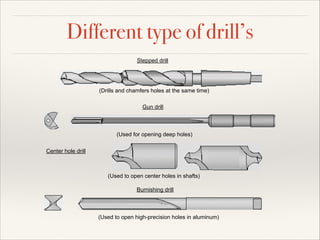
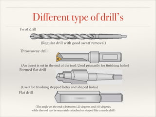
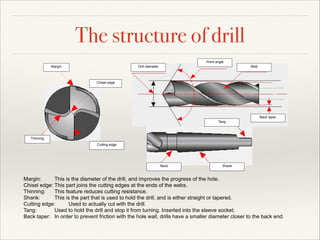
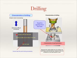
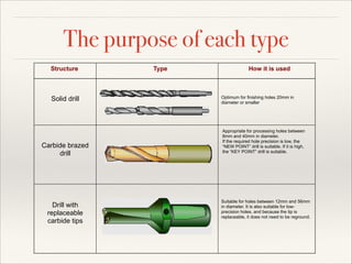
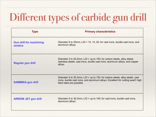
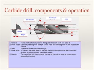
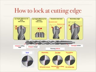
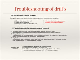
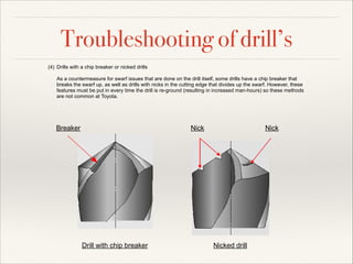


This document provides information on different types of drills, their components and how they are used. It discusses stepped drills, gun drills, center hole drills, burnishing drills, twist drills and throwaway drills. The key components of drills are identified as the point angle, margin, drill diameter, web, chisel edge, back taper, tang, thinning and cutting edge. Challenges of drilling like friction with the hole wall and difficulty seeing the point are also summarized.


![Getting Started with Apache Spark: Big Data Made Simple [Free Meetup]](https://cdn.slidesharecdn.com/ss_thumbnails/apachesparkgettingstarted-260203175547-8361bcc3-thumbnail.jpg?width=640&height=640&fit=bounds)


