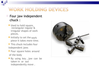
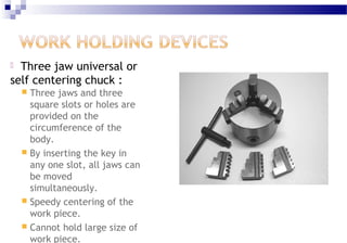
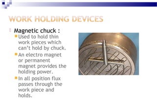
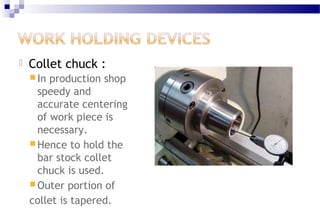
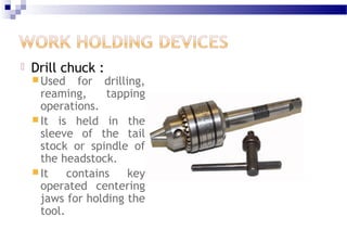
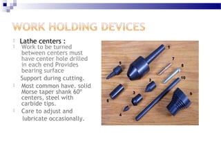
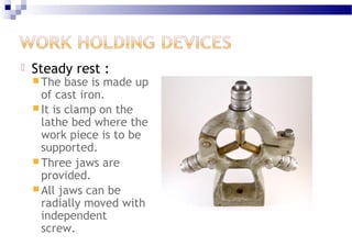
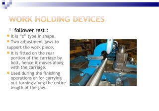
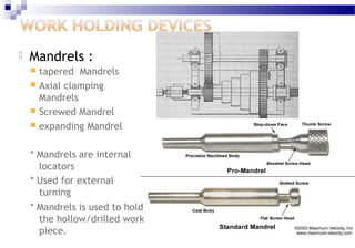
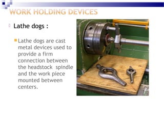
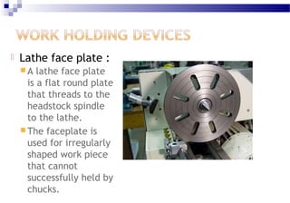
TURNING FIXTURES
 Four jaw independent
chuck :
 Used to hold square,
rectangular regular &
irregular shapes of work
pieces.
 Initially to set the work
piece it takes more time.
 This chuck includes four
independent jaws
 Four square holes around
of the body
 By using key , jaw can be
taken in or out
independently move .
 Three jaw universal or
self centering chuck :
 Three jaws and three
square slots or holes are
provided on the
circumference of the
body.
 By inserting the key in
any one slot, all jaws can
be moved
simultaneously.
 Speedy centering of the
work piece.
 Cannot hold large size of
work piece.
 Combination chuck :
 Jaws can be moved in and out simultaneously or
independently.
 Advantages of both the varieties in this chuck, so it
is called combination.
 Scroll plate is used to move the jaws simultaneously.
 A screw is used for independent movement.
 Magnetic chuck :
 Used to hold thin
work pieces which
can’t hold by chuck.
 An electro magnet
or permanent
magnet provides the
holding power.
 In all position flux
passes through the
work piece and
holds.
 Collet chuck :
 In production shop
speedy and
accurate centering
of work piece is
necessary.
 Hence to hold the
bar stock collet
chuck is used.
 Outer portion of
collet is tapered.
 Drill chuck :
 Used for drilling,
reaming, tapping
operations.
 It is held in the
sleeve of the tail
stock or spindle of
the headstock.
 It contains key
operated centering
jaws for holding the
tool.
 Lathe centers :
 Work to be turned
between centers must
have center hole drilled
in each end Provides
bearing surface
Support during cutting.
 Most common have. solid
Morse taper shank 60º
centers, steel with
carbide tips.
 Care to adjust and
lubricate occasionally.
 Steady rest :
 The base is made up
of cast iron.
 It is clamp on the
lathe bed where the
work piece is to be
supported.
 Three jaws are
provided.
 All jaws can be
radially moved with
independent
screw.
 follower rest :
 It is “c” type in shape.
 Two adjustment jaws to
support the work piece.
 It is fitted on the rear
portion of the carriage by
bolt, hence it moves along
with the carriage.
 Used during the finishing
operations or for carrying
out turning along the entire
length of the jaw.
 Mandrels :
 tapered Mandrels
 Axial clamping
Mandrels
 Screwed Mandrel
 expanding Mandrel
* Mandrels are internal
locators
* Used for external
turning
* Mandrels is used to hold
the hollow/drilled work
piece.
 Lathe dogs :
 Lathe dogs are cast
metal devices used to
provide a firm
connection between
the headstock spindle
and the work piece
mounted between
centers.
 Lathe face plate :
 A lathe face plate
is a flat round plate
that threads to the
headstock spindle
to the lathe.
 The faceplate is
used for irregularly
shaped work piece
that cannot
successfully held by
chucks.
WHY & WHEN FACE PLATE IS USED
 face plate is accurately turned and located to fit
the nose of the main spindle.
 the taper on spindle and taper on the bore of the
face plate matches exactly.
 asymmetrical work pieces can be machined
using a face plate.
 long time is required to set the work and its less
safe. this may lead to the rejection of work
piece.
 it is therefore highly advisable to go for a fixture,
if we can justify the cost.
TURNING FIXTURES
 Components produced on lathe are cheaper due
to less machine hour rate compared to costly
milling machine and costly milling cutter inserts.
 Availability of lathe is more common compared to
milling machines.
 Asymmetrical jobs can be located using a fixture
which can be drilled, turned, bored, reamed, on
lathe by using specially designed fixture.
TURNING FIXTURES
 The designed fixture can be located on a
face plate.
 The fixture must be clamped to the face
plate suitably.
 The fixture weight must be as minimum as
possible and design should take cutting
forces exerted by the tool.
SOME OF THE DESIGN CONSIDERATIONS IN TURNING
FIXTURES
 While designing the turning fixtures care should be
taken to ensure the operator’s safety .
 The accuracy of the machine tool must be protected by
placing necessary balance weights in the fixture .
 The overhang of the fixture should be minimum .
 The fixture must be properly located on the face plate .
 The fixture must be designed considering the standard
slots available in face plate for clamping the fixture.
GENERAL POINTS FOR A LATHE FIXTURE
 Reduce time required for loading and unloading
to justify reduced total cost per component, for
the quantity to be produced
 Provide adequate support for frail section or
sections under pressure from lathe tools.
 Fixture should be accurately balanced to avoid
vibrations at high spindle speeds.
 Pilot bushing for supporting tools should be
provided where extreme accuracy is required in
boring operations
GENERAL POINTS FOR A LATHE FIXTURE
 Holding the rotating work piece securely to the
fixture to resist tensional forces.
 The fixture should be rigid and overhang should
be minimum possible
 Clamping screw size should be carefully
selected to resist the cutting torque.
 Locate the work piece on critical surfaces from
where all or major and angular tolerances are
taken.
Old design for
fixture for
producing brake
drums
The new
design
Collets
EXTERNAL LOCATORS
 Collets are extensively used to locate the
cutting tools very accurately in milling /
lathe /
 Collets are made of spring steel
 The variation of the cutting tool should not
be too high ( usually the tolerance cutting
tool is h6 / h8)
TYPES OF COLLETS
 Push-out collets
 Pull-in collets
 Dead length collets
Push-out collets
Pull-in collets
Dead length collets
Cylindrical Liners
Mandrels
Mandrels
Mandrels are internal locators used for
concentric machining of outside
diameter of work pieces with finished
bores.
Types of Mandrels
 Tapered Mandrels
 Axial clamping Mandrels
 Expanding Mandrels
 Threaded Mandrels
Tapered Mandrels
 These are tapered bars with centre at the ends for
aligning with the machine axis and a flat for fixing
the drive carrier.
 Taper generally ranges from 0.4 to 0.5 mm per
meter.
 This limits the variation in the bore of the work
pieces and so, for wide difference in the bores,
different mandrels must be used.
 The taper facilitates friction drive for the work
piece, which is generally pressed on the mandrel
with an arbor press.
* For repeated use, the mandrels should be
hardened and the centers protected by
counter bores to prevent damage due to
accidental fall.
*Tapered mandrels are rarely used in mass
production as they require longer work
piece loading and unloading time.
Axial Clamping Mandrels (less
accurate for production purpose)
 These are extensively used for grinding
outside diameter of bushes.
 The locating diameter must be close push fit
with the minimum size of the work piece bore.
Consequently, the maximum bore size work
piece would be loose on the mandrel by the
amount equal to the work piece tolerance.
 Thus, the possible concentricity b/w the
inside and outside diameter of the work piece
would be equal to the tolerance on the bore of
the work piece.
 The work piece is clamped axially with a C
washer and a hexagonal nut which permit
quick loading and unloading.
 The drive pin serves as an integral drive
carrier. The mandrel is provided with
protected centers and is hardened to minimize
wear on the locating diameter.
Expanding Mandrels
 For a high degree of concentricity expanding
mandrels should be used.
 These permit adjustment of the locating
diameter to suit the variation in the bore size of
the work piece.
 In fact, expanding mandrels clamp the work
piece on the bore as collet grips the stock on
the outside diameter.
 Consequently there is no clearance between the
mandrel and the work piece which explains the
high degree of concentricity .
 The mandrel is split in to three or four pieces and
are held against the expanding cone by a retainer
spring, the clockwise rotation of the cone pushes the
mandrel pieces outwards against the work piece to
locate and clamp it.
 The rotation of the cone in the opposite direction
reduces the distance b/w the mandrel pieces which are
pressed inwards by the retainer spring.
 this contracts the mandrel to provide clearance b/w
the mandrel and work piece for easy loading and
unloading.
Threaded Mandrels
For work pieces with internal threads, the locating
mandrel should have a clamping collar which has
internal threads in the direction opposite to the
thread in the work piece. these facilitate tightening
of the work piece and the clamping collar against each
other ,and prevents the collar from unscrewing during
turning operation. for unclamping the work piece, lug
on the clamping collar is knocked in an anti-clockwise
direction by a hammer.
• The successful running of any mass
production depends upon the
interchangeability to facilitate easy assembly
and reduction of unit cost.
• Mass production methods demand a fast and
easy method of positioning work for accurate
operations on it.
• Jigs and fixtures are production tools used to
accurately manufacture duplicate and
interchangeable parts.
• Jigs and fixtures are specially designed so
that large numbers of components can be
machined or assembled identically,

Jigs & fixture turning

  • 1.
  • 4.
     Four jawindependent chuck :  Used to hold square, rectangular regular & irregular shapes of work pieces.  Initially to set the work piece it takes more time.  This chuck includes four independent jaws  Four square holes around of the body  By using key , jaw can be taken in or out independently move .
  • 5.
     Three jawuniversal or self centering chuck :  Three jaws and three square slots or holes are provided on the circumference of the body.  By inserting the key in any one slot, all jaws can be moved simultaneously.  Speedy centering of the work piece.  Cannot hold large size of work piece.
  • 6.
     Combination chuck:  Jaws can be moved in and out simultaneously or independently.  Advantages of both the varieties in this chuck, so it is called combination.  Scroll plate is used to move the jaws simultaneously.  A screw is used for independent movement.
  • 7.
     Magnetic chuck:  Used to hold thin work pieces which can’t hold by chuck.  An electro magnet or permanent magnet provides the holding power.  In all position flux passes through the work piece and holds.
  • 8.
     Collet chuck:  In production shop speedy and accurate centering of work piece is necessary.  Hence to hold the bar stock collet chuck is used.  Outer portion of collet is tapered.
  • 9.
     Drill chuck:  Used for drilling, reaming, tapping operations.  It is held in the sleeve of the tail stock or spindle of the headstock.  It contains key operated centering jaws for holding the tool.
  • 10.
     Lathe centers:  Work to be turned between centers must have center hole drilled in each end Provides bearing surface Support during cutting.  Most common have. solid Morse taper shank 60º centers, steel with carbide tips.  Care to adjust and lubricate occasionally.
  • 11.
     Steady rest:  The base is made up of cast iron.  It is clamp on the lathe bed where the work piece is to be supported.  Three jaws are provided.  All jaws can be radially moved with independent screw.
  • 12.
     follower rest:  It is “c” type in shape.  Two adjustment jaws to support the work piece.  It is fitted on the rear portion of the carriage by bolt, hence it moves along with the carriage.  Used during the finishing operations or for carrying out turning along the entire length of the jaw.
  • 13.
     Mandrels : tapered Mandrels  Axial clamping Mandrels  Screwed Mandrel  expanding Mandrel * Mandrels are internal locators * Used for external turning * Mandrels is used to hold the hollow/drilled work piece.
  • 14.
     Lathe dogs:  Lathe dogs are cast metal devices used to provide a firm connection between the headstock spindle and the work piece mounted between centers.
  • 15.
     Lathe faceplate :  A lathe face plate is a flat round plate that threads to the headstock spindle to the lathe.  The faceplate is used for irregularly shaped work piece that cannot successfully held by chucks.
  • 16.
    WHY & WHENFACE PLATE IS USED  face plate is accurately turned and located to fit the nose of the main spindle.  the taper on spindle and taper on the bore of the face plate matches exactly.  asymmetrical work pieces can be machined using a face plate.  long time is required to set the work and its less safe. this may lead to the rejection of work piece.  it is therefore highly advisable to go for a fixture, if we can justify the cost.
  • 18.
    TURNING FIXTURES  Componentsproduced on lathe are cheaper due to less machine hour rate compared to costly milling machine and costly milling cutter inserts.  Availability of lathe is more common compared to milling machines.  Asymmetrical jobs can be located using a fixture which can be drilled, turned, bored, reamed, on lathe by using specially designed fixture.
  • 19.
    TURNING FIXTURES  Thedesigned fixture can be located on a face plate.  The fixture must be clamped to the face plate suitably.  The fixture weight must be as minimum as possible and design should take cutting forces exerted by the tool.
  • 20.
    SOME OF THEDESIGN CONSIDERATIONS IN TURNING FIXTURES  While designing the turning fixtures care should be taken to ensure the operator’s safety .  The accuracy of the machine tool must be protected by placing necessary balance weights in the fixture .  The overhang of the fixture should be minimum .  The fixture must be properly located on the face plate .  The fixture must be designed considering the standard slots available in face plate for clamping the fixture.
  • 21.
    GENERAL POINTS FORA LATHE FIXTURE  Reduce time required for loading and unloading to justify reduced total cost per component, for the quantity to be produced  Provide adequate support for frail section or sections under pressure from lathe tools.  Fixture should be accurately balanced to avoid vibrations at high spindle speeds.  Pilot bushing for supporting tools should be provided where extreme accuracy is required in boring operations
  • 22.
    GENERAL POINTS FORA LATHE FIXTURE  Holding the rotating work piece securely to the fixture to resist tensional forces.  The fixture should be rigid and overhang should be minimum possible  Clamping screw size should be carefully selected to resist the cutting torque.  Locate the work piece on critical surfaces from where all or major and angular tolerances are taken.
  • 23.
    Old design for fixturefor producing brake drums The new design
  • 31.
  • 32.
    EXTERNAL LOCATORS  Colletsare extensively used to locate the cutting tools very accurately in milling / lathe /  Collets are made of spring steel  The variation of the cutting tool should not be too high ( usually the tolerance cutting tool is h6 / h8)
  • 33.
    TYPES OF COLLETS Push-out collets  Pull-in collets  Dead length collets
  • 34.
  • 35.
  • 36.
  • 37.
  • 38.
  • 39.
    Mandrels Mandrels are internallocators used for concentric machining of outside diameter of work pieces with finished bores.
  • 40.
    Types of Mandrels Tapered Mandrels  Axial clamping Mandrels  Expanding Mandrels  Threaded Mandrels
  • 41.
  • 42.
     These aretapered bars with centre at the ends for aligning with the machine axis and a flat for fixing the drive carrier.  Taper generally ranges from 0.4 to 0.5 mm per meter.  This limits the variation in the bore of the work pieces and so, for wide difference in the bores, different mandrels must be used.  The taper facilitates friction drive for the work piece, which is generally pressed on the mandrel with an arbor press.
  • 43.
    * For repeateduse, the mandrels should be hardened and the centers protected by counter bores to prevent damage due to accidental fall. *Tapered mandrels are rarely used in mass production as they require longer work piece loading and unloading time.
  • 44.
    Axial Clamping Mandrels(less accurate for production purpose)
  • 45.
     These areextensively used for grinding outside diameter of bushes.  The locating diameter must be close push fit with the minimum size of the work piece bore. Consequently, the maximum bore size work piece would be loose on the mandrel by the amount equal to the work piece tolerance.  Thus, the possible concentricity b/w the inside and outside diameter of the work piece would be equal to the tolerance on the bore of the work piece.
  • 46.
     The workpiece is clamped axially with a C washer and a hexagonal nut which permit quick loading and unloading.  The drive pin serves as an integral drive carrier. The mandrel is provided with protected centers and is hardened to minimize wear on the locating diameter.
  • 47.
  • 48.
     For ahigh degree of concentricity expanding mandrels should be used.  These permit adjustment of the locating diameter to suit the variation in the bore size of the work piece.  In fact, expanding mandrels clamp the work piece on the bore as collet grips the stock on the outside diameter.  Consequently there is no clearance between the mandrel and the work piece which explains the high degree of concentricity .
  • 49.
     The mandrelis split in to three or four pieces and are held against the expanding cone by a retainer spring, the clockwise rotation of the cone pushes the mandrel pieces outwards against the work piece to locate and clamp it.  The rotation of the cone in the opposite direction reduces the distance b/w the mandrel pieces which are pressed inwards by the retainer spring.  this contracts the mandrel to provide clearance b/w the mandrel and work piece for easy loading and unloading.
  • 50.
  • 51.
    For work pieceswith internal threads, the locating mandrel should have a clamping collar which has internal threads in the direction opposite to the thread in the work piece. these facilitate tightening of the work piece and the clamping collar against each other ,and prevents the collar from unscrewing during turning operation. for unclamping the work piece, lug on the clamping collar is knocked in an anti-clockwise direction by a hammer.
  • 52.
    • The successfulrunning of any mass production depends upon the interchangeability to facilitate easy assembly and reduction of unit cost. • Mass production methods demand a fast and easy method of positioning work for accurate operations on it. • Jigs and fixtures are production tools used to accurately manufacture duplicate and interchangeable parts. • Jigs and fixtures are specially designed so that large numbers of components can be machined or assembled identically,