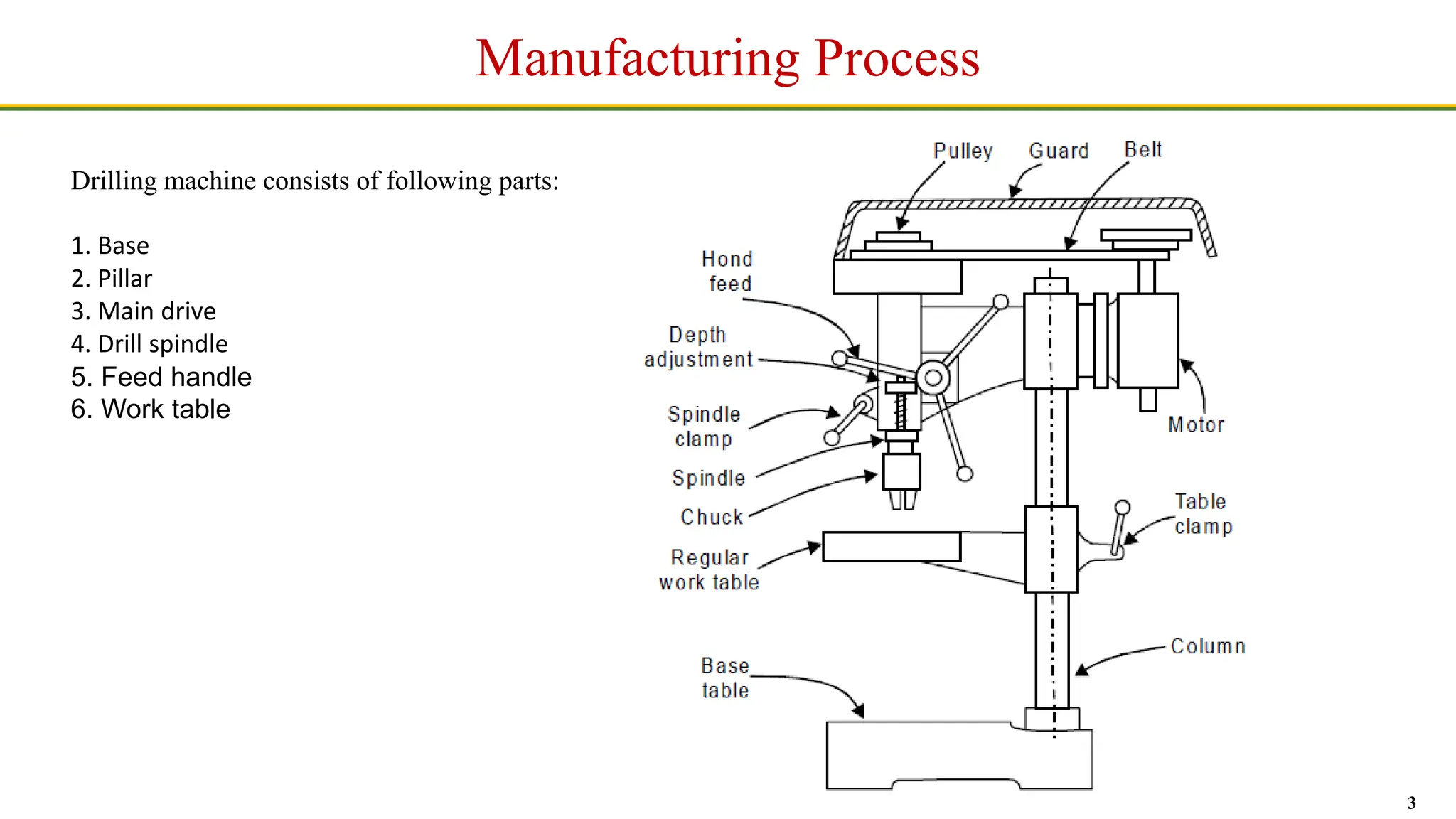
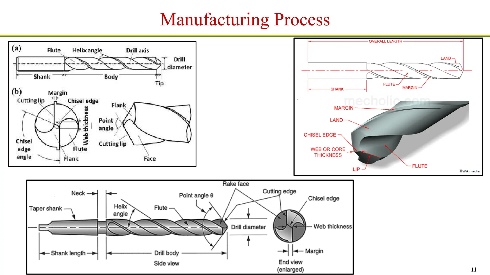
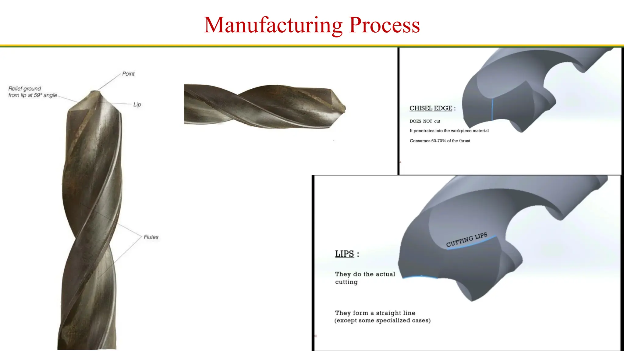
1
Manufacturing Process
Drilling
Drilling is an operation of making a circular hole by removing a volume of metal from the job by cutting tool called
drill. A drill is a rotary end-cutting tool with one or more cutting lips and usually one or more flutes for the passage
of chips and the admission of cutting fluid. A drilling machine is a machine tool designed for drilling holes in
metals. It is one of the most important and versatile machine tools in a workshop. Besides drilling round holes,
many other operations can also be performed on the drilling machine such as counter- boring, countersinking,
honing, reaming, lapping, sanding etc.
2
Manufacturing Process
CONSTRUCTION OF DRILLING MACHINE
In drilling machine the drill is rotated and fed along its axis of rotation in the stationary workpiece. Different parts of a
drilling machine are shown in Figure and are discussed below:
(i) The head containing electric motor, V-pulleys and V-belt which transmit rotary motion to the drill spindle at a number of
speeds.
(ii) Spindle is made up of alloy steel. It rotates as well as moves up and down in a sleeve. A pinion engages a rack fixed onto
the sleeve to provide vertical up and down motion of the spindle and hence the drill so that the same can be fed into the
workpiece or withdrawn from it while drilling. Spindle speed or the drill speed is changed with the help of V-belt and V-
step-pulleys. Larger drilling machines are having gear boxes for the said purpose.
(iii) Drill chuck is held at the end of the drill spindle and in turn it holds the drill bit.
(iv) Adjustable work piece table is supported on the column of the drilling machine. It can be moved both vertically and
horizontally. Tables are generally having slots so that the vice or the workpiece can be securely held on it.
(v) Base table is a heavy casting and it supports the drill press structure. The base supports the column, which in turn,
supports the table, head etc.
(vi) Column is a vertical round or box section which rests on the base and supports the head and the table. The round column
may have rack teeth cut on it so that the table can be raised or lowered depending upon the workpiece requirements. This
machine consists of following parts
3
Manufacturing Process
Drilling machine consists of following parts:
1. Base
2. Pillar
3. Main drive
4. Drill spindle
5. Feed handle
6. Work table
4
Manufacturing Process
5
Manufacturing Process
TYPES OF DRILLING MACHINE
Drilling machines are classified on the basis of their constructional features, or the type
of work they can handle. The various types of drilling machines are:
(1) Portable drilling machine
(2) Sensitive drilling machine
(a) Bench mounting
(b) Floor mounting
(3) Upright drilling machine
(a) Round column section
(b) Box column section machine
6
Manufacturing Process
(4) Radial drilling machine
(a) Plain
(b) Semi-universal
(c) Universal
(5) Gang drilling machine
(6) Multiple spindle drilling machine
(7) Automatic drilling machine
(8) Deep hole drilling machine
(a) Vertical
(b) Horizontal
7
Manufacturing Process
A drill is a multi point cutting tool used to produce or enlarge a hole in the workpiece. It usually consists of two cutting
edges set an angle with the axis. Broadly there are three types of drills:
1. Flat drill,
2. Straight-fluted drill, and
3. Twist drill
Flat drill is usually made from a piece of round steel which is forged to shape and ground to size, then hardened and
tempered. The cutting angle is usually 90 deg. and the relief or clearance at the cutting edge is 3 to 8 deg. The disadvantage
of this type of drill is that each time the drill is ground the diameter is reduced. Twist drill is the most common type of drill
in use today.
TYPES OF DRILLS
8
Manufacturing Process
Twist drill geometry and its nomenclature are shown in Figure. A twist drill has three principal parts:
(i) Drill point or dead centre.
(ii) Body.
(iii) Shank.
Twist Drill Geometry
9
Manufacturing Process
Twist Drill Geometry
Drill axis is the longitudinal centre line.
Drill point is the sharpened end of the drill body consisting of all that part which is shaped to produce lips, faces and chisel
edge.
Lip or cutting edge is the edge formed by the intersection of the flank and face
Lip length is the minimum distance between the outer corner and the chisel-edge corner of the lip.
Face is that portion of the flute surface adjacent to the lip on which the chip impinges as it is cut from the work.
Chisel edge is the edge formed by the intersection of the flanks.
Flank is that surface on a drill point which extends behind the lip to the following flute.
Flutes are the grooves in the body of the drill, which provide lips, allow the removal of chips, and permit cutting fluid to reach
the lips.
Flute length is the axial length from the extreme end of the point to the termination of the flutes at the shank end of the body.
Body is that portion of the drill nomenclature, which extends from the extreme cutting end to the beginning of the shank.
Shank is that portion of the drill by which it is held and driven, Heel is the edge formed by the intersection of the flute surface
and the body clearance.
Body clearance is that portion of the body surface reduced in diameter to provide diametric clearance.
10
Manufacturing Process
Core or web is the central portion of the drill situated between the roots of the flutes and extending from the point end
towards the shank; the point end of the core forms the chisel edge.
Lands are the cylindrically ground surfaces on the leading edges of the drill flutes. The width of the land is measured at right
angles to the flute.
Recess is the portion of the drill body between the flutes and the shank provided so as to facilitate the grinding of the body.
Parallel shank drills of small diameter are not usually provided with a recess. Outer corner is the corner formed by the
intersection of the lip and the leading edge of the land.
Chisel edge comer is the corner formed by the intersection of a lip and the chisel edge. Drill diameter is the measurement
across the cylindrical lands at the outer corners of the drill. .
Lead of helix is the distance measured parallel to the drill axis between corresponding points on the leading edge of a flute in
one complete turn of the flute.
Helix angle is the angle between the leading edge of the land and the drill axis.
Rake angle is the angle between the face and a line parallel to the drill axis. It is bigger
at the face edges and decreases towards the centre of the drill to nearly 0°. The result is that the formation of chips grows more
unfavourable towards the centre.
Lip clearance angle is the angle formed by the flank and a plane at right angles to the drill axis; the angle is normally measured
at the periphery of the drill. To make sure that the main cutting edges can enter into the material, the clearance faces slope
backwards in a curve. The clearance angle is measured at the face edge, must amount to 5° up to 8°.
Point angle is the included angle of the cone formed by the lips.
11
Manufacturing Process
12
Manufacturing Process
13
Manufacturing Process
Twist Drill Geometry
14
Manufacturing Process
15
Manufacturing Process
16
Manufacturing Process
17
Manufacturing Process
Land
18
Manufacturing Process
19
Manufacturing Process
20
Manufacturing Process
21
Manufacturing Process
22
Manufacturing Process
23
Manufacturing Process

Different types of Drilling Machine in simple terms

  • 1.
    1 Manufacturing Process Drilling Drilling isan operation of making a circular hole by removing a volume of metal from the job by cutting tool called drill. A drill is a rotary end-cutting tool with one or more cutting lips and usually one or more flutes for the passage of chips and the admission of cutting fluid. A drilling machine is a machine tool designed for drilling holes in metals. It is one of the most important and versatile machine tools in a workshop. Besides drilling round holes, many other operations can also be performed on the drilling machine such as counter- boring, countersinking, honing, reaming, lapping, sanding etc.
  • 2.
    2 Manufacturing Process CONSTRUCTION OFDRILLING MACHINE In drilling machine the drill is rotated and fed along its axis of rotation in the stationary workpiece. Different parts of a drilling machine are shown in Figure and are discussed below: (i) The head containing electric motor, V-pulleys and V-belt which transmit rotary motion to the drill spindle at a number of speeds. (ii) Spindle is made up of alloy steel. It rotates as well as moves up and down in a sleeve. A pinion engages a rack fixed onto the sleeve to provide vertical up and down motion of the spindle and hence the drill so that the same can be fed into the workpiece or withdrawn from it while drilling. Spindle speed or the drill speed is changed with the help of V-belt and V- step-pulleys. Larger drilling machines are having gear boxes for the said purpose. (iii) Drill chuck is held at the end of the drill spindle and in turn it holds the drill bit. (iv) Adjustable work piece table is supported on the column of the drilling machine. It can be moved both vertically and horizontally. Tables are generally having slots so that the vice or the workpiece can be securely held on it. (v) Base table is a heavy casting and it supports the drill press structure. The base supports the column, which in turn, supports the table, head etc. (vi) Column is a vertical round or box section which rests on the base and supports the head and the table. The round column may have rack teeth cut on it so that the table can be raised or lowered depending upon the workpiece requirements. This machine consists of following parts
  • 3.
    3 Manufacturing Process Drilling machineconsists of following parts: 1. Base 2. Pillar 3. Main drive 4. Drill spindle 5. Feed handle 6. Work table
  • 4.
  • 5.
    5 Manufacturing Process TYPES OFDRILLING MACHINE Drilling machines are classified on the basis of their constructional features, or the type of work they can handle. The various types of drilling machines are: (1) Portable drilling machine (2) Sensitive drilling machine (a) Bench mounting (b) Floor mounting (3) Upright drilling machine (a) Round column section (b) Box column section machine
  • 6.
    6 Manufacturing Process (4) Radialdrilling machine (a) Plain (b) Semi-universal (c) Universal (5) Gang drilling machine (6) Multiple spindle drilling machine (7) Automatic drilling machine (8) Deep hole drilling machine (a) Vertical (b) Horizontal
  • 7.
    7 Manufacturing Process A drillis a multi point cutting tool used to produce or enlarge a hole in the workpiece. It usually consists of two cutting edges set an angle with the axis. Broadly there are three types of drills: 1. Flat drill, 2. Straight-fluted drill, and 3. Twist drill Flat drill is usually made from a piece of round steel which is forged to shape and ground to size, then hardened and tempered. The cutting angle is usually 90 deg. and the relief or clearance at the cutting edge is 3 to 8 deg. The disadvantage of this type of drill is that each time the drill is ground the diameter is reduced. Twist drill is the most common type of drill in use today. TYPES OF DRILLS
  • 8.
    8 Manufacturing Process Twist drillgeometry and its nomenclature are shown in Figure. A twist drill has three principal parts: (i) Drill point or dead centre. (ii) Body. (iii) Shank. Twist Drill Geometry
  • 9.
    9 Manufacturing Process Twist DrillGeometry Drill axis is the longitudinal centre line. Drill point is the sharpened end of the drill body consisting of all that part which is shaped to produce lips, faces and chisel edge. Lip or cutting edge is the edge formed by the intersection of the flank and face Lip length is the minimum distance between the outer corner and the chisel-edge corner of the lip. Face is that portion of the flute surface adjacent to the lip on which the chip impinges as it is cut from the work. Chisel edge is the edge formed by the intersection of the flanks. Flank is that surface on a drill point which extends behind the lip to the following flute. Flutes are the grooves in the body of the drill, which provide lips, allow the removal of chips, and permit cutting fluid to reach the lips. Flute length is the axial length from the extreme end of the point to the termination of the flutes at the shank end of the body. Body is that portion of the drill nomenclature, which extends from the extreme cutting end to the beginning of the shank. Shank is that portion of the drill by which it is held and driven, Heel is the edge formed by the intersection of the flute surface and the body clearance. Body clearance is that portion of the body surface reduced in diameter to provide diametric clearance.
  • 10.
    10 Manufacturing Process Core orweb is the central portion of the drill situated between the roots of the flutes and extending from the point end towards the shank; the point end of the core forms the chisel edge. Lands are the cylindrically ground surfaces on the leading edges of the drill flutes. The width of the land is measured at right angles to the flute. Recess is the portion of the drill body between the flutes and the shank provided so as to facilitate the grinding of the body. Parallel shank drills of small diameter are not usually provided with a recess. Outer corner is the corner formed by the intersection of the lip and the leading edge of the land. Chisel edge comer is the corner formed by the intersection of a lip and the chisel edge. Drill diameter is the measurement across the cylindrical lands at the outer corners of the drill. . Lead of helix is the distance measured parallel to the drill axis between corresponding points on the leading edge of a flute in one complete turn of the flute. Helix angle is the angle between the leading edge of the land and the drill axis. Rake angle is the angle between the face and a line parallel to the drill axis. It is bigger at the face edges and decreases towards the centre of the drill to nearly 0°. The result is that the formation of chips grows more unfavourable towards the centre. Lip clearance angle is the angle formed by the flank and a plane at right angles to the drill axis; the angle is normally measured at the periphery of the drill. To make sure that the main cutting edges can enter into the material, the clearance faces slope backwards in a curve. The clearance angle is measured at the face edge, must amount to 5° up to 8°. Point angle is the included angle of the cone formed by the lips.
  • 11.
  • 12.
  • 13.
  • 14.
  • 15.
  • 16.
  • 17.
  • 18.
  • 19.
  • 20.
  • 21.
  • 22.
  • 23.