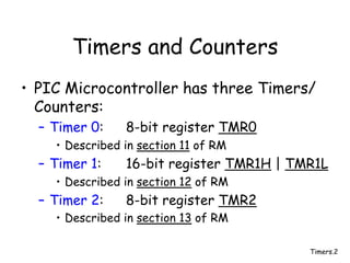
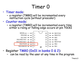
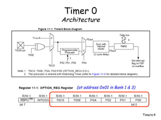
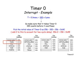
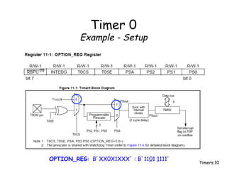
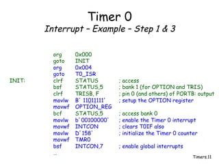
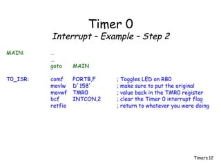
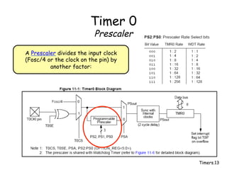
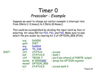
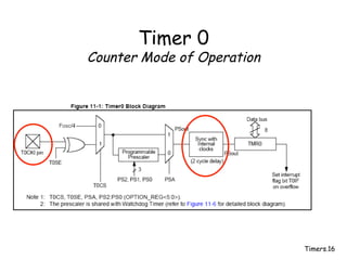
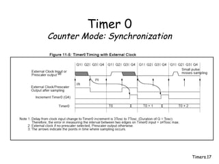
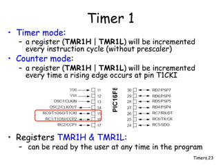
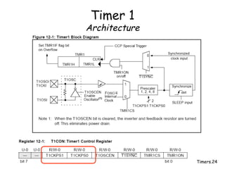
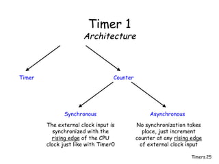
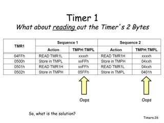
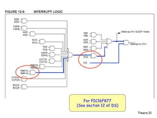
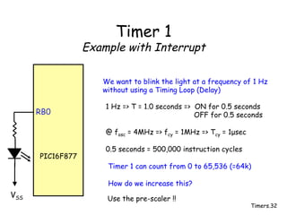
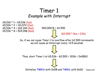
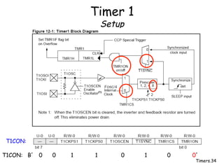
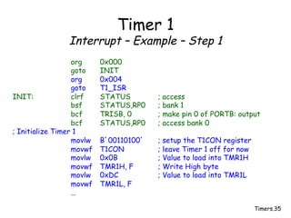
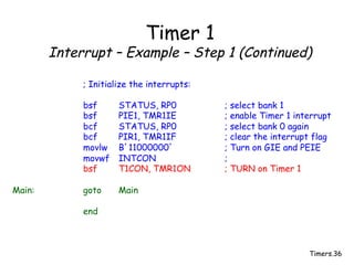
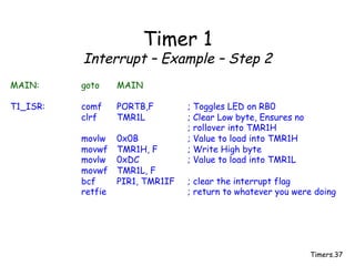
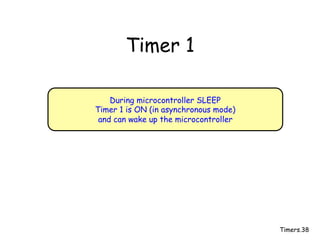
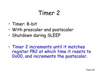
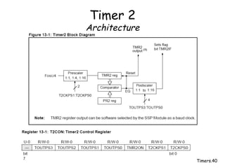
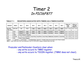
Timers.1
Microprocessors and Microcontrollers
Timers & Counters
Timers.2
Timers and Counters
• PIC Microcontroller has three Timers/
Counters:
– Timer 0: 8-bit register TMR0
• Described in section 11 of RM
– Timer 1: 16-bit register TMR1H | TMR1L
• Described in section 12 of RM
– Timer 2: 8-bit register TMR2
• Described in section 13 of RM
Timers.3
Timer 0
• Timer mode:
– a register (TMR0) will be incremented every
instruction cycle (without prescaler)
• Counter mode:
– a register (TMR0) will be incremented every time
either a rising or falling edge occurs at pin T0CKI
• Register TMR0 (0x01 in banks 0 & 2):
– can be read by the user at any time in the program
Timers.4
Timer 0
Architecture
(at address 0x01 in Bank 1 & 3)
Timers.5
Timer 0
Writing to TMR0 ( 0x01 banks 0 & 2)
A write to TMR0 will cause
a 2 instruction cycle (2TCY) inhibit !!!!!
Timers.6
Timer 0
Interrupt
A TIMER 0 interrupt is generated when the TIMER 0 overflows from
0xFF to 0x00
In INTCON bit 5 (NOTE: Timer 0 is turned off during SLEEP)
Timers.7
Timer 0
Interrupt
bit 2
bit 5
bit 7
See Reference Manual pp.171
( at location 0x0B in all banks )
Timers.8
Timer 0
Interrupt - Example
PIC16F877
VSS
RB0
Blink InfraRed (IR) LED at a rate of 5kHz
5kHz => T = 0.2msec => ON for 0.1 ms
OFF for 0.1 ms
If run at maximum speed and selecting
the microcontroller’s oscillator as the timer’s input,
the counter/timer gets incremented every 1µsec.
IR
fosc = 4MHz
T = 0.1msec = 100 x 1µsec
Timers.9
Timer 0
Interrupt - Example
T = 0.1msec = 100 x 1µsec
So make sure that it takes Timer 0
100 counts before it overflows:
Pick the initial value of Timer 0 as 256 – 100 = 156 = 0x9C
( add 2 to this to account for two-cycle delay) 156+2 = 158 = 0x9E
Timers.10
Timer 0
Example - Setup
OPTION_REG: B’XX0X1XXX’ : B’1101 1111’
Timers.11
Timer 0
Interrupt – Example – Step 1 & 3
org 0x000
goto INIT
org 0x004
goto T0_ISR
INIT: clrf STATUS ; access
bsf STATUS,5 ; bank 1 (for OPTION and TRIS)
clrf TRISB, F ; pin 0 (and others) of PORTB: output
movlw B’ 11011111’ ; setup the OPTION register
movwf OPTION_REG
bcf STATUS,5 ; access bank 0
movlw b’00100000’ ; enable the Timer 0 interrupt
movwf INTCON ; clears T0IF also
movlw D’158’ ; initialize the Timer 0 counter
movwf TMR0
bsf INTCON,7 ; enable global interrupts
…
Timers.12
Timer 0
Interrupt – Example – Step 2
MAIN: …
…
goto MAIN
T0_ISR: comf PORTB,F ; Toggles LED on RB0
movlw D’158’ ; make sure to put the original
movwf TMR0 ; value back in the TMR0 register
bcf INTCON,2 ; clear the Timer 0 interrupt flag
retfie ; return to whatever you were doing
Timers.13
Timer 0
Prescaler
A Prescaler divides the input clock
(Fosc/4 or the clock on the pin) by
another factor:
Timers.14
Timer 0
Prescaler - Example
Suppose we want to change our earlier example’s interrupt rate
from 10kHz (= 0.1msec) to 2.5kHz (0.4msec).
This could be accomplished by dividing the input clock by four or
selecting bit value 001 for PS2, PS1, and PS0. Make sure to also
select the pre-scalar by clearing bit 3 of OPTION_REG (PSA).
org 0x0000
goto INIT
org 0x0004
goto T0_ISR
INIT: clrf STATUS ; access
bsf STATUS,5 ; bank 1
clrf TRISB, F ; pin 0 (an others) of PORTB: output
movlw B’00000001’ ; setup the OPTION register
movwf OPTION_REG
bcf STATUS,5 ; access bank 0
…
Timers.15
Timer 0
Prescaler
• The Prescaler is shared with the
WatchDog timer … but more about
that one later.
Timers.16
Timer 0
Counter Mode of Operation
Timers.17
Timer 0
Counter Mode: Synchronization
Timers.18
Timer 0
Counter Mode of Operation
PIC16F877
T0CKI
External
Clock
or
T0SE = 0:
T0SE = 1:
OPTION_REG
CPU
Clock
OSC1
Timers.19
Timer 0
Counter Mode Example
Count the number of times someone pushes a button given the
following hardware setup.
PIC16F877
Vss
VDD
T0CKI
If button is pushed the
voltage on the T0CKI pin
goes from VDD to VSS.
In other words we want
to detect a falling edge:
T0SE = 1
Timers.20
Timer 0
Counter Mode Example
OPTION_REG: B’XX111XXX’ : B’11111111’
Timers.21
Timer 0
Counter Mode Example
org 0x000
INIT: clrf TMR0,F ; clear the counter (2TCY inhibit)
clrf STATUS ; access
bsf STATUS,RP0 ; bank 1
movlw B’ 11111111’ ; setup the OPTION register
movwf OPTION_REG
bcf STATUS,RP0 ; access bank 0
MAIN: …
…
…
movf TMR0,W ; read the number of button pushes
…
…
…
Timers.22
Timer 0
During microcontroller SLEEP
Timer 0 is shutdown
Timers.23
Timer 1
• Timer mode:
– a register (TMR1H | TMR1L) will be incremented
every instruction cycle (without prescaler)
• Counter mode:
– a register (TMR1H | TMR1L) will be incremented
every time a rising edge occurs at pin T1CKI
• Registers TMR1H & TMR1L:
– can be read by the user at any time in the program
Timers.24
Timer 1
Architecture
Timers.25
Timer 1
Architecture
Timer Counter
Synchronous Asynchronous
The external clock input is
synchronized with the
rising edge of the CPU
clock just like with Timer0
No synchronization takes
place, just increment
counter at any rising edge
of external clock input
Timers.26
Timer 1
What about reading out the Timer’s 2 Bytes
Oops Oops
So, what is the solution?
Timers.27
Timer 1
What about reading out the Timer’s 2 Bytes
; All interrupts are disabled
movf TMR1H, W ; Read high byte
movwf TMPH ;
movf TMR1L, W ; Read low byte
movwf TMPL ;
movf TMR1H, W ; Read high byte
subwf TMPH, W ; Sub 1st read with 2nd read
btfsc STATUS,Z ; Is result = 0
goto CONTINUE ; Good 16-bit read
;
; TMR1L may have rolled over between the read of the high and low bytes.
; Reading the high and low bytes now will read a good value.
;
movf TMR1H, W ; Read high byte
movwf TMPH ;
movf TMR1L, W ; Read low byte
movwf TMPL ;
; Re-enable the Interrupt (if required)
CONTINUE … ; Continue with your code
Timers.28
Timer 1
What about writing out the Timer’s 2 Bytes
; All interrupts are disabled
clrf TMR1L ; Clear Low byte, Ensures no
; rollover into TMR1H
movlw HI_BYTE ; Value to load into TMR1H
movwf TMR1H, F ; Write High byte
movlw LO_BYTE ; Value to load into TMR1L
movwf TMR1L, F ; Write Low byte
; Re-enable the Interrupt (if required)
CONTINUE … ; Continue with your code
Timers.29
Timer 1
Associated Registers
To turn the Timer 1 On
Timers.30
Timer 1
Associated Registers (Interrupts)
Flag & Enable bits
Peripheral Interrupt Enable
Timers.31
For PIC16F877
(See section 12 of DS)
Timers.32
Timer 1
Example with Interrupt
PIC16F877
VSS
RB0
We want to blink the light at a frequency of 1 Hz
without using a Timing Loop (Delay)
1 Hz => T = 1.0 seconds => ON for 0.5 seconds
OFF for 0.5 seconds
@ fosc = 4MHz => fcy = 1MHz => Tcy = 1µsec
0.5 seconds = 500,000 instruction cycles
Timer 1 can count from 0 to 65,536 (=64k)
How do we increase this?
Use the pre-scaler !!
Timers.33
Timer 1
Example with Interrupt
65,536 * 1 = 65,536 (1us)
65,536 * 2 = 131,072 (2us)
65,536 * 4 = 262,144 (4us)
65,536 * 8 = 524,288 (8us)
500,000/8 = 62,500
So, if we can cause Timer 1 to overflow after 62,500 increments
we will cause an Interrupt every ~0.5 seconds
Thus, start Timer 1 at 65,536 – 62,500 = 3036 = 0x0BDC
Initialize TMR1H with 0x0B and TMR1L with 0xDC
(62,500 * 8us = 0.5s)
Timers.34
Timer 1
Setup
T1CON:
T1CON: B’ 0 0 1 1 0 1 0 0’
Timers.35
Timer 1
Interrupt – Example – Step 1
org 0x000
goto INIT
org 0x004
goto T1_ISR
INIT: clrf STATUS ; access
bsf STATUS,RP0 ; bank 1
bcf TRISB, 0 ; make pin 0 of PORTB: output
bcf STATUS,RP0 ; access bank 0
; Initialize Timer 1
movlw B’00110100’ ; setup the T1CON register
movwf T1CON ; leave Timer 1 off for now
movlw 0x0B ; Value to load into TMR1H
movwf TMR1H, F ; Write High byte
movlw 0xDC ; Value to load into TMR1L
movwf TMR1L, F
…
Timers.36
Timer 1
Interrupt – Example – Step 1 (Continued)
; Initialize the interrupts:
bsf STATUS, RP0 ; select bank 1
bsf PIE1, TMR1IE ; enable Timer 1 interrupt
bcf STATUS, RP0 ; select bank 0 again
bcf PIR1, TMR1IF ; clear the interrupt flag
movlw B’11000000’ ; Turn on GIE and PEIE
movwf INTCON ;
bsf T1CON, TMR1ON ; TURN on Timer 1
Main: goto Main
end
Timers.37
Timer 1
Interrupt – Example – Step 2
MAIN: goto MAIN
T1_ISR: comf PORTB,F ; Toggles LED on RB0
clrf TMR1L ; Clear Low byte, Ensures no
; rollover into TMR1H
movlw 0x0B ; Value to load into TMR1H
movwf TMR1H, F ; Write High byte
movlw 0xDC ; Value to load into TMR1L
movwf TMR1L, F
bcf PIR1, TMR1IF ; clear the interrupt flag
retfie ; return to whatever you were doing
Timers.38
Timer 1
During microcontroller SLEEP
Timer 1 is ON (in asynchronous mode)
and can wake up the microcontroller
Timers.39
Timer 2
• Timer: 8-bit
• With prescaler and postscaler
• Shutdown during SLEEP
• Timer 2 increments until it matches
register PR2 at which time it resets to
0x00, and increments the postscalar.
Timers.40
Timer 2
Architecture
Timers.41
Timer 2
In PIC16F877
Prescaler and Postscaler Counters clear when:
- any write occurs to TMR2 register.
- any write occurs to T2CON register. (TMR2 does not clear).

timers.pdf

  • 1.
  • 2.
    Timers.2 Timers and Counters •PIC Microcontroller has three Timers/ Counters: – Timer 0: 8-bit register TMR0 • Described in section 11 of RM – Timer 1: 16-bit register TMR1H | TMR1L • Described in section 12 of RM – Timer 2: 8-bit register TMR2 • Described in section 13 of RM
  • 3.
    Timers.3 Timer 0 • Timermode: – a register (TMR0) will be incremented every instruction cycle (without prescaler) • Counter mode: – a register (TMR0) will be incremented every time either a rising or falling edge occurs at pin T0CKI • Register TMR0 (0x01 in banks 0 & 2): – can be read by the user at any time in the program
  • 4.
  • 5.
    Timers.5 Timer 0 Writing toTMR0 ( 0x01 banks 0 & 2) A write to TMR0 will cause a 2 instruction cycle (2TCY) inhibit !!!!!
  • 6.
    Timers.6 Timer 0 Interrupt A TIMER0 interrupt is generated when the TIMER 0 overflows from 0xFF to 0x00 In INTCON bit 5 (NOTE: Timer 0 is turned off during SLEEP)
  • 7.
    Timers.7 Timer 0 Interrupt bit 2 bit5 bit 7 See Reference Manual pp.171 ( at location 0x0B in all banks )
  • 8.
    Timers.8 Timer 0 Interrupt -Example PIC16F877 VSS RB0 Blink InfraRed (IR) LED at a rate of 5kHz 5kHz => T = 0.2msec => ON for 0.1 ms OFF for 0.1 ms If run at maximum speed and selecting the microcontroller’s oscillator as the timer’s input, the counter/timer gets incremented every 1µsec. IR fosc = 4MHz T = 0.1msec = 100 x 1µsec
  • 9.
    Timers.9 Timer 0 Interrupt -Example T = 0.1msec = 100 x 1µsec So make sure that it takes Timer 0 100 counts before it overflows: Pick the initial value of Timer 0 as 256 – 100 = 156 = 0x9C ( add 2 to this to account for two-cycle delay) 156+2 = 158 = 0x9E
  • 10.
    Timers.10 Timer 0 Example -Setup OPTION_REG: B’XX0X1XXX’ : B’1101 1111’
  • 11.
    Timers.11 Timer 0 Interrupt –Example – Step 1 & 3 org 0x000 goto INIT org 0x004 goto T0_ISR INIT: clrf STATUS ; access bsf STATUS,5 ; bank 1 (for OPTION and TRIS) clrf TRISB, F ; pin 0 (and others) of PORTB: output movlw B’ 11011111’ ; setup the OPTION register movwf OPTION_REG bcf STATUS,5 ; access bank 0 movlw b’00100000’ ; enable the Timer 0 interrupt movwf INTCON ; clears T0IF also movlw D’158’ ; initialize the Timer 0 counter movwf TMR0 bsf INTCON,7 ; enable global interrupts …
  • 12.
    Timers.12 Timer 0 Interrupt –Example – Step 2 MAIN: … … goto MAIN T0_ISR: comf PORTB,F ; Toggles LED on RB0 movlw D’158’ ; make sure to put the original movwf TMR0 ; value back in the TMR0 register bcf INTCON,2 ; clear the Timer 0 interrupt flag retfie ; return to whatever you were doing
  • 13.
    Timers.13 Timer 0 Prescaler A Prescalerdivides the input clock (Fosc/4 or the clock on the pin) by another factor:
  • 14.
    Timers.14 Timer 0 Prescaler -Example Suppose we want to change our earlier example’s interrupt rate from 10kHz (= 0.1msec) to 2.5kHz (0.4msec). This could be accomplished by dividing the input clock by four or selecting bit value 001 for PS2, PS1, and PS0. Make sure to also select the pre-scalar by clearing bit 3 of OPTION_REG (PSA). org 0x0000 goto INIT org 0x0004 goto T0_ISR INIT: clrf STATUS ; access bsf STATUS,5 ; bank 1 clrf TRISB, F ; pin 0 (an others) of PORTB: output movlw B’00000001’ ; setup the OPTION register movwf OPTION_REG bcf STATUS,5 ; access bank 0 …
  • 15.
    Timers.15 Timer 0 Prescaler • ThePrescaler is shared with the WatchDog timer … but more about that one later.
  • 16.
  • 17.
  • 18.
    Timers.18 Timer 0 Counter Modeof Operation PIC16F877 T0CKI External Clock or T0SE = 0: T0SE = 1: OPTION_REG CPU Clock OSC1
  • 19.
    Timers.19 Timer 0 Counter ModeExample Count the number of times someone pushes a button given the following hardware setup. PIC16F877 Vss VDD T0CKI If button is pushed the voltage on the T0CKI pin goes from VDD to VSS. In other words we want to detect a falling edge: T0SE = 1
  • 20.
    Timers.20 Timer 0 Counter ModeExample OPTION_REG: B’XX111XXX’ : B’11111111’
  • 21.
    Timers.21 Timer 0 Counter ModeExample org 0x000 INIT: clrf TMR0,F ; clear the counter (2TCY inhibit) clrf STATUS ; access bsf STATUS,RP0 ; bank 1 movlw B’ 11111111’ ; setup the OPTION register movwf OPTION_REG bcf STATUS,RP0 ; access bank 0 MAIN: … … … movf TMR0,W ; read the number of button pushes … … …
  • 22.
  • 23.
    Timers.23 Timer 1 • Timermode: – a register (TMR1H | TMR1L) will be incremented every instruction cycle (without prescaler) • Counter mode: – a register (TMR1H | TMR1L) will be incremented every time a rising edge occurs at pin T1CKI • Registers TMR1H & TMR1L: – can be read by the user at any time in the program
  • 24.
  • 25.
    Timers.25 Timer 1 Architecture Timer Counter SynchronousAsynchronous The external clock input is synchronized with the rising edge of the CPU clock just like with Timer0 No synchronization takes place, just increment counter at any rising edge of external clock input
  • 26.
    Timers.26 Timer 1 What aboutreading out the Timer’s 2 Bytes Oops Oops So, what is the solution?
  • 27.
    Timers.27 Timer 1 What aboutreading out the Timer’s 2 Bytes ; All interrupts are disabled movf TMR1H, W ; Read high byte movwf TMPH ; movf TMR1L, W ; Read low byte movwf TMPL ; movf TMR1H, W ; Read high byte subwf TMPH, W ; Sub 1st read with 2nd read btfsc STATUS,Z ; Is result = 0 goto CONTINUE ; Good 16-bit read ; ; TMR1L may have rolled over between the read of the high and low bytes. ; Reading the high and low bytes now will read a good value. ; movf TMR1H, W ; Read high byte movwf TMPH ; movf TMR1L, W ; Read low byte movwf TMPL ; ; Re-enable the Interrupt (if required) CONTINUE … ; Continue with your code
  • 28.
    Timers.28 Timer 1 What aboutwriting out the Timer’s 2 Bytes ; All interrupts are disabled clrf TMR1L ; Clear Low byte, Ensures no ; rollover into TMR1H movlw HI_BYTE ; Value to load into TMR1H movwf TMR1H, F ; Write High byte movlw LO_BYTE ; Value to load into TMR1L movwf TMR1L, F ; Write Low byte ; Re-enable the Interrupt (if required) CONTINUE … ; Continue with your code
  • 29.
  • 30.
    Timers.30 Timer 1 Associated Registers(Interrupts) Flag & Enable bits Peripheral Interrupt Enable
  • 31.
  • 32.
    Timers.32 Timer 1 Example withInterrupt PIC16F877 VSS RB0 We want to blink the light at a frequency of 1 Hz without using a Timing Loop (Delay) 1 Hz => T = 1.0 seconds => ON for 0.5 seconds OFF for 0.5 seconds @ fosc = 4MHz => fcy = 1MHz => Tcy = 1µsec 0.5 seconds = 500,000 instruction cycles Timer 1 can count from 0 to 65,536 (=64k) How do we increase this? Use the pre-scaler !!
  • 33.
    Timers.33 Timer 1 Example withInterrupt 65,536 * 1 = 65,536 (1us) 65,536 * 2 = 131,072 (2us) 65,536 * 4 = 262,144 (4us) 65,536 * 8 = 524,288 (8us) 500,000/8 = 62,500 So, if we can cause Timer 1 to overflow after 62,500 increments we will cause an Interrupt every ~0.5 seconds Thus, start Timer 1 at 65,536 – 62,500 = 3036 = 0x0BDC Initialize TMR1H with 0x0B and TMR1L with 0xDC (62,500 * 8us = 0.5s)
  • 34.
  • 35.
    Timers.35 Timer 1 Interrupt –Example – Step 1 org 0x000 goto INIT org 0x004 goto T1_ISR INIT: clrf STATUS ; access bsf STATUS,RP0 ; bank 1 bcf TRISB, 0 ; make pin 0 of PORTB: output bcf STATUS,RP0 ; access bank 0 ; Initialize Timer 1 movlw B’00110100’ ; setup the T1CON register movwf T1CON ; leave Timer 1 off for now movlw 0x0B ; Value to load into TMR1H movwf TMR1H, F ; Write High byte movlw 0xDC ; Value to load into TMR1L movwf TMR1L, F …
  • 36.
    Timers.36 Timer 1 Interrupt –Example – Step 1 (Continued) ; Initialize the interrupts: bsf STATUS, RP0 ; select bank 1 bsf PIE1, TMR1IE ; enable Timer 1 interrupt bcf STATUS, RP0 ; select bank 0 again bcf PIR1, TMR1IF ; clear the interrupt flag movlw B’11000000’ ; Turn on GIE and PEIE movwf INTCON ; bsf T1CON, TMR1ON ; TURN on Timer 1 Main: goto Main end
  • 37.
    Timers.37 Timer 1 Interrupt –Example – Step 2 MAIN: goto MAIN T1_ISR: comf PORTB,F ; Toggles LED on RB0 clrf TMR1L ; Clear Low byte, Ensures no ; rollover into TMR1H movlw 0x0B ; Value to load into TMR1H movwf TMR1H, F ; Write High byte movlw 0xDC ; Value to load into TMR1L movwf TMR1L, F bcf PIR1, TMR1IF ; clear the interrupt flag retfie ; return to whatever you were doing
  • 38.
    Timers.38 Timer 1 During microcontrollerSLEEP Timer 1 is ON (in asynchronous mode) and can wake up the microcontroller
  • 39.
    Timers.39 Timer 2 • Timer:8-bit • With prescaler and postscaler • Shutdown during SLEEP • Timer 2 increments until it matches register PR2 at which time it resets to 0x00, and increments the postscalar.
  • 40.
  • 41.
    Timers.41 Timer 2 In PIC16F877 Prescalerand Postscaler Counters clear when: - any write occurs to TMR2 register. - any write occurs to T2CON register. (TMR2 does not clear).