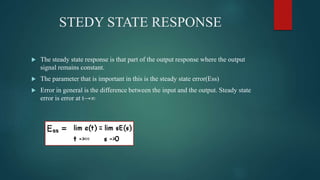
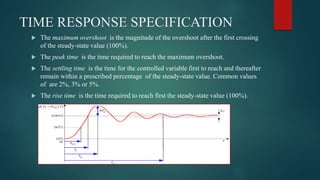
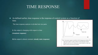
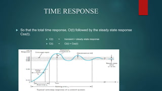
This document provides an overview of time response analysis for control systems. It discusses how a system's output changes over time in response to different input functions, including impulse, step, ramp, parabolic, and sinusoidal inputs. The time response has two parts: the transient response, where the output is changing, and the steady state response, where the output is constant. Specifications for time response include maximum overshoot, peak time, settling time, and rise time. Both time and frequency domain analyses are used to evaluate control systems, with frequency domain being simpler for higher order systems.


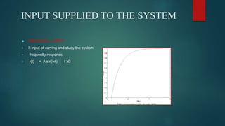
![INPUT SUPPLIED TO THE SYSTEM
IMPULSE INPUT
• It is sudden change input. An impulse is infinite
• at t=0 and everywhere else.
• r(t)= δ(t)= 1 t =0
= 0 t ≠o
In lmpulse domain we have,
• L[r(t)]= 1
STEP INPUT
• It represents a constant command such
• as position. Like elevator is a step input.
• r(t)= u(t)= A t ≥0
= 0 otherwise
L[r(t)]= A/s](https://image.slidesharecdn.com/timeresponseandanalysiskaushalshah-171122163244/85/Time-response-and-analysis-kaushal-shah-8-320.jpg)
![INPUT SUPPLIED TO THE SYSTEM
RAMP INPUT
• this represents a linearly
• increasing input command.
• r(t) = At t ≥0,Aslope
= 0 t <0
L[r(t)]= A/s²
A= 1 then unit ramp
PARABOLIC INPUT
• Rate of change of velocity is
• acceleration. Acceleration is a parabolic
• function.
• r(t) = At ²/2 t ≥0
= 0 t <0
L[r(t)]= A/s³](https://image.slidesharecdn.com/timeresponseandanalysiskaushalshah-171122163244/85/Time-response-and-analysis-kaushal-shah-9-320.jpg)