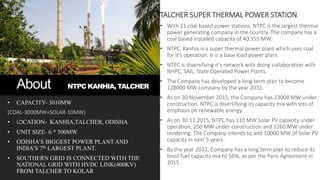
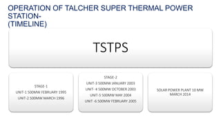
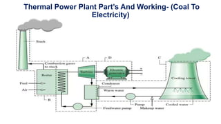
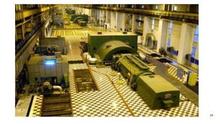
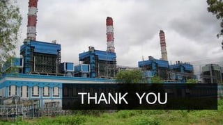
INDUSTRIAL
TRAINING
AT- NTPC, KANHIA,TALCHER
About NTPC KANHIA, TALCHER
• CAPACITY- 3010MW
(COAL-3000MW+SOLAR-10MW)
• LOCATION- KANHIA,TALCHER, ODISHA
• UNIT SIZE- 6 * 500MW
• ODISHA’S BIGGEST POWER PLANT AND
INDIA’S 7th LARGEST PLANT.
• SOUTHERN GRID IS CONNECTED WITH THE
NATIONAL GRID WITH HVDC LINK(400KV)
FROM TALCHER TO KOLAR
TALCHER SUPER THERMAL POWER STATION
• With 21 coal based power stations, NTPC is the largest thermal
power generating company in the country. The company has a
coal based installed capacity of 40,355 MW.
• NTPC, Kanhia is a super thermal power plant which uses coal
for it’s operation. It is a base load power plant.
• NTPC is diversifying it’s network with doing collaboration with
NHPC, SAIL, State Operated Power Plants.
• The Company has developed a long term plan to become
128000 MW company by the year 2032.
• As on 30 November 2015, the Company has 23004 MW under
construction. NTPC is diversifying its capacity mix with lots of
emphasis on renewable energy.
• As on 30.11.2015, NTPC has 110 MW Solar PV capacity under
operation, 250 MW under construction and 1260 MW under
tendering. The Company intends to add 10000 MW of Solar PV
capacity in next 5 years.
• By the year 2032, Company has a long term plan to reduce its
fossil fuel capacity mix to 56%, as per the Paris Agreement in
2015.
TSTPS
STAGE-1
UNIT-1 500MW FEBRUARY 1995
UNIT-2 500MW MARCH 1996
STAGE-2
UNIT-3 500MW JANUARY 2003
UNIT- 4 500MW OCTOBER 2003
UNIT-5 500MW MAY 2004
UNIT -6 500MW FEBRUARY 2005
SOLAR POWER PLANT 10 MW
MARCH 2014
OPERATION OF TALCHER SUPER THERMAL POWER
STATION-
(TIMELINE)
THE REQUIREMENTS OF TSTPS-
LAND
• Near Talcher about 35km away from the city in Kanhia district surrounded by mountains and Brahmani river
WATER
• Water is taken from Samal Barrage Reservoir, Samal Barrage Resevoir on river Brahmani for both Boiler
Water And Cooling water
COAL
• Coal for TSTPS is taken from
• LINGARAJ COAL MINES
• MAHANADI COALFIELDS LIMITED(MCL)
• KANHIA MINES
• FOREIGN COUNTRIES(INDONESIA ETC.)
Thermal Power Plant Part’s And Working- (Coal To
Electricity)
COAL HANDLING
PLANT(CHP)
• As coal is the primary input of a thermal
power plant, adequate emphasis needs to be
given for its proper handling and storage.
• It is equally important to have a sustained
flow of this fuel to maintain uninterrupted
power generation.
• To produce 1MW of energy around 4 ton of
coal is required
• GCV(Gross Calorific Values) and Annual Contracted Quantity(ACQ 1.7 Crore Mt. Ton) is already decided as
per agreement.
• Daily on an average around 8,500 Tone of Coal is
required for a typical 500 MW Station. Size of coal should be less than 250mm and be of high grade coal.
• The required coal is supplied through Rail wagon. If the
power station is away from coal mines then it is fed
through Indian Railway system other wise for pit head
station it is done through Merry Go Round railway system.
Each coal rake consists of Bottom open Broad Gauge wagons (BOBR) hauled by one/two locomotive.
• A sampling unit suitable size coal is provided at the feed point of the loading silo to collect samples for quality
analysis .
• The loading operation of the coal rake takes place while it is moving under the silo at a speed of 0.8 k.m. per
hr.
• Wagons are provided with bottom discharge hoppers fitted with pneumatically operated automatic door
actuating mechanism.
• Line side equipment is installed by the track hopper for initiating the opening of doors in groups of 10-14
wagons. The unloading operation of 60 tonnes per load wagon takes about 20/30 seconds
COAL TRANSPORTATION-
Coal loading-
• At NTPC end, Coal is unloaded in the Track hoppers.
• Track Hopper, normally of 200-250m length.
• After placing the wagons on the hopper, electrical pulse is given to the pneumatic
device for opening the bottom doors.
• Coal rushes down due to its own weight.
• When the track hopper is empty, it takes only 20 seconds for unloading one wagon i.e.
60 Tons.
• This coal falls on a ‘T’ table, over which a paddle feeder runs and pushes the coal on to
a conveyor
Coal unloading-
TRACK HOPPER
• Coal handling system is the arrangement for transferring of
coal from coal-wagons to coal-bunker or coal stock yard.
• It also provide arrangement for separation of material
impurities, crushing of coals, Coal sampling etc.
• In the coal handling system of NTPC stations, three coal paths are normally available
Path A - direct conveying of coal from track hopper to boiler bunkers.
Path B - from track hopper to stockyard
Path C - from stockyard to boiler bunkers.
• The storage facilities at the stockyards have been provided only for crushed coal.
COAL-HANDLING SYSTEM
BOILER AND IT’S
AUXILLIARIES
• TSTPS HAS TWO STAGES
STAGE-1 SINGLE PASS BOILER
SUB CRITICAL BOILER
ONCE THROUGH BOILER
STAGE-2 TWO PASS BOILER
SUB CRITICAL BOILER
DRUM TYPE BOILER
• Tilting Tangential type Firing
• Steam Generating Capacity of 1675 T/Hr at
172 bar & 540 deg Centigrade
• 340 T/Hr of Pulverized Coal(Calorific Value
3300 kcal/Kg) is Fired
• Economizers
• Water wall
• Superheaters (LTSH, Platen, Final)
• Re-heaters
• Boiler Drum
• Safety Valves
• Wind Box (Air Dampers: SADC, FAD Etc.)
• Burners
• Air pre-heaters
• Boiler Supporting Structures
BOILER COMPONENTS-
• ID Fan To Maintain furnace Draft by removing flue gases after combustion
• FD Fan To Supply Air for Combustion
• PA Fan To carry the coal air mixture inside the furnace for combustion
• Mills for Pulverizing Fuel
• ESP for Extracting Fly-Ash from Flue-Gas
• APHs for Extracting heat from flue-gas and heating Primary and Secondary Air
• BCW pumps for controlled circulation of boiler water
• Scanner air fans to cool the scanners used for sensing the flame inside
furnace
• Seal air fans to seal the mills as well as feeders
• Raw coal feeders supply continuous raw coal to mills for crushing into powder
• Oil guns used for initial light up of the Boiler by firing HFO ( heavy fuel oil)
MAJOR AUXILLARIES-
PRIMARY AIR FANS
FORCED DRAUGHT FANS
INDUCED DRAUGHT FANS
MILLS
BALL AND TUBE MILL
STAGE-1
BOWL MILL
STAGE-2
PULVERIED COAL PIPES
BOILER INSIDE VIEW
FEEDER
HPT
IPTLPT
C
O
N
D
E
N
S
E
R
FEED WATER
FRS
S
T
O
R
A
G
E
T
A
N
K
SEPARATOR
BWRP
MS LINE
HRH LINE
VERTICAL WW
ECO I/L
ECO
JUNCTION
HDR
ECO HGR
O/L HDR
FUR LOWER HDR
FUR ROOF
I/L HDR
DIV PANELS SH PLATEN
SH
FINAL
RH
FINAL SH
LTRH
ECONOMISER
290°C, 302 KSC
411°C,
277Ksc
411°C,
275 Ksc
492°C, 260 Ksc
540°C, 255 Ksc
305°C,49Ksc
457°C, 49 Ksc
568°C, 47
Ksc
G
LPT
KANHIA
STAGE-2
500MW
• Generates 2240 T/Hr of Flue Gas at 1300C and 150 T/Hr of Ash as waste
ASH HANDLING-
BA Handling System
• BA can be collected at furnace bottom as Wet or Dry form.
• Wet bottom ash system consists of i)Trough seal, ii)BA
• gate, iii)Hopper, iv)Scrapper Conveyer, v)Clinker grinder,
• vi)BA trench, vii)BA tank, viii)BA pump, ix)BA pond.
• Dry BA consists of i)Trough seal, ii)BA gate, iii)Hopper,
• iv)Scrapper Conveyer, v)Clinker grinder, vi)Silo.
• BA Gate: Each hopper has separate gate to isolate Scrapper conveyor from running furnace
for any repairing at scrapper.
• Scrapper Conveyer : Consists of number of scrapper bars fasten at both the ends with two
chain which can run on chain pulley and driven by scrapper conveyor motor. The whole
conveyor is submerged in water for wet BA system. Bottom ash after falling on scrapper is
scrapped away by the running conveyor to one end of the conveyor to clinker grinder.
• Clinker grinder : Any big size ash clinker is crushed to enable to be carried away by water
jet through BA trench.
• BA trench : Through water jet ash slurry is carried away to BA tank
20
FA Handling System
• FA is collected from Air heater hopper, Eco hopper and ESP hopper.
• Either through flushing apparatus or hydrobactur system.
• In Flushing apparatus system ash is allowed to fall in flushing apparatus under gravitation.
• Water jet in flushing apparatus carries away the ash to FA trench
• High pressure jets further carries it to FA sump.
• Series pumping carries the ash slurry to FA pond.
21
ASH POND
ELECTROSTATIC PRECIPITATOR
• It woks on the principle of the corona effect
No of Fields : 48
No of Hoppers : 96
Dust Concentration (I/L) : 63.1 gm/NM3
(O/L) : 40 mg/NM3
Efficiency : 99.937%
TURBINE AND IT’S
AUXILLARIES
• Impulsive turbines are used in TSTPS
• Turbines rotate at the speed of 3000rpm
23
• A steam turbine is a mechanical device that extracts thermal energy from pressurized steam, and converts it into useful
mechanical work.
• Specifications
Type: Single Flow
Stages: 17
Inlet Pressure: 154.4 Bar
Outlet Pressure: 44.9 Bar
Inlet Tempertature: 532.9 C
Outlet Temperature: 340.9 C
• The HP turbine has two main stop valves and two control valves located symmetrically to the right and left of the casing.
The valves are arranged in pairs with one main stop valve and one control valve in a common body.
HP TURBINE-
• SPECIFICATIONS
TYPE: Double flow
STAGES: 2 * 12
INLET PRESSURE: 39.4 bar
OUTLET PRESSURE: 7.3 bar
INLET TEMPERTATURE: 537.6 C
OUTLET TEMPERATURE: 291.4 C
• The casing of the IP turbine is split horizontally and is of double shell construction. Steam from HP turbine after passing
from the re-heater enters the inner casing of the IP turbine from top and bottom through the valves. This arrangement
provides double flow and also reduces axial thrust due to pressurized steam flow. This flow prevents steam inlet
temperature from affecting the bearing sections and support frame.
IP TURBINE-
• SPECIFICATIONS
TYPE: Double flow
STAGES: 2 * 6
INLET PRESSURE: 7.1 bar
OUTLET PRESSURE: 0.1013 bar
INLET TEMPERTATURE: 293.3 C
OUTLET TEMPERATURE: 46.1 C
• The LP turbine casing consists of a double flow unit and has a triple shell welded casing. Steam is admitted to the LP
turbine from the IP turbine flows into the inner casing from both sides through steam inlet nozzles. Any undesirable
deformation of the casing due to thermal expansion of the steam piping must be avoided.
LP TURBINE-
27
TURBINE LUBE OIL SYSTEM
• PURPOSE-
Lubrication of turbine.
Cooling of bearings
Sealing medium in Hydrogen cooling system
Turbine barring gear operation.
Working fluid in Governing system
AUXILLARIES-
28
• Steam that comes from the IP turbine is hot water only to reuse this water it is send back to cool down in the hot well
tank, where it cools down.
• For the cooling purpose water from river Brahamani is taken as heat exchanger.
• After the process of cooling additional chemical are dozed for retain the purity of water.
• For 500 MW – 104m cubic per hour water is use.
• In TSTPS induced draft cooling tower is used to cool the cooling water that comes from the condenser.
CONDENSOR AND COOLING TOWER-
29
Recirculation
toCondenser
HOTWELL 1 HOTWELL 2
CEP-A CEP-CCEP-B
CPU
GSC
LPH1.1
LPH1.2
LPH 2LPH 3LPH 4
DEAERATOR
DRIP P/P-A
DRIP P/P-B
CEP-A
DRIP P/P-ADRIP P/P-ADRIP P/P-A
CONDENSTATE CYCLE
GENERATOR AND
IT’S AUXILLARIES
• At TSTPS in
Stage-1 Static Excitation is used
Stage-2 Brushless Excitation is used
• At TSTPS rating of 500MW unit are
21KV, 16.2KA, 588MVA, 0.85Lag
• Two poles generators are used in TSTPS
• The cooling medium used in the rotor- Hydrogen Gas
stator- DM water
• There is a gap between rotor and stator which is filled by seal ring!!!
32
STATOR ROTOR
33
• CONTROL ROOM
All the commands that are given to the equipment's are controlled from the control room.
This is the safest and main part of the plant. PLC, DCS controlling are used.
34
OVERVIEW OF THE PLANT-
35
SWITCHYARD AND
IT’S AUXILLARIES
• It’s supply power to eastern grid along with
many other states.
• It connect the only link between the southern
grid.
36
• The generated power of Stage-I (2X500 MW) of TSTPP is fed to the eastern grid and supplied to different
states like West Bengal (90 MW), Bihar (327 MW), Jharkhand (43 MW), Orissa (318 MW), Sikkim (24 MW),
& Other Regions (163 MW).
• The generated power from Stage II (4X500 MW) is supplied to the Southern Grid by a 2000 MW HVDC (+ 500
kV Bipole) Transmission link (1374 km) from Talcher to Kolar in Karnataka.
• Each unit of TSTPP generates 500 MW at 21 KV and is connected to the 400 KV grid through a bank of 3 nos
200 MVA 21/(420/√3) kV step-up transformers.
• TSTPS is connected with grid so it has to always maintain its frequency, this can not be disturbed as it will
disturb the whole grid.
• In a day there are 96 unit time period block of 15 min interval in which the station had got its demand and it
has to operate in that demand and generate this much unit.
FEATURES-
37
• Meramandali-2 lines
• Rengali – 2 lines
• HVDC Station- 4 lines (Talcher(ER) to Kolar(SR))
• ICT (400 kV/220 kV)- 2 lines
• Rourkela-2 lines
• Two Bus and One and Half Circuit Breaker per ckt Scheme
for lines i.e. two feeders supplied from three breakers.
• Two bus and two breaker scheme for GT feeders.
• Six 400KV buses,bus-1/3/5 and bus-2/4/6.
• One bus and one breaker scheme for HVDC Feeders.
400 KV LINE-
38
• Meramandali-2 lines
• Rengali – 1 line
• TTPS- 1 line
• Two main bus and one transfer bus scheme.
• Any feeder can be fed from main buses by closing the
corresponding bus isolator and line breaker .
• Any feeder can be fed from transfer bus by closing the
transfer bus isolator and then charging the transfer bus
by closing the transfer bus breaker.
• Bus-1 and 2 are connected through bus coupler.
200 KV LINE-
39
Bus # 3 Bus # 5
Bus # 4 Bus # 6
STAGE-II POWER FLOW SINGLE LINE DIAGRAM
GENERAT OR # 6GENERAT OR # 5GENERAT OR # 4
ST # 2
GENERAT OR # 3
ST # 3
HVDC # 1 HVDC # 2
GT # 5
HVDC # 3 HVDC # 4
HVDC POLE-2HVDC POLE-1
400 KV BUS-1
400 KV BUS-2
TO FILTER-2
MWT-6MWT-5MWT-4MWT-3
GT # 3 GT # 4
TO FILTER-1
GT # 6
SINGLE LINE DIAGRAM (HVDC LINK)-
40
• BUS BARS(CONDUCTORS)
• LIGHTING ARESSTORS
COMPONENTS OF SWITCHYARD-
41
• CIRCUIT BREAKERS
42
• ISOLATORS
• WAVE TRAP
43
• TRANSFORMER
CONTROL ROOM OF SWITCHYARD-
44
THANK YOU

Industrial training

  • 1.
  • 2.
    About NTPC KANHIA,TALCHER • CAPACITY- 3010MW (COAL-3000MW+SOLAR-10MW) • LOCATION- KANHIA,TALCHER, ODISHA • UNIT SIZE- 6 * 500MW • ODISHA’S BIGGEST POWER PLANT AND INDIA’S 7th LARGEST PLANT. • SOUTHERN GRID IS CONNECTED WITH THE NATIONAL GRID WITH HVDC LINK(400KV) FROM TALCHER TO KOLAR TALCHER SUPER THERMAL POWER STATION • With 21 coal based power stations, NTPC is the largest thermal power generating company in the country. The company has a coal based installed capacity of 40,355 MW. • NTPC, Kanhia is a super thermal power plant which uses coal for it’s operation. It is a base load power plant. • NTPC is diversifying it’s network with doing collaboration with NHPC, SAIL, State Operated Power Plants. • The Company has developed a long term plan to become 128000 MW company by the year 2032. • As on 30 November 2015, the Company has 23004 MW under construction. NTPC is diversifying its capacity mix with lots of emphasis on renewable energy. • As on 30.11.2015, NTPC has 110 MW Solar PV capacity under operation, 250 MW under construction and 1260 MW under tendering. The Company intends to add 10000 MW of Solar PV capacity in next 5 years. • By the year 2032, Company has a long term plan to reduce its fossil fuel capacity mix to 56%, as per the Paris Agreement in 2015.
  • 3.
    TSTPS STAGE-1 UNIT-1 500MW FEBRUARY1995 UNIT-2 500MW MARCH 1996 STAGE-2 UNIT-3 500MW JANUARY 2003 UNIT- 4 500MW OCTOBER 2003 UNIT-5 500MW MAY 2004 UNIT -6 500MW FEBRUARY 2005 SOLAR POWER PLANT 10 MW MARCH 2014 OPERATION OF TALCHER SUPER THERMAL POWER STATION- (TIMELINE)
  • 4.
    THE REQUIREMENTS OFTSTPS- LAND • Near Talcher about 35km away from the city in Kanhia district surrounded by mountains and Brahmani river WATER • Water is taken from Samal Barrage Reservoir, Samal Barrage Resevoir on river Brahmani for both Boiler Water And Cooling water COAL • Coal for TSTPS is taken from • LINGARAJ COAL MINES • MAHANADI COALFIELDS LIMITED(MCL) • KANHIA MINES • FOREIGN COUNTRIES(INDONESIA ETC.)
  • 5.
    Thermal Power PlantPart’s And Working- (Coal To Electricity)
  • 6.
    COAL HANDLING PLANT(CHP) • Ascoal is the primary input of a thermal power plant, adequate emphasis needs to be given for its proper handling and storage. • It is equally important to have a sustained flow of this fuel to maintain uninterrupted power generation. • To produce 1MW of energy around 4 ton of coal is required
  • 7.
    • GCV(Gross CalorificValues) and Annual Contracted Quantity(ACQ 1.7 Crore Mt. Ton) is already decided as per agreement. • Daily on an average around 8,500 Tone of Coal is required for a typical 500 MW Station. Size of coal should be less than 250mm and be of high grade coal. • The required coal is supplied through Rail wagon. If the power station is away from coal mines then it is fed through Indian Railway system other wise for pit head station it is done through Merry Go Round railway system. Each coal rake consists of Bottom open Broad Gauge wagons (BOBR) hauled by one/two locomotive. • A sampling unit suitable size coal is provided at the feed point of the loading silo to collect samples for quality analysis . • The loading operation of the coal rake takes place while it is moving under the silo at a speed of 0.8 k.m. per hr. • Wagons are provided with bottom discharge hoppers fitted with pneumatically operated automatic door actuating mechanism. • Line side equipment is installed by the track hopper for initiating the opening of doors in groups of 10-14 wagons. The unloading operation of 60 tonnes per load wagon takes about 20/30 seconds COAL TRANSPORTATION-
  • 8.
  • 9.
    • At NTPCend, Coal is unloaded in the Track hoppers. • Track Hopper, normally of 200-250m length. • After placing the wagons on the hopper, electrical pulse is given to the pneumatic device for opening the bottom doors. • Coal rushes down due to its own weight. • When the track hopper is empty, it takes only 20 seconds for unloading one wagon i.e. 60 Tons. • This coal falls on a ‘T’ table, over which a paddle feeder runs and pushes the coal on to a conveyor Coal unloading-
  • 10.
  • 11.
    • Coal handlingsystem is the arrangement for transferring of coal from coal-wagons to coal-bunker or coal stock yard. • It also provide arrangement for separation of material impurities, crushing of coals, Coal sampling etc. • In the coal handling system of NTPC stations, three coal paths are normally available Path A - direct conveying of coal from track hopper to boiler bunkers. Path B - from track hopper to stockyard Path C - from stockyard to boiler bunkers. • The storage facilities at the stockyards have been provided only for crushed coal. COAL-HANDLING SYSTEM
  • 12.
    BOILER AND IT’S AUXILLIARIES •TSTPS HAS TWO STAGES STAGE-1 SINGLE PASS BOILER SUB CRITICAL BOILER ONCE THROUGH BOILER STAGE-2 TWO PASS BOILER SUB CRITICAL BOILER DRUM TYPE BOILER • Tilting Tangential type Firing • Steam Generating Capacity of 1675 T/Hr at 172 bar & 540 deg Centigrade • 340 T/Hr of Pulverized Coal(Calorific Value 3300 kcal/Kg) is Fired
  • 13.
    • Economizers • Waterwall • Superheaters (LTSH, Platen, Final) • Re-heaters • Boiler Drum • Safety Valves • Wind Box (Air Dampers: SADC, FAD Etc.) • Burners • Air pre-heaters • Boiler Supporting Structures BOILER COMPONENTS-
  • 14.
    • ID FanTo Maintain furnace Draft by removing flue gases after combustion • FD Fan To Supply Air for Combustion • PA Fan To carry the coal air mixture inside the furnace for combustion • Mills for Pulverizing Fuel • ESP for Extracting Fly-Ash from Flue-Gas • APHs for Extracting heat from flue-gas and heating Primary and Secondary Air • BCW pumps for controlled circulation of boiler water • Scanner air fans to cool the scanners used for sensing the flame inside furnace • Seal air fans to seal the mills as well as feeders • Raw coal feeders supply continuous raw coal to mills for crushing into powder • Oil guns used for initial light up of the Boiler by firing HFO ( heavy fuel oil) MAJOR AUXILLARIES-
  • 15.
    PRIMARY AIR FANS FORCEDDRAUGHT FANS INDUCED DRAUGHT FANS
  • 16.
    MILLS BALL AND TUBEMILL STAGE-1 BOWL MILL STAGE-2
  • 17.
    PULVERIED COAL PIPES BOILERINSIDE VIEW FEEDER
  • 18.
    HPT IPTLPT C O N D E N S E R FEED WATER FRS S T O R A G E T A N K SEPARATOR BWRP MS LINE HRHLINE VERTICAL WW ECO I/L ECO JUNCTION HDR ECO HGR O/L HDR FUR LOWER HDR FUR ROOF I/L HDR DIV PANELS SH PLATEN SH FINAL RH FINAL SH LTRH ECONOMISER 290°C, 302 KSC 411°C, 277Ksc 411°C, 275 Ksc 492°C, 260 Ksc 540°C, 255 Ksc 305°C,49Ksc 457°C, 49 Ksc 568°C, 47 Ksc G LPT KANHIA STAGE-2 500MW
  • 19.
    • Generates 2240T/Hr of Flue Gas at 1300C and 150 T/Hr of Ash as waste ASH HANDLING-
  • 20.
    BA Handling System •BA can be collected at furnace bottom as Wet or Dry form. • Wet bottom ash system consists of i)Trough seal, ii)BA • gate, iii)Hopper, iv)Scrapper Conveyer, v)Clinker grinder, • vi)BA trench, vii)BA tank, viii)BA pump, ix)BA pond. • Dry BA consists of i)Trough seal, ii)BA gate, iii)Hopper, • iv)Scrapper Conveyer, v)Clinker grinder, vi)Silo. • BA Gate: Each hopper has separate gate to isolate Scrapper conveyor from running furnace for any repairing at scrapper. • Scrapper Conveyer : Consists of number of scrapper bars fasten at both the ends with two chain which can run on chain pulley and driven by scrapper conveyor motor. The whole conveyor is submerged in water for wet BA system. Bottom ash after falling on scrapper is scrapped away by the running conveyor to one end of the conveyor to clinker grinder. • Clinker grinder : Any big size ash clinker is crushed to enable to be carried away by water jet through BA trench. • BA trench : Through water jet ash slurry is carried away to BA tank 20
  • 21.
    FA Handling System •FA is collected from Air heater hopper, Eco hopper and ESP hopper. • Either through flushing apparatus or hydrobactur system. • In Flushing apparatus system ash is allowed to fall in flushing apparatus under gravitation. • Water jet in flushing apparatus carries away the ash to FA trench • High pressure jets further carries it to FA sump. • Series pumping carries the ash slurry to FA pond. 21 ASH POND
  • 22.
    ELECTROSTATIC PRECIPITATOR • Itwoks on the principle of the corona effect No of Fields : 48 No of Hoppers : 96 Dust Concentration (I/L) : 63.1 gm/NM3 (O/L) : 40 mg/NM3 Efficiency : 99.937%
  • 23.
    TURBINE AND IT’S AUXILLARIES •Impulsive turbines are used in TSTPS • Turbines rotate at the speed of 3000rpm 23
  • 24.
    • A steamturbine is a mechanical device that extracts thermal energy from pressurized steam, and converts it into useful mechanical work.
  • 25.
    • Specifications Type: SingleFlow Stages: 17 Inlet Pressure: 154.4 Bar Outlet Pressure: 44.9 Bar Inlet Tempertature: 532.9 C Outlet Temperature: 340.9 C • The HP turbine has two main stop valves and two control valves located symmetrically to the right and left of the casing. The valves are arranged in pairs with one main stop valve and one control valve in a common body. HP TURBINE-
  • 26.
    • SPECIFICATIONS TYPE: Doubleflow STAGES: 2 * 12 INLET PRESSURE: 39.4 bar OUTLET PRESSURE: 7.3 bar INLET TEMPERTATURE: 537.6 C OUTLET TEMPERATURE: 291.4 C • The casing of the IP turbine is split horizontally and is of double shell construction. Steam from HP turbine after passing from the re-heater enters the inner casing of the IP turbine from top and bottom through the valves. This arrangement provides double flow and also reduces axial thrust due to pressurized steam flow. This flow prevents steam inlet temperature from affecting the bearing sections and support frame. IP TURBINE-
  • 27.
    • SPECIFICATIONS TYPE: Doubleflow STAGES: 2 * 6 INLET PRESSURE: 7.1 bar OUTLET PRESSURE: 0.1013 bar INLET TEMPERTATURE: 293.3 C OUTLET TEMPERATURE: 46.1 C • The LP turbine casing consists of a double flow unit and has a triple shell welded casing. Steam is admitted to the LP turbine from the IP turbine flows into the inner casing from both sides through steam inlet nozzles. Any undesirable deformation of the casing due to thermal expansion of the steam piping must be avoided. LP TURBINE- 27
  • 28.
    TURBINE LUBE OILSYSTEM • PURPOSE- Lubrication of turbine. Cooling of bearings Sealing medium in Hydrogen cooling system Turbine barring gear operation. Working fluid in Governing system AUXILLARIES- 28
  • 29.
    • Steam thatcomes from the IP turbine is hot water only to reuse this water it is send back to cool down in the hot well tank, where it cools down. • For the cooling purpose water from river Brahamani is taken as heat exchanger. • After the process of cooling additional chemical are dozed for retain the purity of water. • For 500 MW – 104m cubic per hour water is use. • In TSTPS induced draft cooling tower is used to cool the cooling water that comes from the condenser. CONDENSOR AND COOLING TOWER- 29
  • 30.
    Recirculation toCondenser HOTWELL 1 HOTWELL2 CEP-A CEP-CCEP-B CPU GSC LPH1.1 LPH1.2 LPH 2LPH 3LPH 4 DEAERATOR DRIP P/P-A DRIP P/P-B CEP-A DRIP P/P-ADRIP P/P-ADRIP P/P-A CONDENSTATE CYCLE
  • 31.
    GENERATOR AND IT’S AUXILLARIES •At TSTPS in Stage-1 Static Excitation is used Stage-2 Brushless Excitation is used • At TSTPS rating of 500MW unit are 21KV, 16.2KA, 588MVA, 0.85Lag
  • 32.
    • Two polesgenerators are used in TSTPS • The cooling medium used in the rotor- Hydrogen Gas stator- DM water • There is a gap between rotor and stator which is filled by seal ring!!! 32 STATOR ROTOR
  • 33.
  • 34.
    • CONTROL ROOM Allthe commands that are given to the equipment's are controlled from the control room. This is the safest and main part of the plant. PLC, DCS controlling are used. 34
  • 35.
    OVERVIEW OF THEPLANT- 35
  • 36.
    SWITCHYARD AND IT’S AUXILLARIES •It’s supply power to eastern grid along with many other states. • It connect the only link between the southern grid. 36
  • 37.
    • The generatedpower of Stage-I (2X500 MW) of TSTPP is fed to the eastern grid and supplied to different states like West Bengal (90 MW), Bihar (327 MW), Jharkhand (43 MW), Orissa (318 MW), Sikkim (24 MW), & Other Regions (163 MW). • The generated power from Stage II (4X500 MW) is supplied to the Southern Grid by a 2000 MW HVDC (+ 500 kV Bipole) Transmission link (1374 km) from Talcher to Kolar in Karnataka. • Each unit of TSTPP generates 500 MW at 21 KV and is connected to the 400 KV grid through a bank of 3 nos 200 MVA 21/(420/√3) kV step-up transformers. • TSTPS is connected with grid so it has to always maintain its frequency, this can not be disturbed as it will disturb the whole grid. • In a day there are 96 unit time period block of 15 min interval in which the station had got its demand and it has to operate in that demand and generate this much unit. FEATURES- 37
  • 38.
    • Meramandali-2 lines •Rengali – 2 lines • HVDC Station- 4 lines (Talcher(ER) to Kolar(SR)) • ICT (400 kV/220 kV)- 2 lines • Rourkela-2 lines • Two Bus and One and Half Circuit Breaker per ckt Scheme for lines i.e. two feeders supplied from three breakers. • Two bus and two breaker scheme for GT feeders. • Six 400KV buses,bus-1/3/5 and bus-2/4/6. • One bus and one breaker scheme for HVDC Feeders. 400 KV LINE- 38
  • 39.
    • Meramandali-2 lines •Rengali – 1 line • TTPS- 1 line • Two main bus and one transfer bus scheme. • Any feeder can be fed from main buses by closing the corresponding bus isolator and line breaker . • Any feeder can be fed from transfer bus by closing the transfer bus isolator and then charging the transfer bus by closing the transfer bus breaker. • Bus-1 and 2 are connected through bus coupler. 200 KV LINE- 39
  • 40.
    Bus # 3Bus # 5 Bus # 4 Bus # 6 STAGE-II POWER FLOW SINGLE LINE DIAGRAM GENERAT OR # 6GENERAT OR # 5GENERAT OR # 4 ST # 2 GENERAT OR # 3 ST # 3 HVDC # 1 HVDC # 2 GT # 5 HVDC # 3 HVDC # 4 HVDC POLE-2HVDC POLE-1 400 KV BUS-1 400 KV BUS-2 TO FILTER-2 MWT-6MWT-5MWT-4MWT-3 GT # 3 GT # 4 TO FILTER-1 GT # 6 SINGLE LINE DIAGRAM (HVDC LINK)- 40
  • 41.
    • BUS BARS(CONDUCTORS) •LIGHTING ARESSTORS COMPONENTS OF SWITCHYARD- 41
  • 42.
  • 43.
  • 44.
    CONTROL ROOM OFSWITCHYARD- 44
  • 45.