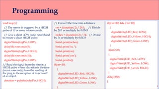
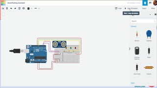
Welcome
to Robotics
Lab Rules
Uniform
Attendance
Class Schedule
Smart Parking
Assistant
Engr. Hassan Mehmood Khan
Robotics Lab Incharge
List of Components
• Arduino UNO
• Breadboard
• Ultrasonic sensor
• LED Traffic Light Module
• Connecting Wires
• Programming Cable
• 9V Battery
• Connecting wires and clips
Arduino UNO
Digital I/O pins – input and output
pins (0 -13) of which 6 of them (3, 5, 6,
9, 10 and 11) also provide PWM (Pulse
Width Modulated) output by using the
analogWrite() function.
Pins (0 (RX) and 1 (TX)) are also used to
transmit and receive serial data.
The microcontroller development
board that will be at the heart of your
projects. It’s a simple computer, but
one that has no way for you to
interact with it yet. You will be
building the circuits and interfaces for
interaction, and telling the
microcontroller how to interface with
other components.
Digital IO
• The digital inputs and outputs (digital I/O) on
the Arduino are what allow you to connect
sensors, actuators, and other ICs to the
Arduino .
• Learning how to use the inputs and outputs will
allow you to use the Arduino to do some really
useful things, such as reading switch inputs,
lighting indicators, and controlling relay
outputs.
• Unlike analog signals, which may take on any
value within a range of values, digital signals
have two distinct values: HIGH (1) or LOW (0).
You use digital signals in situationswhere the
input or output will have one of those two
values. For example, one way that you might
use a digital signal is to turn an LED on or off.
Breadboard
A board on which you can build electronic circuits.
It’s like a patch panel, with rows of holes that allow
you to connect wires and components together.
Versions that require soldering are available, as well
as the solder-less type used here.
Ultrasonic Distance Sensor
RGB LED Module
•Size: 56 * 21 * 11mm
•Color: red, yellow green
•LED: 5mm * 3
•Brightness: Normal
brightness
•Voltage: 5V
•Input: Digital signal output
•Interface: common
cathode red yellow-green
control
Traffic Light Project
Wiring Diagram
Functions
• The Arduino functions
associated with digital
signals that we will be
using are:
• pinMode()
• digitalRead()
• digitalWrite()
pinMode (pin_number, mode)
Because the Arduino digital I/O pins can be used for
either input or output, you should first configure the
pins you intend to use for digital I/O with this
function. pin is the number of the pin you wish to
configure. mode must be one of three values: INPUT,
OUTPUT. (third value we will not discuss here)
digitalWrite(pin_number,value)
This function writes a digital value to a
pin. pin specifies which Arduino pin the digital value
will be written to, and value is the digital value to which
the pin is set. Value must be either HIGH or LOW.
digitalRead(pin_number)
This function reads a digital value from a pin. pin is the
number of the digital I/O pin you want to read. This
function returns one of two values: HIGH or LOW.
Programming
int red = 2;
int yellow = 3;
int green = 4;
void setup(){
pinMode(red, OUTPUT);
pinMode(yellow,
OUTPUT);
pinMode(green, OUTPUT);
}
void loop(){
// green off, yellow on for 3 seconds
digitalWrite(green, LOW);
digitalWrite(yellow, HIGH);
delay(3000);
// turn off yellow, then turn red on for 5
seconds
digitalWrite(yellow, LOW);
digitalWrite(red, HIGH);
delay(5000);
// red and yellow on for 2 seconds (red is
already on though)
digitalWrite(yellow, HIGH);
delay(2000);
// turn off red and yellow, then turn on green
digitalWrite(yellow, LOW);
digitalWrite(red, LOW);
digitalWrite(green, HIGH);
delay(3000);
Programming
• The program consists of four distinct steps:
• Green on, yellow off
• Yellow off, red on
• Yellow on, red on
• Green on, red off, yellow off
• These four steps replicate the process used in real traffic
lights. For each step, the code is very similar. The
appropriate LED gets turned on or off using digitalWrite.
This is an Arduino function used to set output pins to HIGH
(for on), or LOW (for off).
Circuit Diagram
Programming
int trigPin = 2; // Trigger
int echoPin = 3; // Echo
int LED_Red = 10; // Red LED
int LED_Yellow = 8; // Yellow LED
int LED_Green = 9; // Green LED
long duration, cm, inches;
void setup()
{
//Serial Port begin
Serial.begin (9600);
//Define inputs and outputs
pinMode(trigPin, OUTPUT);
pinMode(echoPin, INPUT);
pinMode(LED_Red, OUTPUT);
pinMode(LED_Yellow, OUTPUT);
pinMode(LED_Green, OUTPUT);
digitalWrite(LED_Red, LOW);
digitalWrite(LED_Yellow, LOW);
digitalWrite(LED_Green, LOW);
}
Programming
void loop() {
// The sensor is triggered by a HIGH
pulse of 10 or more microseconds.
// Give a short LOW pulse beforehand
to ensure a clean HIGH pulse:
digitalWrite(trigPin, LOW);
delayMicroseconds(5);
digitalWrite(trigPin, HIGH);
delayMicroseconds(10);
digitalWrite(trigPin, LOW);
// Read the signal from the sensor: a
HIGH pulse whose duration is the time
(in microseconds) from the sending of
the ping to the reception of its echo off
of an object.
duration = pulseIn(echoPin, HIGH);
// Convert the time into a distance
cm = (duration/2) / 29.1; // Divide
by 29.1 or multiply by 0.0343
inches = (duration/2) / 74; // Divide
by 74 or multiply by 0.0135
Serial.print(inches);
Serial.print("in, ");
Serial.print(cm);
Serial.print("cm");
Serial.println();
if(cm<10)
{
digitalWrite(LED_Red, HIGH);
digitalWrite(LED_Yellow, LOW);
digitalWrite(LED_Green, LOW);
}
if((cm<20) && (cm>10))
{
digitalWrite(LED_Red, LOW);
digitalWrite(LED_Yellow, HIGH);
digitalWrite(LED_Green, LOW);
}
if(cm>20)
{
digitalWrite(LED_Red, LOW);
digitalWrite(LED_Yellow, LOW);
digitalWrite(LED_Green, HIGH);
}
delay(250);
}
Simulation
THANK YOU

Lecture2- Smart Parking Assistant using Arduino

  • 1.
  • 2.
  • 3.
    Smart Parking Assistant Engr. HassanMehmood Khan Robotics Lab Incharge
  • 4.
    List of Components •Arduino UNO • Breadboard • Ultrasonic sensor • LED Traffic Light Module • Connecting Wires • Programming Cable • 9V Battery • Connecting wires and clips
  • 5.
    Arduino UNO Digital I/Opins – input and output pins (0 -13) of which 6 of them (3, 5, 6, 9, 10 and 11) also provide PWM (Pulse Width Modulated) output by using the analogWrite() function. Pins (0 (RX) and 1 (TX)) are also used to transmit and receive serial data. The microcontroller development board that will be at the heart of your projects. It’s a simple computer, but one that has no way for you to interact with it yet. You will be building the circuits and interfaces for interaction, and telling the microcontroller how to interface with other components.
  • 6.
    Digital IO • Thedigital inputs and outputs (digital I/O) on the Arduino are what allow you to connect sensors, actuators, and other ICs to the Arduino . • Learning how to use the inputs and outputs will allow you to use the Arduino to do some really useful things, such as reading switch inputs, lighting indicators, and controlling relay outputs. • Unlike analog signals, which may take on any value within a range of values, digital signals have two distinct values: HIGH (1) or LOW (0). You use digital signals in situationswhere the input or output will have one of those two values. For example, one way that you might use a digital signal is to turn an LED on or off.
  • 7.
    Breadboard A board onwhich you can build electronic circuits. It’s like a patch panel, with rows of holes that allow you to connect wires and components together. Versions that require soldering are available, as well as the solder-less type used here.
  • 8.
  • 9.
    RGB LED Module •Size:56 * 21 * 11mm •Color: red, yellow green •LED: 5mm * 3 •Brightness: Normal brightness •Voltage: 5V •Input: Digital signal output •Interface: common cathode red yellow-green control
  • 10.
  • 11.
  • 12.
    Functions • The Arduinofunctions associated with digital signals that we will be using are: • pinMode() • digitalRead() • digitalWrite() pinMode (pin_number, mode) Because the Arduino digital I/O pins can be used for either input or output, you should first configure the pins you intend to use for digital I/O with this function. pin is the number of the pin you wish to configure. mode must be one of three values: INPUT, OUTPUT. (third value we will not discuss here) digitalWrite(pin_number,value) This function writes a digital value to a pin. pin specifies which Arduino pin the digital value will be written to, and value is the digital value to which the pin is set. Value must be either HIGH or LOW. digitalRead(pin_number) This function reads a digital value from a pin. pin is the number of the digital I/O pin you want to read. This function returns one of two values: HIGH or LOW.
  • 13.
    Programming int red =2; int yellow = 3; int green = 4; void setup(){ pinMode(red, OUTPUT); pinMode(yellow, OUTPUT); pinMode(green, OUTPUT); } void loop(){ // green off, yellow on for 3 seconds digitalWrite(green, LOW); digitalWrite(yellow, HIGH); delay(3000); // turn off yellow, then turn red on for 5 seconds digitalWrite(yellow, LOW); digitalWrite(red, HIGH); delay(5000); // red and yellow on for 2 seconds (red is already on though) digitalWrite(yellow, HIGH); delay(2000); // turn off red and yellow, then turn on green digitalWrite(yellow, LOW); digitalWrite(red, LOW); digitalWrite(green, HIGH); delay(3000);
  • 14.
    Programming • The programconsists of four distinct steps: • Green on, yellow off • Yellow off, red on • Yellow on, red on • Green on, red off, yellow off • These four steps replicate the process used in real traffic lights. For each step, the code is very similar. The appropriate LED gets turned on or off using digitalWrite. This is an Arduino function used to set output pins to HIGH (for on), or LOW (for off).
  • 15.
  • 16.
    Programming int trigPin =2; // Trigger int echoPin = 3; // Echo int LED_Red = 10; // Red LED int LED_Yellow = 8; // Yellow LED int LED_Green = 9; // Green LED long duration, cm, inches; void setup() { //Serial Port begin Serial.begin (9600); //Define inputs and outputs pinMode(trigPin, OUTPUT); pinMode(echoPin, INPUT); pinMode(LED_Red, OUTPUT); pinMode(LED_Yellow, OUTPUT); pinMode(LED_Green, OUTPUT); digitalWrite(LED_Red, LOW); digitalWrite(LED_Yellow, LOW); digitalWrite(LED_Green, LOW); }
  • 17.
    Programming void loop() { //The sensor is triggered by a HIGH pulse of 10 or more microseconds. // Give a short LOW pulse beforehand to ensure a clean HIGH pulse: digitalWrite(trigPin, LOW); delayMicroseconds(5); digitalWrite(trigPin, HIGH); delayMicroseconds(10); digitalWrite(trigPin, LOW); // Read the signal from the sensor: a HIGH pulse whose duration is the time (in microseconds) from the sending of the ping to the reception of its echo off of an object. duration = pulseIn(echoPin, HIGH); // Convert the time into a distance cm = (duration/2) / 29.1; // Divide by 29.1 or multiply by 0.0343 inches = (duration/2) / 74; // Divide by 74 or multiply by 0.0135 Serial.print(inches); Serial.print("in, "); Serial.print(cm); Serial.print("cm"); Serial.println(); if(cm<10) { digitalWrite(LED_Red, HIGH); digitalWrite(LED_Yellow, LOW); digitalWrite(LED_Green, LOW); } if((cm<20) && (cm>10)) { digitalWrite(LED_Red, LOW); digitalWrite(LED_Yellow, HIGH); digitalWrite(LED_Green, LOW); } if(cm>20) { digitalWrite(LED_Red, LOW); digitalWrite(LED_Yellow, LOW); digitalWrite(LED_Green, HIGH); } delay(250); }
  • 18.
  • 19.