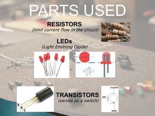
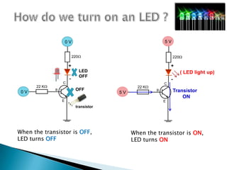
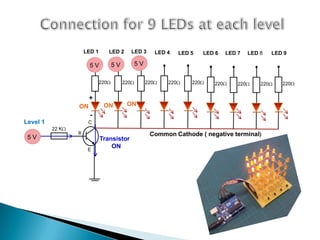
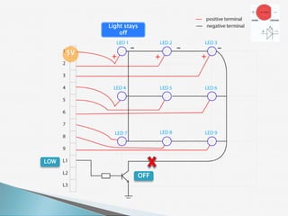
The document provides a detailed overview of using an Arduino micro-controller board, including setup instructions and example code for controlling LEDs and transistors. It describes various components, programming concepts like loops and arrays, and outlines how to connect and program the board using a free software platform. Key functions, such as 'setup()' and 'loop()', illustrate the basic structure of an Arduino sketch.


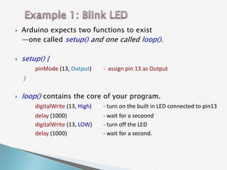
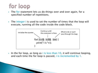
![Number of
variables
int LevelPin [3] = { 10, 11, 12 };
Type of array
Name of List of variables
content
the array
i.e LevelPin [0] = 10
LevelPin [1] = 11
LevelPin [2] = 12](https://image.slidesharecdn.com/ledcubeslides-120803001649-phpapp02/85/LED-Cube-Presentation-Slides-24-320.jpg)
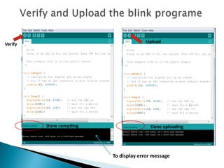
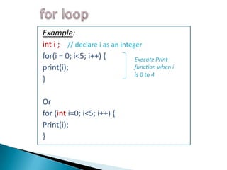
![Another great use of the for loop is to go through an array
and look at each item in the array:
for ( int level=0; level <3; level++)
{ pinMode (LevelPin[level], OUTPUT ); }
Each time the loop executes, level will be incremented using
the next integer in the Array[ ]
pinMode (LevelPin[0], OUTPUT );
pinMode (LevelPin[1], OUTPUT );
pinMode (LevelPin[2], OUTPUT );](https://image.slidesharecdn.com/ledcubeslides-120803001649-phpapp02/85/LED-Cube-Presentation-Slides-25-320.jpg)
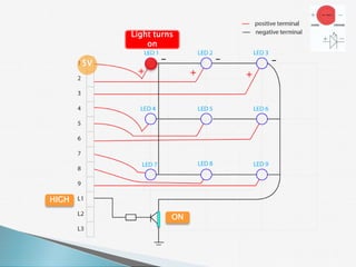
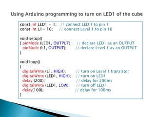
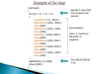
![for (level=0; level< 3; level++)
{
digitalWrite ( LevelPin[level], HIGH );
digitalWrite ( LED1, HIGH );
digitalWrite ( LED2, HIGH );
:
:
digitalWrite ( LED9, HIGH );
delay (100);
digitalWrite ( LED1, LOW );
digitalWrite ( LED2, LOW );
:
:
digitalWrite ( LED9, LOW );
digitalWrite ( LevelPin[level], LOW );
delay(50);
}](https://image.slidesharecdn.com/ledcubeslides-120803001649-phpapp02/85/LED-Cube-Presentation-Slides-26-320.jpg)