This document provides standards for Computer Aided Drafting (CAD) drawings for a hospital project in Peshawar, Pakistan. It establishes guidelines for sheet numbering, file naming, scale, text, dimensions, blocks/details, revisions, and deliverables. Standards are defined for layer naming conventions, units of measure, scales, text styles, dimensioning, CADD parameters and templates to maintain consistent, clear and organized CAD drawings. It aims to allow different personnel to easily share, review and maintain project documentation.

![21
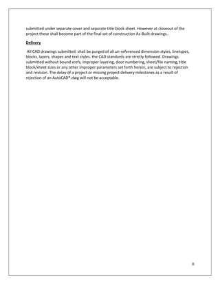
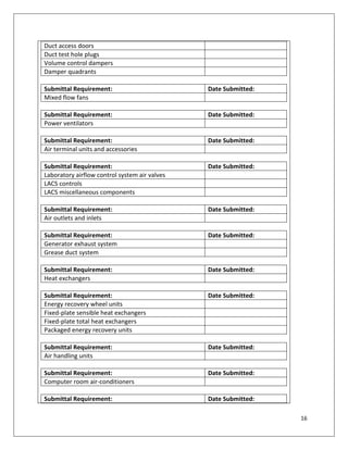
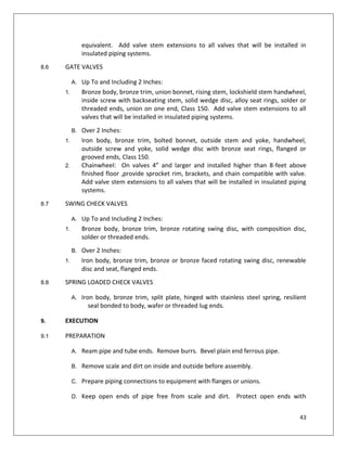
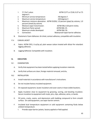
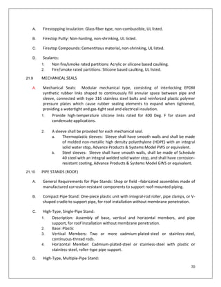
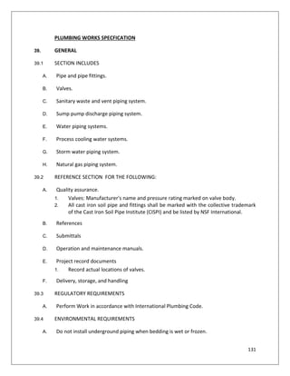
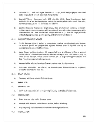
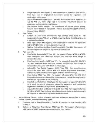
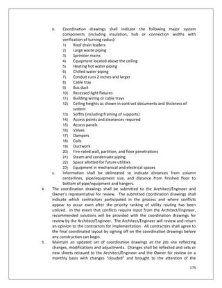
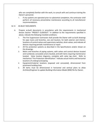
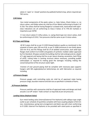
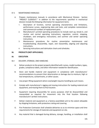
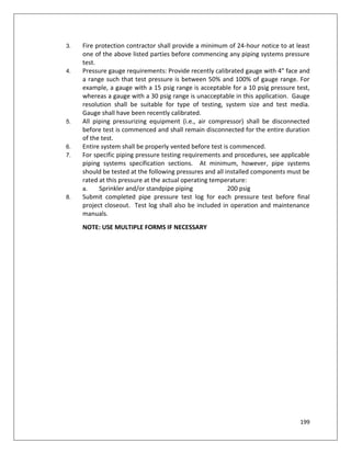
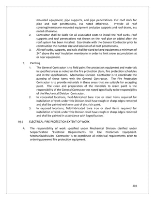
1.35 Material or equipment damaged, shown to be defective or not in accordance with the
Specifications shall be repaired or replaced to the satisfaction of the Owner’s
representative.
1.36 All tests shall be made after notification to and in the presence of the Owner’s
representative.
1.37 Before starting up any system, each piece of equipment comprising any part of the
system shall be checked for proper lubrication and any other condition which may
cause damage to the equipment or endanger personnel.
1.38 After systems have been demonstrated to be satisfactory for 7 consecutive days and
ready for permanent operation, all permanent pipe line strainers shall be cleaned,
valve and packings properly adjusted, lubrication checked and replenished if required.
Temporary piping, etc. shall be removed and openings restored in a permanent
manner acceptable to the Owner’s representative.
1.39 Conduct a walk-through instruction seminar for the Owner's personnel pertaining to
the continued operation and maintenance of mechanical equipment and systems.
Explain the identification system, maintenance requirements, operational diagrams,
temperature control provisions, sequencing requirements, security, safety, efficiency
and similar features of the systems. Walk through must be documented as to those
attending and subjects covered. Walk through document(s) shall be signed and dated
by the contractor's representative and the owner's representative.
1. [Note to A/E: List all HVAC systems that require walk through instructional
seminar]
B. At the time of substantial project completion, turn over the prime responsibility for
operation of the mechanical equipment and systems to the Owner's operating
personnel. Until the time of final acceptance, provide full time operating personnel,
who are completely familiar with the work, to consult with and continue training the
Owner's personnel. If any systems are operated prior to substantial completion, the
contractor shall perform all necessary preventative maintenance according to all
manufacturer recommendations.
1.40 RECORD DOCUMENTS
A. Prepare as-built documents in accordance with the requirements in mechanical
Division "PROJECT CLOSEOUT." In addition to the requirements specified in above,
indicate the following installed conditions:
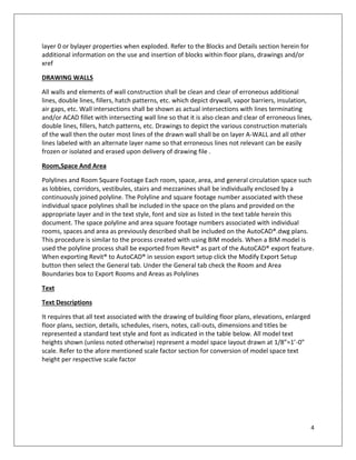
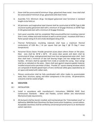
1. The Mechanical Contractor shall provide the Owner with as-built drawings for
ductwork mains and branches, size and location, for both exterior and interior;
locations of dampers and other control devices; filters, boxes, and terminal units
and indicate all devices requiring periodic maintenance or repair, such as control
power transformers, LACS panels/routers, field controllers, duct static pressure](https://image.slidesharecdn.com/phplmepspecs-181016075610/85/Technical-Specification-MEP-Works-21-320.jpg)
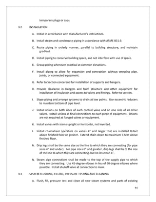
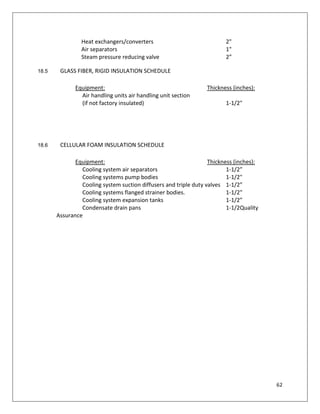
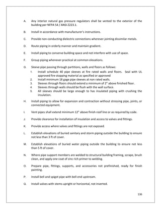
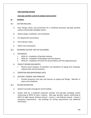
![22
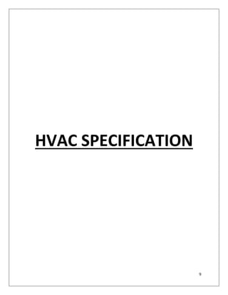
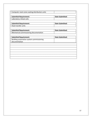
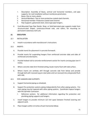
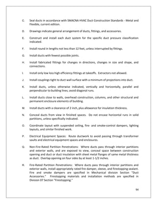
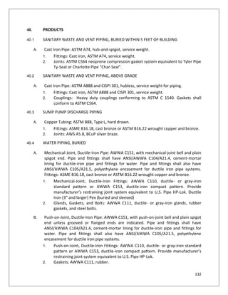
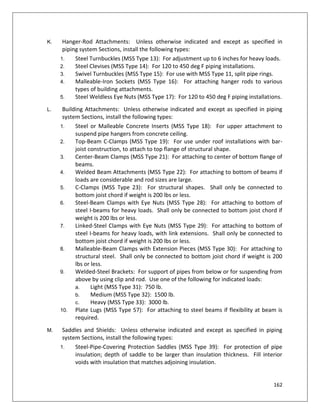
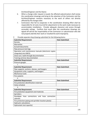
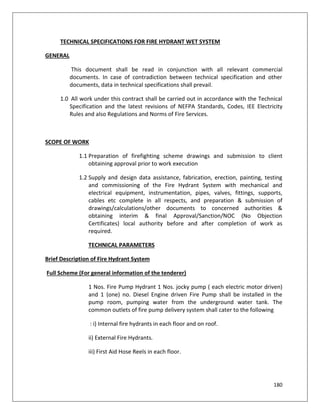
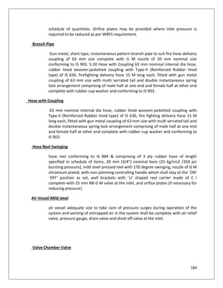
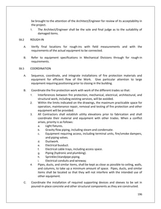
sensors, piping pressure sensors, etc.
2. All mechanical systems as described in the Specifications and/or shown on the
drawings.
3. Mains and branches of piping systems, with valves and control devices located
and numbered, concealed unions located, and with items requiring maintenance
located (i.e., traps, strainers, expansion compensators, tanks, etc.). Valve
location diagrams, complete with valve tag chart. Refer to Section "Mechanical
Identification." Indicate actual inverts and horizontal locations of underground
piping.
4. Equipment/material locations (exposed and concealed), dimensioned from
prominent building lines.
1.41 MAINTENANCE MANUALS
A. Prepare maintenance manuals in accordance with mechanical division "PROJECT
CLOSEOUT." In addition to the requirements specified in mechanical division, include
the following information for equipment items:
1. Description of function, normal operating characteristics and limitations,
performance curves, engineering data and tests, and complete nomenclature
and commercial numbers of replacement parts.
2. Manufacturer's printed operating procedures to include start-up, break-in, and
routine and normal operating instructions; regulation, control, stopping,
shutdown, and emergency instructions; and summer and winter operating
instructions.
3. Maintenance procedures for routine preventative maintenance and
troubleshooting; disassembly, repair, and reassembly; aligning and adjusting
instructions.
4. Servicing instructions and lubrication charts and schedules.
B. Provide electronic copies, preferably in Adobe Acrobat Portable Document Format
(pdf), of all maintenance manuals to Temperature Control Contractor for use in EMCS
front-end system. Provide data in file types compatible with EMCS.
2. PRODUCTS (NOT APPLICABLE TO PHPL PROJECT).
3. EXECUTION
3.1 MECHANICAL DEMOLITION
[Note to A/E: Revise this section as necessary to address actual project requirements]
Refer to Division Sections for general demolition requirements and procedures.](https://image.slidesharecdn.com/phplmepspecs-181016075610/85/Technical-Specification-MEP-Works-22-320.jpg)
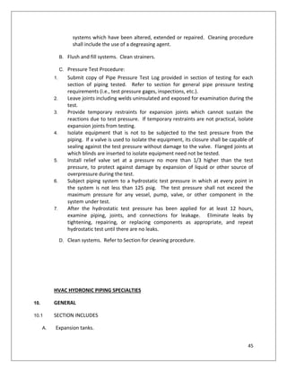
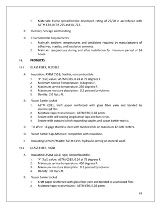
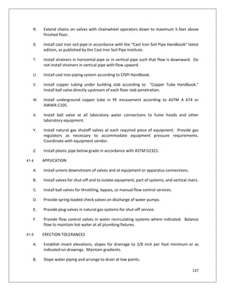
![33
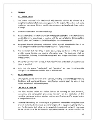
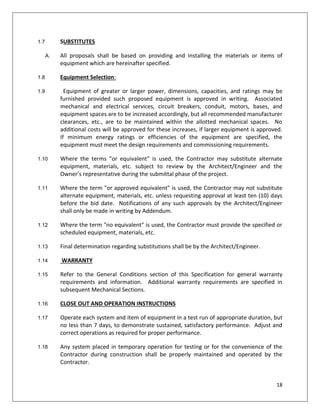
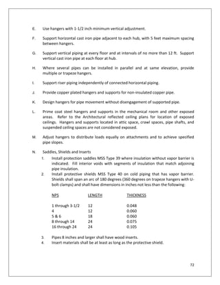
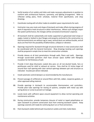
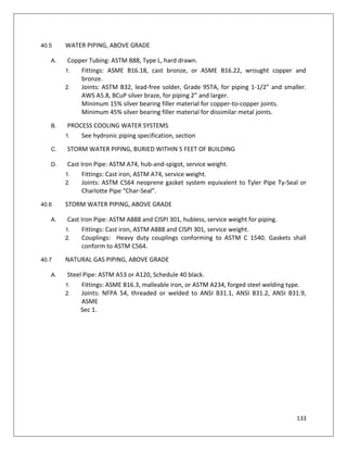
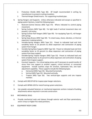
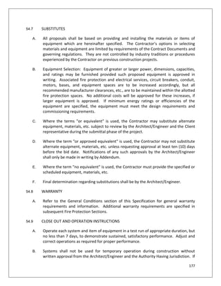
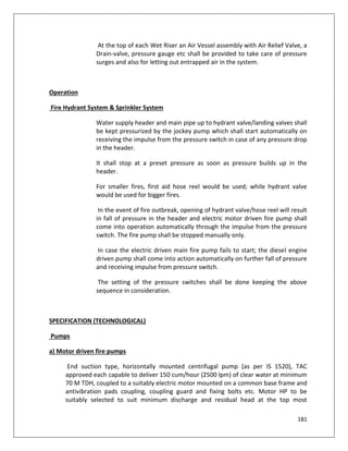
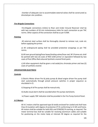
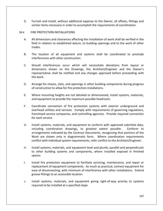
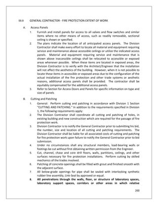
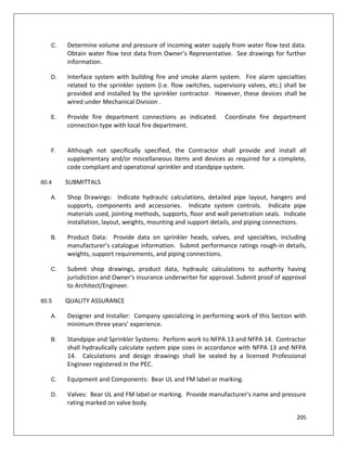
1. Lubricate bearings.
2. Check, align and certify alignment of base mounted pumps prior to start-up.
3. After pump is started, check for proper rotation, proper mechanical operation
and motor load to ensure that pump is not overloaded. Close pump balancing
valve as required to bring pump motor load within motor nameplate data.
4. Check pumps to ensure it is not air bound or cavitating.
5. After sufficient run time, remove, check and clean strainer as required. Repeat
cleaning strainer until system is sufficiently flushed. Refer to Section 23 25 00,
Chemical Water Treatment.
6. After completing start-up, replace pump strainer with permanent strainer.
C. Coordinate pump testing, adjusting and balancing with UNL Balancing / Commissioning
Team. Complete additional preliminary work as required.
HVAC Hydronic piping syatem
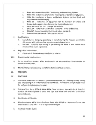
5. GENERAL
5.1 SECTION INCLUDES
[Note: Edit following section to include/exclude actual project hydronic systems]
A. Above grade pipe, fittings, and joints for:
1. Heating water piping systems.
2. Chilled water piping systems.
3. Heat pump water piping systems.
4. Heat recovery water piping systems.
5. Equipment drains and overflows.
6. Process cooling water systems.
B. Valves.
5.2 REFERENCE SECTION FOR THE FOLLOWING:
A. Quality assurance.
B. References.
C. Submittals.
D. Operation and maintenance manuals.
E. Project record documents.
1. Record actual locations of valves.](https://image.slidesharecdn.com/phplmepspecs-181016075610/85/Technical-Specification-MEP-Works-33-320.jpg)
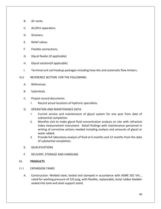
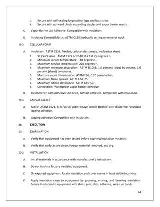
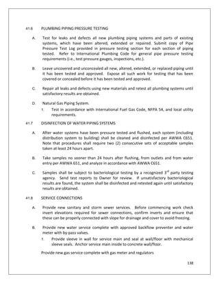
![49
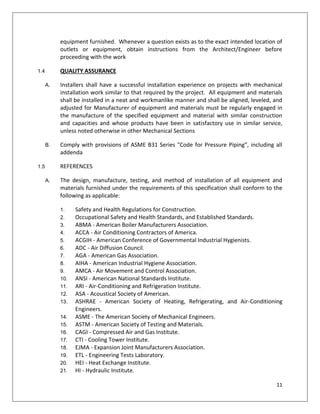
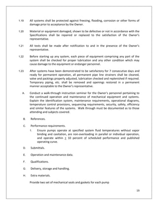
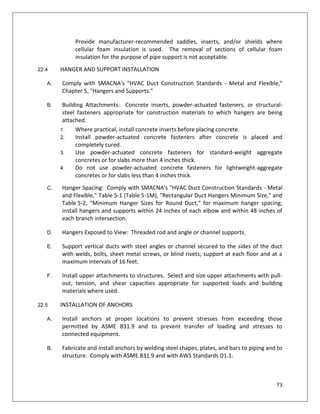
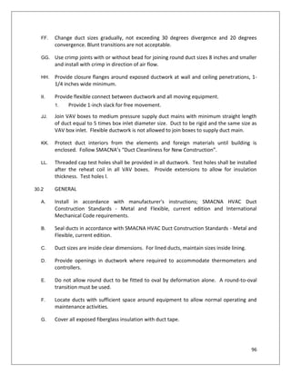
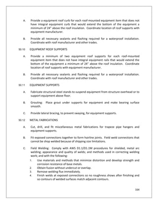
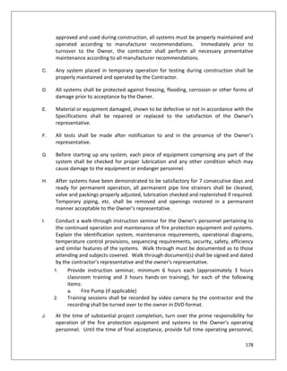
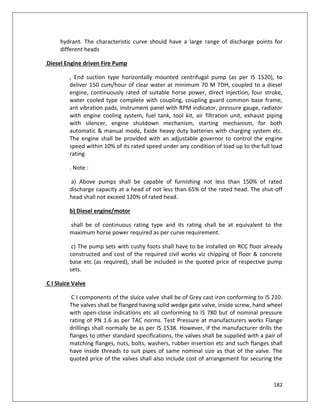
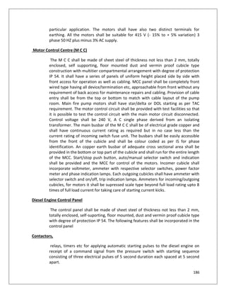
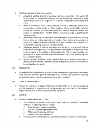
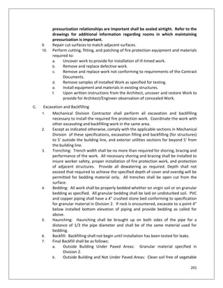
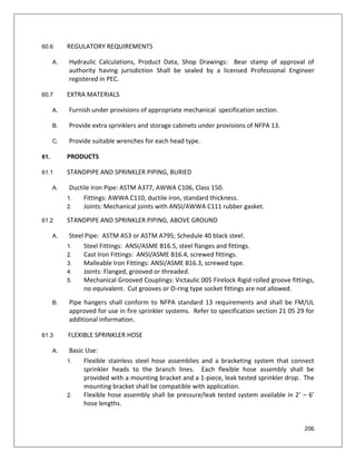
B. Control Panel: NEMA 4X with 2-position main power switch and light, 3-position,
hand-off-auto, switch and light for gear pump, red low light and 15 A fuse.
C. Low Level Switch: Polypropylene side entry low level switch with 10 A relay.
D. Gear Pump: Includes PVC ball valve, flexible tubing and cast iron Y-strainer. Pump
discharge tubing includes brass construction spring check valve, PVC piping, and ¼”
NPT back tap pressure gauge.
E. Pressure Switch: ¼” NPT
F. Pressure Relief Valves: 50-250 PSI brass valve
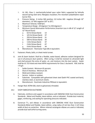
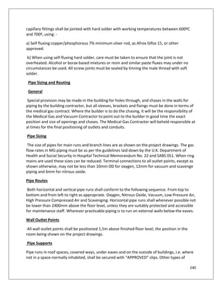
11.8 GLYCOL SOLUTION
[Note to A/E: Edit glycol percentages based on project needs. Provide percentage
schedule if multiple hydronic systems are involved]
A. Inhibited propylene glycol and water solution mixed [50] percent glycol - [50] percent
water, suitable for operating temperatures from [-40] degrees F to 250 degrees F.
11.9 TERMINAL UNIT COIL HOOKUP
A. The components specified in this section shall be installed on the following devices:
1. Air terminal unit reheat coils.
2. Fintubes
3. Unit heaters
4. Cabinet unit heaters
5. Fan coils
6. Radiant ceiling panels
7. Chilled beams
8. Small (1-5 Ton), unitary, water source heat pumps.
B. Acceptable Manufacturers
1. Griswold
2. Pro Hydronics
3. Flow Design
4. Nexus
C. Piping package components
1. Automatic flow limiter
a. Shall have the capability to measure flow.
b. Automatic flow limiting cartridge(s) will be made of stainless steel. No
brass or plastic components allowed.
c. Flow rate accuracy will be +/- 5% of design flow rate.
d. Shall be of a pressure independent, clog resistant design.](https://image.slidesharecdn.com/phplmepspecs-181016075610/85/Technical-Specification-MEP-Works-49-320.jpg)
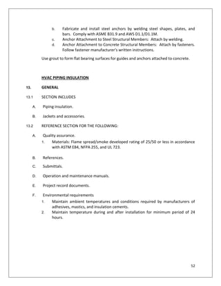
![61
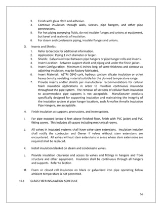
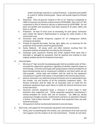
2. Finish with glass cloth and vapor barrier adhesive.
3. Insulate entire system.
G. For insulated equipment containing fluids above ambient temperature:
H. Provide standard jackets, with or without vapor barrier, factory applied or field
applied.
1. Finish with glass cloth and adhesive.
2. For hot equipment containing fluids do not insulate flanges and unions, but
bevel and seal ends of insulation.
I. Inserts and Shields:
1. Application: equipment 1-1/2 inches diameter or
larger.
2. Shields: galvanized steel between hangers and
inserts.
3. Insert location: between support shield and equipment and under the
finish jacket.
4. Insert configuration: minimum 6 inches long, of same thickness and contour as
adjoining insulation; may be factory fabricated.
5. Insert material: ASTM C640 cork, hydrous calcium silicate insulation or other
heavy density insulating material suitable for the planned temperature range.
J. Finish insulation at supports, protrusions, and interruptions.
K. For equipment in mechanical equipment rooms or in finished spaces, finish with
canvas jacket sized for finish covering.
L. Do not insulate over nameplate or ASME stamps. Bevel and seal insulation around
such labeling.
M. Install insulation for equipment requiring access for maintenance, repair, or cleaning,
in such a manner that it can be easily removed and replaced without damage.
18.3 TOLERANCE
A. Substituted insulation materials shall provide thermal resistance within 10 percent at
normal conditions, as materials indicated.
[Note to A/E: Edit Equipment Insulation Schedules as necessary to suit project
requirements]
18.4 GLASS FIBER, FLEXIBLE INSULATION SCHEDULE
A. Heating Systems
Equipment: Thickness (inches):](https://image.slidesharecdn.com/phplmepspecs-181016075610/85/Technical-Specification-MEP-Works-61-320.jpg)
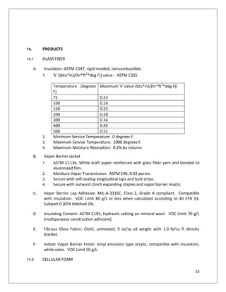
![65
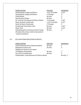
E. Fill joints, cracks, seams, and depressions with bedding compound to form smooth
surface. On cold equipment, use vapor barrier cement.
F. Insulated dual temperature equipment or cold equipment containing fluids below
ambient temperature:
1. Provide vapor barrier jackets, factory applied or field applied.
2. Finish with glass cloth and vapor barrier adhesive.
3. Insulate entire system.
G. For insulated equipment containing fluids above ambient temperature:
H. Provide standard jackets, with or without vapor barrier, factory applied or field
applied.
1. Finish with glass cloth and adhesive.
2. For hot equipment containing fluids do not insulate flanges and unions, but
bevel and seal ends of insulation.
3.
I. Inserts and Shields:
1. Application: equipment 1-1/2 inches diameter or larger.
2. Shields: galvanized steel between hangers and inserts.
3. Insert location: between support shield and equipment and under the finish
jacket.
4. Insert configuration: minimum 6 inches long, of same thickness and contour as
adjoining insulation; may be factory fabricated.
5. Insert material: ASTM C640 cork, hydrous calcium silicate insulation or other
heavy density insulating material suitable for the planned temperature range.
J. Finish insulation at supports, protrusions, and interruptions.
K. For equipment in mechanical equipment rooms or in finished spaces, finish with
canvas jacket sized for finish covering.
L. Do not insulate over nameplate or ASME stamps. Bevel and seal insulation around
such labeling.
M. Install insulation for equipment requiring access for maintenance, repair, or cleaning,
in such a manner that it can be easily removed and replaced without damage.
20.3 TOLERANCE
A. Substituted insulation materials shall provide thermal resistance within 10 percent at
normal conditions, as materials indicated.
[Note to A/E: Edit Equipment Insulation Schedules as necessary to suit project
requirements]](https://image.slidesharecdn.com/phplmepspecs-181016075610/85/Technical-Specification-MEP-Works-65-320.jpg)
![79
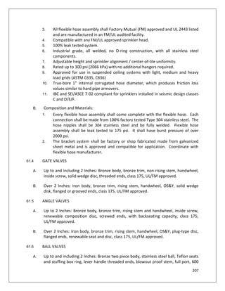
G. Accuracy: Plus or minus 1 percent of range span or plus or minus one scale division to
maximum of 1.5 percent of range span.
H. Scale range: Temperature ranges for services listed as follows:
1. Condenser/Heat Pump Water: 0 to 160 deg F with 2-degree scale divisions
(minus 18 to 70 deg C with 1-degree scale divisions).
2. Heating Water: 30 to 250 deg with 2-degree scale divisions (0 to 150 deg C with
1-degree scale divisions).
3. Chilled Water: 0 to 100 deg F with 2-degree scale divisions (minus 20 to 50 deg C
with 1-degree scale divisions).
4. Steam and Condensate: 50 to 400 deg F with 2-degree scale divisions (0 to 200
deg C with 1-degree scale divisions).
23.5 THERMOMETER WELLS
A. Thermometer Wells: Brass or stainless steel, pressure rated to match piping system
design pressure; with 2-inch extension for insulated piping and threaded cap nut with
chain permanently fastened to well and cap.
23.6 PIPING PRESSURE AND TEMPERATURE TEST PLUGS
A. Test Plugs shall be nickel-plated brass body, with 1/2-inch NPS fitting and 2 self-sealing
valve-type core inserts, suitable for inserting a 1/8-inch O.D. probe assembly from a
dial-type thermometer or pressure gage. Test plug shall have gasketed and threaded
cap with retention chain and body of length to extend beyond insulation. Pressure
rating shall be 500 psig.
B. Core Material: Conform to the following for fluid and temperature range:
1. Air, Water, Oil, and Gas, 20 to 200 deg F (minus 7 to 93 deg C): Neoprene.
23.7 STATIC PRESSURE GAGES
A. Inclined manometer, red liquid on white background with black figures, front
recalibration adjustment, 3 percent of full scale accuracy.
B. Accessories: Static pressure tips with compression fittings for bulkhead mounting, 1/4
inch (6 mm) diameter tubing.
C. Construction: Bronze or stainless-steel body, with sight glass and [ball, flapper, or
paddle wheel] <Insert device> indicator, and threaded or flanged ends.
D. Minimum Pressure Rating: [125 psig (860 kPa)] [150 psig (1034 kPa)] <Insert value>.](https://image.slidesharecdn.com/phplmepspecs-181016075610/85/Technical-Specification-MEP-Works-79-320.jpg)
![80
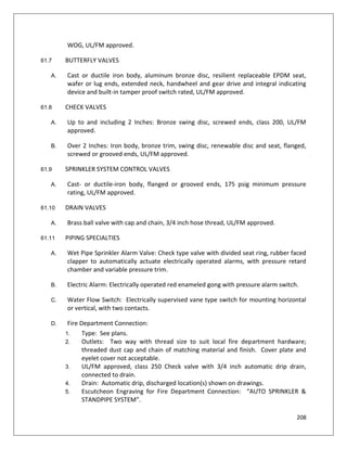
E. Minimum Temperature Rating: [200 deg F (93 deg C)] <Insert temperature>.
F. End Connections for NPS 2 (DN 50) and Smaller: Threaded.
G. End Connections for NPS 2-1/2 (DN 65) and Larger: Flanged.
24. EXECUTION
24.1 GENERAL
A. Install in accordance with manufacturer's instructions.
24.2 FLOW MEASURING METERS
A. Install where shown on plans and schematics as indicated.
B. Assemble and install connections, tubing, and accessories between flow-measuring
elements and flowmeters according to manufacturer's written instructions and as
detailed on drawings.
C. Install flowmeter elements in accessible positions in piping systems. Maintain
manufacturer-recommended minimum upstream and downstream distances.
D. Install permanent indicators on walls or brackets in accessible and readable positions.
E. Install connection fittings in accessible locations for attachment to portable indicators.
F. Mount thermal-energy meters on wall if accessible; if not, provide brackets to support
meters.
G. Install flow meters for piping systems located in accessible locations at most readable
position.
H. Calibrate meter after installation in accordance with manufacturer's installation
instructions.
I. Installation of steam meter and associated wiring, pressure transmitter and RTD
assembly, shall be in strict accordance with manufacturer’s printed instructions and
recommendations, applicable requirements, and as detailed on drawings.
J. Pressure and temperature taps shall be installed a minimum of three pipe diameters
downstream, before any isolation valves.
K. Steam will not be turned on by client personnel until the steam meter is fully installed
and operating satisfactorily and the downstream steam piping is successfully leak
tested and secure.](https://image.slidesharecdn.com/phplmepspecs-181016075610/85/Technical-Specification-MEP-Works-80-320.jpg)
![85
H. Scale range: Temperature ranges for services listed as follows:
1. Condenser/Heat Pump Water: 0 to 160 deg F with 2-degree scale divisions
(minus 18 to 70 deg C with 1-degree scale divisions).
2. Heating Water: 30 to 250 deg with 2-degree scale divisions (0 to 150 deg C with
1-degree scale divisions).
3. Chilled Water: 0 to 100 deg F with 2-degree scale divisions (minus 20 to 50 deg C
with 1-degree scale divisions).
4. Steam and Condensate: 50 to 400 deg F with 2-degree scale divisions (0 to 200
deg C with 1-degree scale divisions).
26.5 THERMOMETER WELLS
A. Thermometer Wells: Brass or stainless steel, pressure rated to match piping system
design pressure; with 2-inch extension for insulated piping and threaded cap nut with
chain permanently fastened to well and cap.
B.
26.6 PIPING PRESSURE AND TEMPERATURE TEST PLUGS
A. Test Plugs shall be nickel-plated brass body, with 1/2-inch NPS fitting and 2 self-sealing
valve-type core inserts, suitable for inserting a 1/8-inch O.D. probe assembly from a
dial-type thermometer or pressure gage. Test plug shall have gasketed and threaded
cap with retention chain and body of length to extend beyond insulation. Pressure
rating shall be 500 psig.
B. Core Material: Conform to the following for fluid and temperature range:
1. Air, Water, Oil, and Gas, 20 to 200 deg F (minus 7 to 93 deg C): Neoprene.
26.7 STATIC PRESSURE GAGES
A. Inclined manometer, red liquid on white background with black figures, front
recalibration adjustment, 3 percent of full scale accuracy.
B. Accessories: Static pressure tips with compression fittings for bulkhead mounting, 1/4
inch (6 mm) diameter tubing.
C. Construction: Bronze or stainless-steel body, with sight glass and [ball, flapper, or
paddle wheel] <Insert device> indicator, and threaded or flanged ends.
D. Minimum Pressure Rating: [125 psig (860 kPa)] [150 psig (1034 kPa)] <Insert value>.
E. Minimum Temperature Rating: [200 deg F (93 deg C)] <Insert temperature>.
F. End Connections for NPS 2 (DN 50) and Smaller: Threaded.](https://image.slidesharecdn.com/phplmepspecs-181016075610/85/Technical-Specification-MEP-Works-85-320.jpg)
![99
finish as exposed duct. Note that exposed ductwork shall be provided with a No.
4 finish. Verify acceptable appearance of installed ductwork with Architect after
installation.
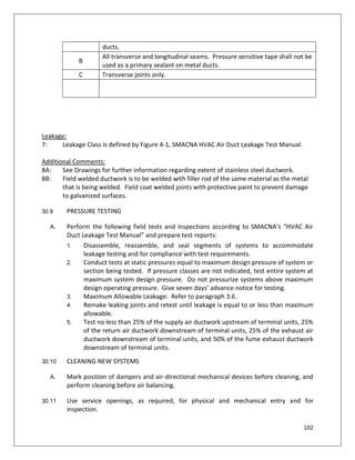
30.7 CLEANING
A. The air handling units, energy recovery wheel, exhaust fans, and other HVAC airside
equipment shall not be used for temporary building conditioning without the written
permission from the Owner and Architect/Engineer. Open ductwork that has been
installed shall be protected during the duration of the project with polyethylene plastic
and duct tape over the open ends. Uninstalled ductwork shall be protected from
construction dust by covering the uninstalled ductwork with polyethylene plastic.
Prior to installing ductwork, the inside of the ductwork shall be wiped down or
vacuumed.
B. Clean inside all air handling units, energy recovery units, and outside air duct systems
before the fans are turned on. Call for inspection by the owner’s representative to
verify that all ducts are cleaned. If the ductwork is unacceptable, the contractor shall
provide vacuuming of these duct systems by forcing air at high velocity through duct
where manual cleaning in not possible due to duct lengths or size. Call for re-
inspection by Owner's representative.
C. Protect equipment which may be harmed by excessive dirt with temporary filters, or
bypass during cleaning.
D. Call for inspection by Owner's representative.
E. Install a fresh set of filters in all equipment immediately prior to project turnover.
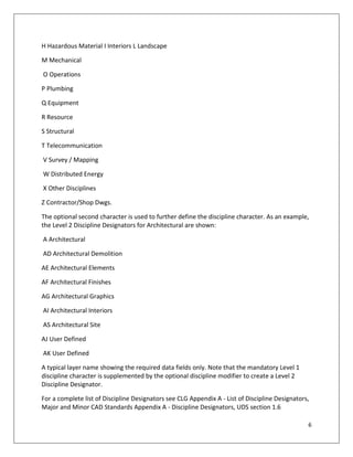
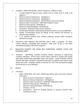
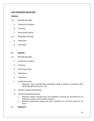
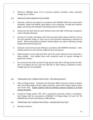
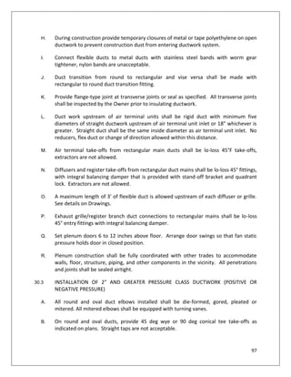
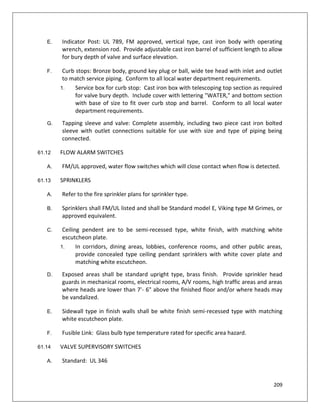
30.8 DUCTWORK SCHEDULE
[Note to A/E: Check and revise pressure class column in Ductwork Schedule based on
project specific requirements]
Duct System:
Materi
al:
Longitudin
al Joints:
Transvers
e Joints:
Pressur
e Class:
Sealan
t
Class:
Leakage
Class:
Additiona
l Notes:
Outside air
system upstream
of AHU
Galv.
Steel
3A 4A, 4C -2” B 24
Rectangular SA Galv. 3A, 3E 4A, 4C, 4D +4” A 6 8B](https://image.slidesharecdn.com/phplmepspecs-181016075610/85/Technical-Specification-MEP-Works-99-320.jpg)
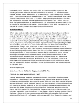
![109
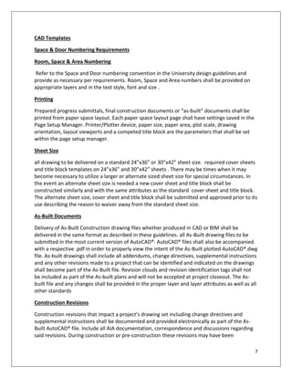
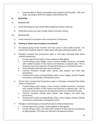
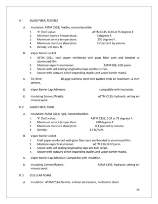
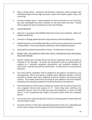
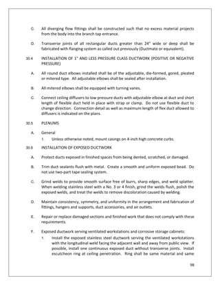
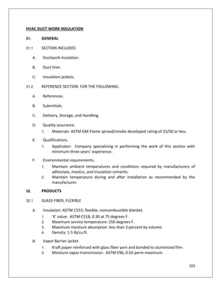
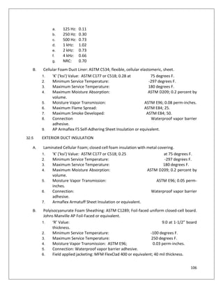
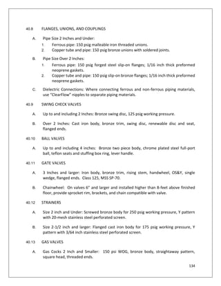
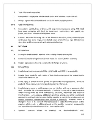
33.3 GLASS FIBER DUCTWORK INSULATION SCHEDULE
[Note to A/E: Edit Duct Insulation Schedule as necessary to suit project requirements]
Ductwork Application: Type: Thickness:
Vapor Barrier
Required (Y/N):
Exposed rectangular outside air duct in
mechanical rooms and chases
Rigid 2” Y
Exposed rectangular supply air duct in
mechanical rooms and chases
Rigid 2” Y
Exposed round supply air duct in mechanical
rooms
Flexible 2” Y
Exposed rectangular and round return air
duct in mechanical rooms
None required unless shown on plans
Exposed rectangular and round exhaust air
duct upstream of heat recovery system in
mechanical rooms
None required unless shown on plans
Exposed rectangular and round exhaust/relief
air duct downstream of heat recovery system
in mechanical rooms
Rigid 2” Y
Exposed rectangular and round return air
duct or exhaust air duct in other areas
None required unless shown on plans
Exposed rectangular and round supply air
duct upstream of terminal units
Flexible 2” Y
Exposed rectangular supply air duct
downstream of terminal units
Flexible 2” Y
Exposed round supply air duct downstream of
terminal units
Flexible 2” Y
Concealed rectangular and round supply air
duct upstream of terminal units
Flexible 2” Y
Concealed rectangular supply air duct
downstream of terminal units
Flexible 2” Y
Concealed round supply air duct downstream
of terminal units
Flexible 2” Y
Concealed return air duct upstream of
terminal units
Liner 1” Y
Concealed exhaust air duct None required unless shown on plans
Return air grille boots/transfer ducts (where
indicated on drawings)
Liner 1” N
Exterior Ductwork Exterior 2” Y](https://image.slidesharecdn.com/phplmepspecs-181016075610/85/Technical-Specification-MEP-Works-109-320.jpg)

![111
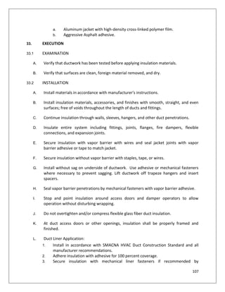
SECTION 23 07 13 - DUCTWORK INSULATION
1. GENERAL
1.1 SECTION INCLUDES
A. Ductwork insulation.
B. Duct liner.
C. Insulation jackets.
1.2 REFERENCE SECTION FOR THE FOLLOWING:
A. References.
B. Submittals.
C. LEED Submittals:
[Note to A/E: Edit to suit any LEED certification requirements]
D. Delivery, Storage, and Handling.
E. Quality assurance.
1. Materials: ASTM E84 Flame spread/smoke developed rating of 25/50 or less.
F. Qualifications.
1. Applicator: Company specializing in performing the work of this section with minimum three
years’ experience.
G. Environmental requirements.
1. Maintain ambient temperatures and conditions required by manufacturers of adhesives,
mastics, and insulation cements.
2. Maintain temperature during and after installation as recommended by the manufacturer.
2. PRODUCTS
2.1 GLASS FIBER, FLEXIBLE
A. Insulation: ASTM C553; flexible, noncombustible blanket.
1. 'K' value: ASTM C518, 0.30 at 75 degrees F.
2. Maximum service temperature: 250 degrees F.
3. Maximum moisture absorption: less than 3 percent by volume.
4. Density: 1.5 lb/cu ft.
B. Vapor Barrier Jacket
1. Kraft paper reinforced with glass fiber yarn and bonded to aluminized film.
2. Moisture vapor transmission: ASTM E96; 0.02 perm maximum.
3. Secure with pressure sensitive tape.](https://image.slidesharecdn.com/phplmepspecs-181016075610/85/Technical-Specification-MEP-Works-111-320.jpg)
![112
SECTION 23 07 13 - DUCTWORK INSULATION
1. GENERAL
1.1 SECTION INCLUDES
A. Ductwork insulation.
B. Duct liner.
C. Insulation jackets.
1.2 REFERENCE SECTION FOR THE FOLLOWING:
A. References.
B. Submittals.
C. LEED Submittals:
[Note to A/E: Edit to suit any LEED certification requirements]
D. Delivery, Storage, and Handling.
E. Quality assurance.
1. Materials: ASTM E84 Flame spread/smoke developed rating of 25/50 or less.
F. Qualifications.
1. Applicator: Company specializing in performing the work of this section with minimum three
years’ experience.
G. Environmental requirements.
1. Maintain ambient temperatures and conditions required by manufacturers of adhesives,
mastics, and insulation cements.
2. Maintain temperature during and after installation as recommended by the manufacturer.
2. PRODUCTS
2.1 GLASS FIBER, FLEXIBLE
A. Insulation: ASTM C553; flexible, noncombustible blanket.
1. 'K' value: ASTM C518, 0.30 at 75 degrees F.
2. Maximum service temperature: 250 degrees F.
3. Maximum moisture absorption: less than 3 percent by volume.
4. Density: 1.5 lb/cu ft.
B. Vapor Barrier Jacket
1. Kraft paper reinforced with glass fiber yarn and bonded to aluminized film.
2. Moisture vapor transmission: ASTM E96; 0.02 perm maximum.
3. Secure with pressure sensitive tape.](https://image.slidesharecdn.com/phplmepspecs-181016075610/85/Technical-Specification-MEP-Works-112-320.jpg)
![128
6. Install zinc-coated steel anchors for interior and stainless-steel anchors for
exterior applications.
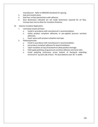
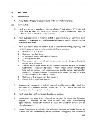
38.4 ADJUSTING
A. Adjust isolators after piping system is at operating weight.
B. Adjust active height of spring isolators.
C. Adjust restraints to permit free movement of equipment within normal mode of
operation.
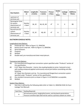
38.5 RESILIENT MOUNTINGS FOR SPECIFIC CLASSIFICATIONS OF MECHANICAL EQUIPMENT:
[Note to A/E: Fill in table with project specific requirements ]
EQUIPMENT LOCATION
ESTIMATED
MINIMUM
ROTATING SPEED
(RPM)
ISOLATION
TYPE
MINIMUM ACTUAL
STATIC DEFLECTION
(INCHES)](https://image.slidesharecdn.com/phplmepspecs-181016075610/85/Technical-Specification-MEP-Works-128-320.jpg)


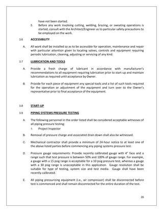
![168
approved.
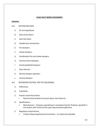
Grab Bar
Basis-of-Design Product: approved
Mounting: Flanges with concealed fasteners.
Material: Stainless steel, 18-guage (1.2 mm) thick.
Finish: Smooth, No. 4 finish (satin).
Outside Diameter: 1-1/4 inches (32 mm).
Configuration and Length: As indicated on BOQ.
Sanitary Napkin vendor dispensers
Sanitary Napkin approved
Sanitary-Napkin Disposal Unit
Basis-of-Design Product: approved
Mounting: [Recessed] [Partition mounted, dual access] .
Door or Cover: Self-closing, disposal-opening cover with tumbler lockset.
Receptacle: Removable.
Material and Finish: [Stainless steel, No. 4 finish]
Seat-Cover Dispenser
Basis-of-Design Product: approved.
Mounting: Surface mounted
Mirror Unit
Tilt Mirror for Handicapped Lavatory:
Basis-of-Design Product: approved.
Size: [As indicated on Drawings].
Mirror:
Basis-of-Design Product: approved.
Size: [As indicated on Drawings]
Diaper-Changing Station
Basis-of-Design Product: approved
Description: Horizontal unit that opens by folding down from stored position and with
child-protection strap.
Engineered to support a minimum of [250-lb (113-kg)] static load when opened.](https://image.slidesharecdn.com/phplmepspecs-181016075610/85/Technical-Specification-MEP-Works-168-320.jpg)
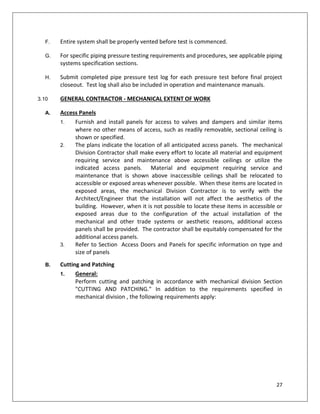
![169
Mounting: [Surface mounted, with unit projecting not more than 4 inches (100 mm)
from wall when closed]
Operation: By pneumatic shock-absorbing mechanism.
Liner Dispenser: Built in.
Shower Curtain Rod
Basis-of-Design Product: approved.
Description: [1-inch (25.4-mm) OD; fabricated from nominal 0.0375-inch- (0.95-mm-)
thick stainless steel
Mounting Flanges: Stainless-steel flanges designed for exposed fasteners
Finish: [No. 4 (satin)] .
Shower Curtain
Basis-of-Design Product: aproved
Size: (specifier select)
Color: As selected from manufacturer's full range.
Grommets: Corrosion resistant at minimum 6 inches (152 mm) o.c. through top hem.
Shower Curtain Hooks: Chrome-plated or stainless-steel, spring wire curtain hooks
with snap fasteners, sized to accommodate specified curtain rod. Provide one
hook per curtain grommet.
Folding Shower Seat
Basis-of-Design Product: approved
Towel Bar
Basis-of-Design Product: approved)
Material and Finish: Stainless steel, No. 4 finish (satin).
2. CUSTODIAL ACCESSORIES
Mop and Broom Holder
Basis-of-Design Product: approved.
Mounting: above service sink, not on wall with faucet.
3. FABRICATION
If applicable to project need.](https://image.slidesharecdn.com/phplmepspecs-181016075610/85/Technical-Specification-MEP-Works-169-320.jpg)
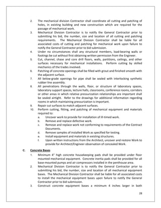
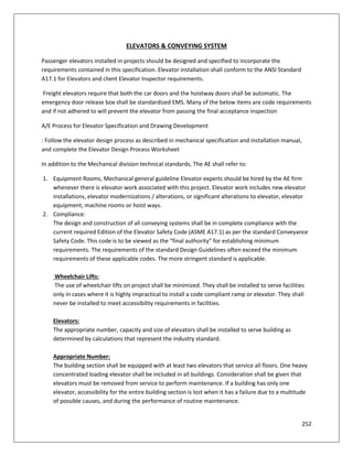
![225
width of corridors serving patients bedrooms in buildings shall be 2400 mm. For detailed
information on
recommendations for buildings and facilities for the physically handicapped, reference may be
made to good
practice [4(27)].
Patient lifts shall also
be provided with enough room for transporting a stretcher trolley.
fire resistant walls. Doors
in fire resistant walls
shall be so installed that these may normally be kept in open position, but will close
automatically. Corridor door
openings in smoke barriers shall be not less than 2000 mm in width. Provision shall also be
made for double swing
single/double leaf type door.](https://image.slidesharecdn.com/phplmepspecs-181016075610/85/Technical-Specification-MEP-Works-225-320.jpg)
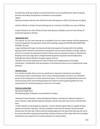
![257
the hall sills shall be fully grouted with a Pre-mixed compound consisting of non-metallic aggregate,
cement, water reducing and plasticizing additives, capable of developing minimum compressive strength
of 4000 psi at 28 days.
[Note to AE: Provide written requirement in masonry section of construction documents. This work is
normally provided by the masonry contractor.]
Grouting Elevator Door Frames:
Entrance frames installed in masonry and concrete walls shall be fully grouted in place. Spreaders shall
be used to prevent elevator doorframes from bowing.
[Note to AE: Provide written requirement in masonry section of construction documents.]
5. No Pipes, Ducts, or Any Other Equipment in Hoistway:
[Note to AE: This is a frequently missed item.]
Only equipment that serves or is associated with the elevator may be installed in any elevator hoist way.
This includes electrical piping, plumbing, drain lines, telecom equipment, ductwork, etc. ASME-A17.1
Section 2.8 6.
Ledges in Hoistways:
Elevator hoist ways are required by code to be substantially flush. Any ledge projecting into the elevator
hoist way over 4 inches is required to have a 75 degree bevel on the top of it. This includes steel I
beams, concrete floor ledges, etc. A17.1 Section 2.1.6.2 7.
Overhead clearance minimum requirements are governed by the elevator code and need to be taken
into consideration with every elevator installation.
8. Hoisting Beam in Overhead:
Hoisting beams adequately sized to safely support the weight of the car and piston shall be installed at
the tops of hydraulic elevator hoist ways. Overhead clearance requirements to the overhead beam shall
still be met as required by code.
9. Fire Rating:
Hoist way shall have all holes and penetrations fire caulked to meet fire rating of hoist way, including the
top of the hoist way, where the ceiling meets the walls. In sprinkled buildings, a sprinkler head should be
located within two feet of the bottom of the hoistway.](https://image.slidesharecdn.com/phplmepspecs-181016075610/85/Technical-Specification-MEP-Works-257-320.jpg)
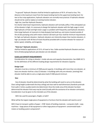
![260
7. Engineering Support:
The original equipment manufacturer shall provide engineering support to any maintaining
contractor so designated by the building owner.
8. Documentation:
Manuals, engineering drawings, circuit diagrams and prints shall be provided with the equipment
at time of delivery. All documentation shall be available for replacement purchase, at reasonable
cost, by any installing or maintaining elevator contractor or persons so designated by the building
owner.
ELEVATOR PIT REQUIREMENTS
Elevator Pit Requirements:
Elevator pits shall be constructed in accordance with and ASMEA17.1, Section 2.2. Hydraulic Jacks:
When possible, coordinate location of geo-technical test bore with elevator jack location to identify
potential sub-grade obstructions or unusually high water tables which may be encountered during
boring for the hydraulic jack. Pitt Ladder: Pit ladders are required in any elevator pit deeper than 35
inches. The ladder shall extend at least 48 inches above the access doorsill level, be within reach of
the access door, and meet the other requirements of ASME A17.1 2.2.4.2
[Note to AE: Provide written requirements and details in the construction documents.]
BASEMENT SET ELECTRIC TRACTION ELEVATORS:
In the event that a variance is granted for the use of a basement set traction elevator, or if cable
type elevators that do not have the machine room located directly over the top of the hoist way are
provided, access to overhead equipment must still be provided. If full body entry is not required
into this space (as defined by the elevator code), only an access door to inspect the governor is
required. If full body entry is required into these spaces, light switch and lighting, electrical
receptacles, metal floor grating, standard railings, access ladder to access door, and additional
overhead clearances are all required. Special attention needs to be given these types of
installations, and the A/E must provide details and specifications in the constructiondocuments.
ACCESS DOOR FOR OVERHEAD MACHINERY SPACES:
(When required) Access doors shall be provided for the inspection of equipment in elevator hoist
way “machinery spaces” as required. The access doors shall be a minimum of 24” x 24” when full
body entry is not required and 29.5” x 29.5” minimum when full body entry is necessary.
Doors shall be self-closing and locking and be keyed the same as the elevator machine room. See
Drawing Overhead Machinery Space Access - Variance.](https://image.slidesharecdn.com/phplmepspecs-181016075610/85/Technical-Specification-MEP-Works-260-320.jpg)
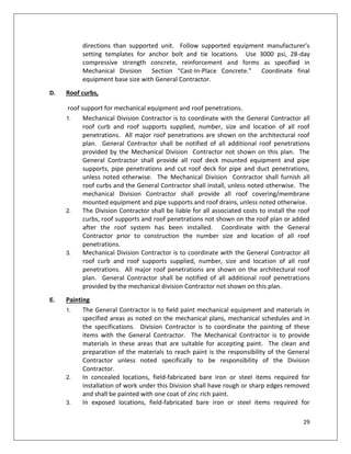
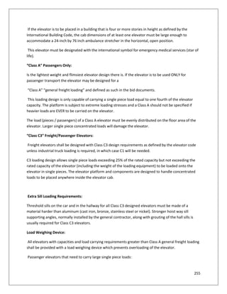
![261
[Note to AE: When an access door is required, the AE must show drawings and location of overhead
access door, and access ladder and platform.]
FULL BODY ENTRANCE:
(When applicable) Full body entrance is usually decided by the location of the governor. If the
elevator governor is located immediately adjacent to a wall where a 24” x 24” door may be
installed, full body entrance is not normally required. Architects should consult with elevator
manufacturers about the location of the governor and provide appropriate detailing for either an
access door or full body access.
ACCESS DOOR ACCESS LADDER:
A code compliant access ladder located to the side of the access door with a standard railing and
platform below the overhead access door shall be provided. Machine Room-less Elevators (MRL):
Minimum MRL Requirements:
1. MRL Overhead Access:
Overhead access shall be provided to all MRL overhead machinery spaces by means of a self-closing,
self-locking access door as per for full body entry as defined by code and as per Design Guidelines to
access such doors, for overhead machinery space access.
3. Lighting and stop switches:
Lighting and stop switches, GFI outlets, etc., shall be provided in the overhead machinery space as
per code for full body entry spaces.
4. Roping:
2:1 roping is the maximum roping that shall be allowed on any MRL unit.
5. T Rails:
Only standard T main and counterweight rails shall be used for MRL units.
6. Car Frame:
Only structural shaped steel members may comprise the construction of the car frame
components.
7. Hoist way Sizing:
MRL hoist way sizing shall be adequate to install Hollister Whitney, Global Tardiff, ThyssenKrupp,
and Motion Control Engineering models of MRL units. This is to allow multiple MRL units to be bid.](https://image.slidesharecdn.com/phplmepspecs-181016075610/85/Technical-Specification-MEP-Works-261-320.jpg)