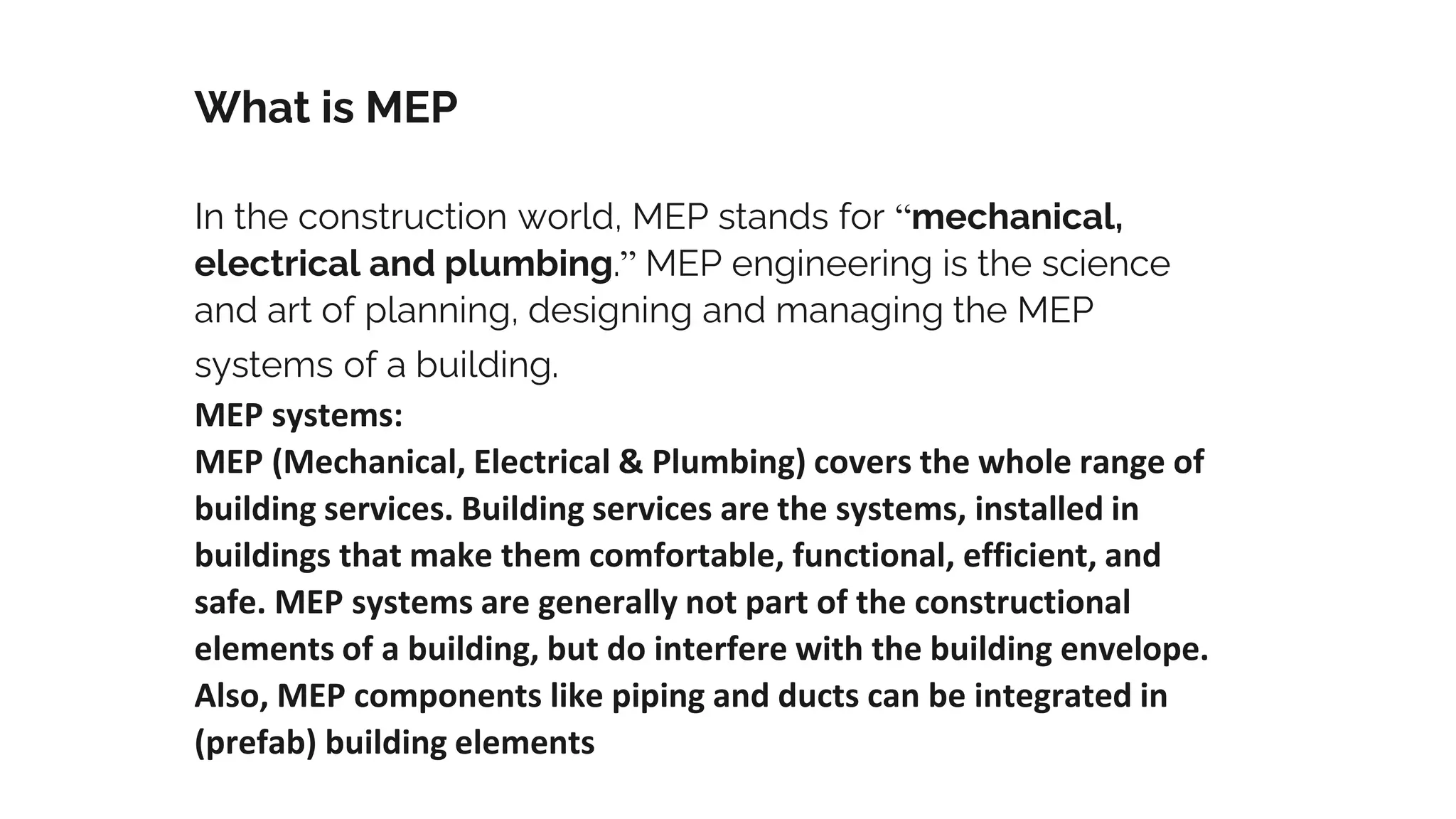
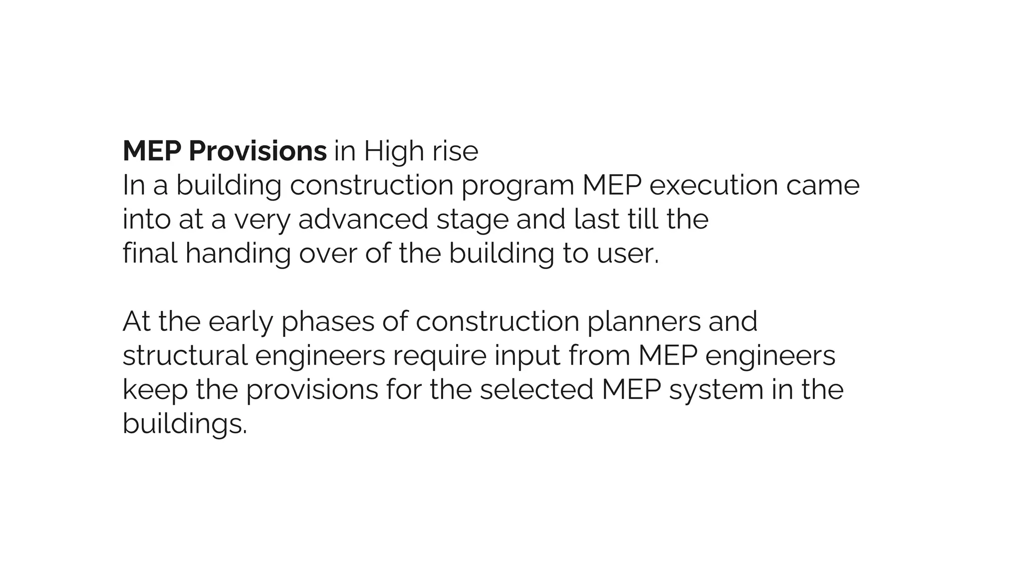
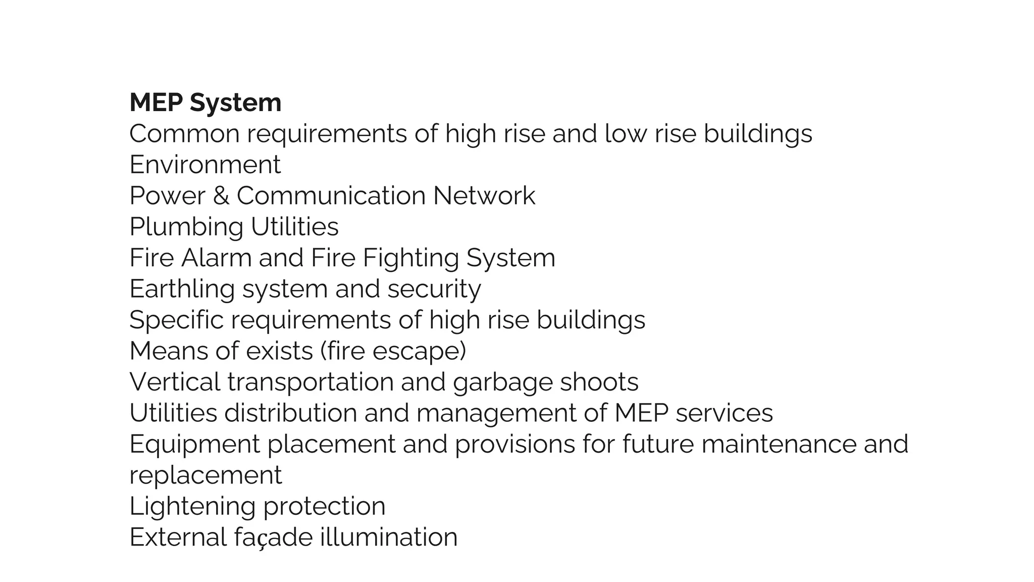
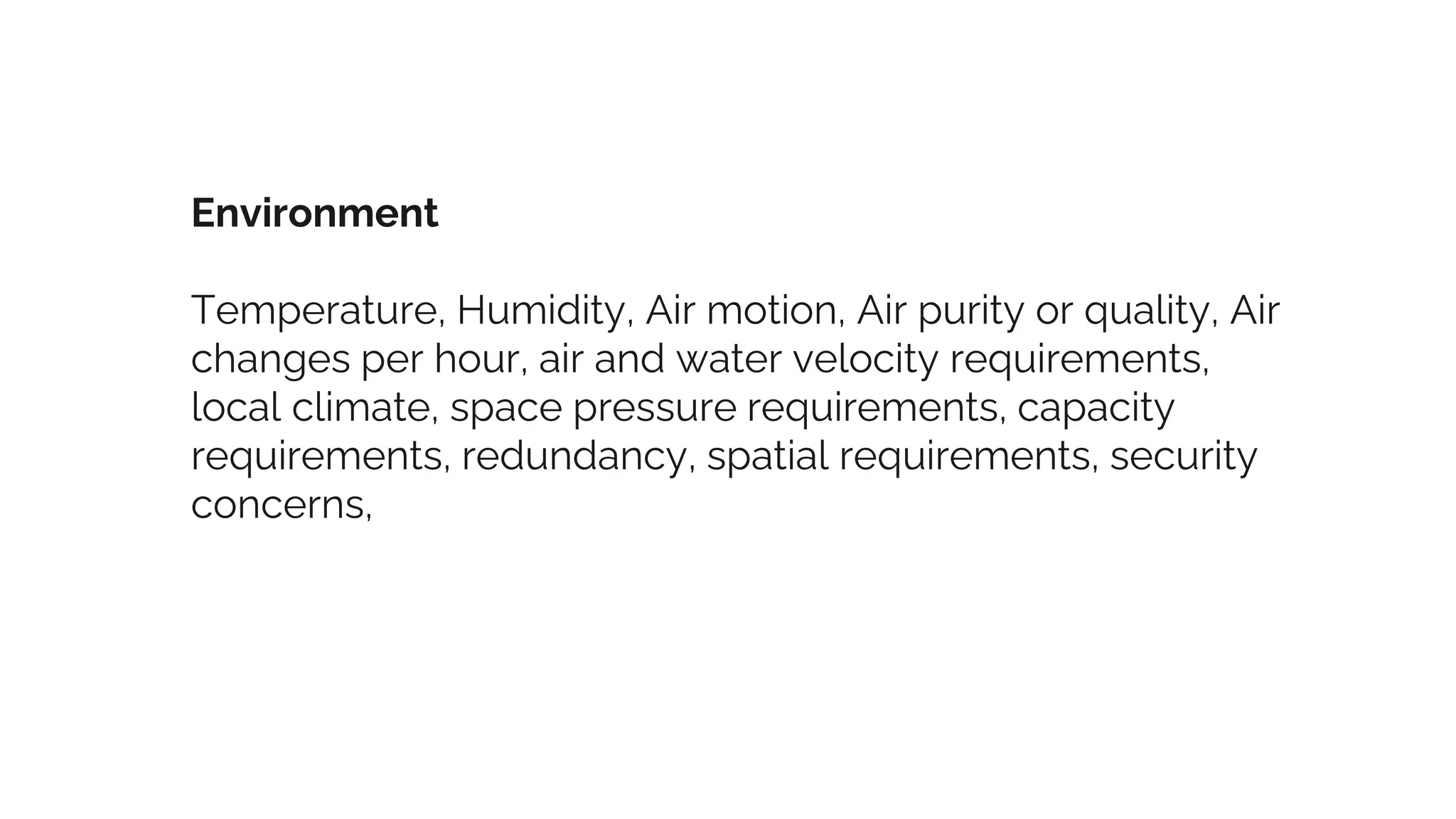
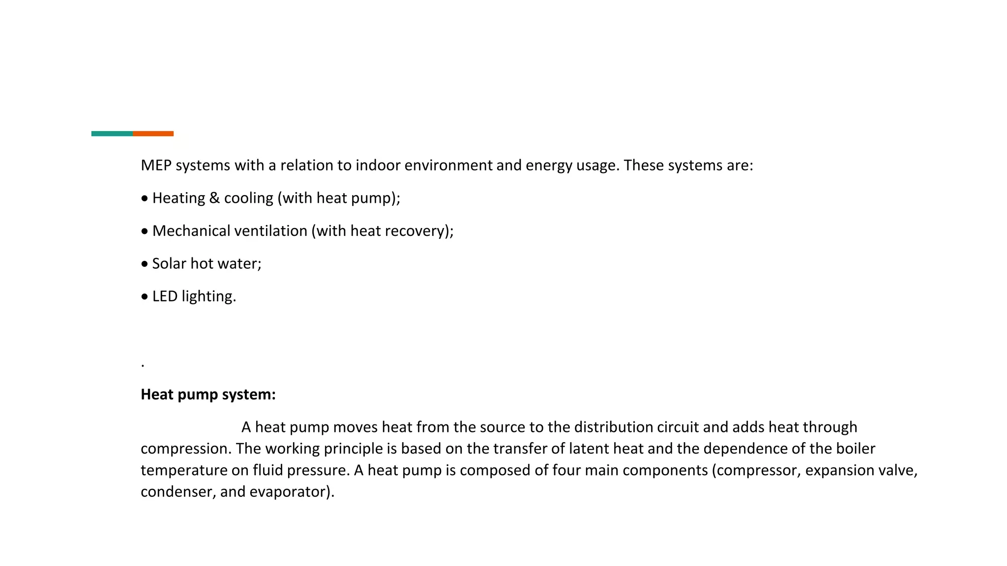
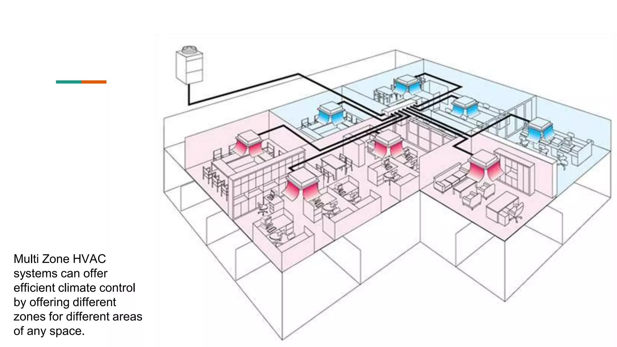
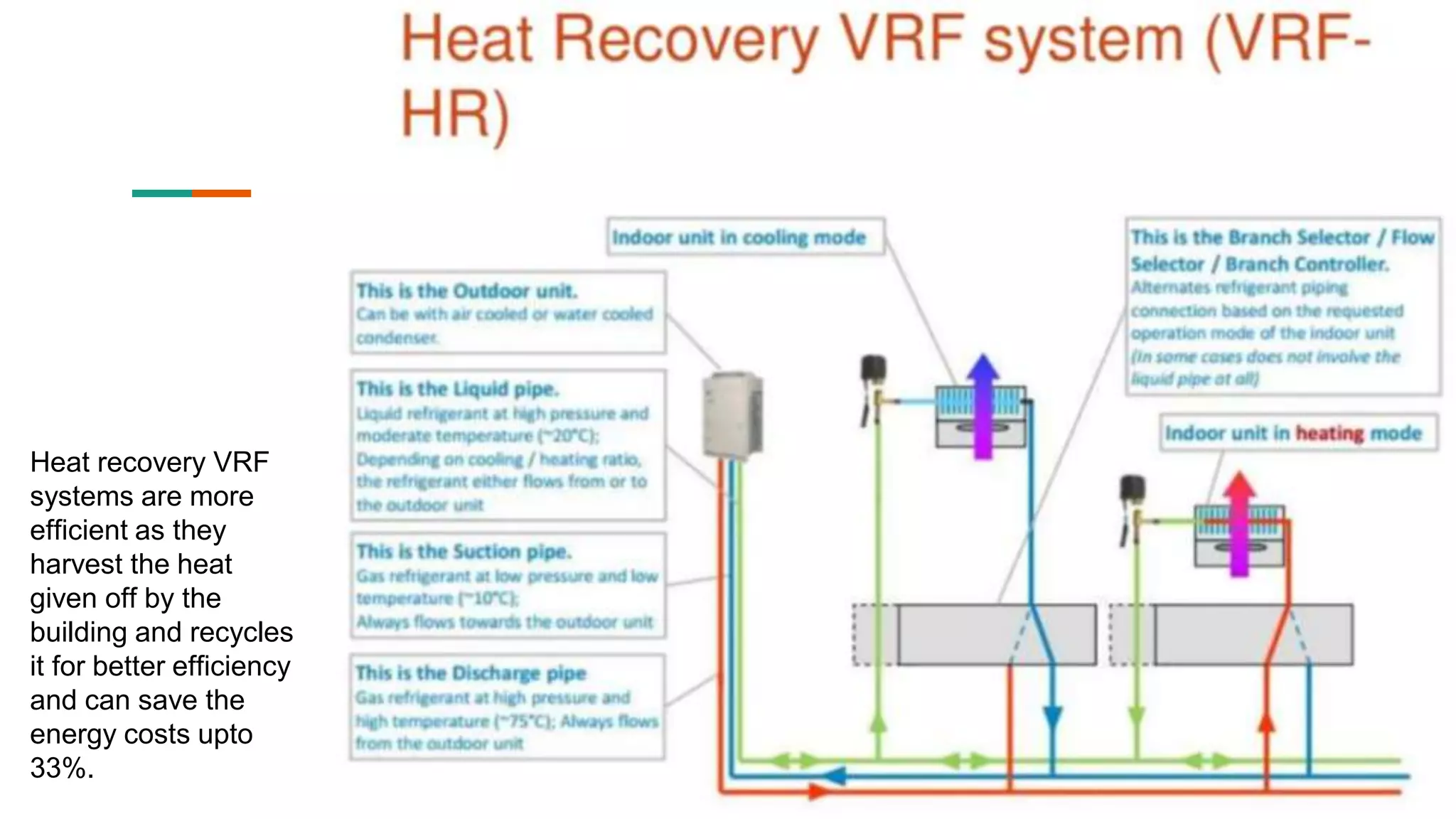
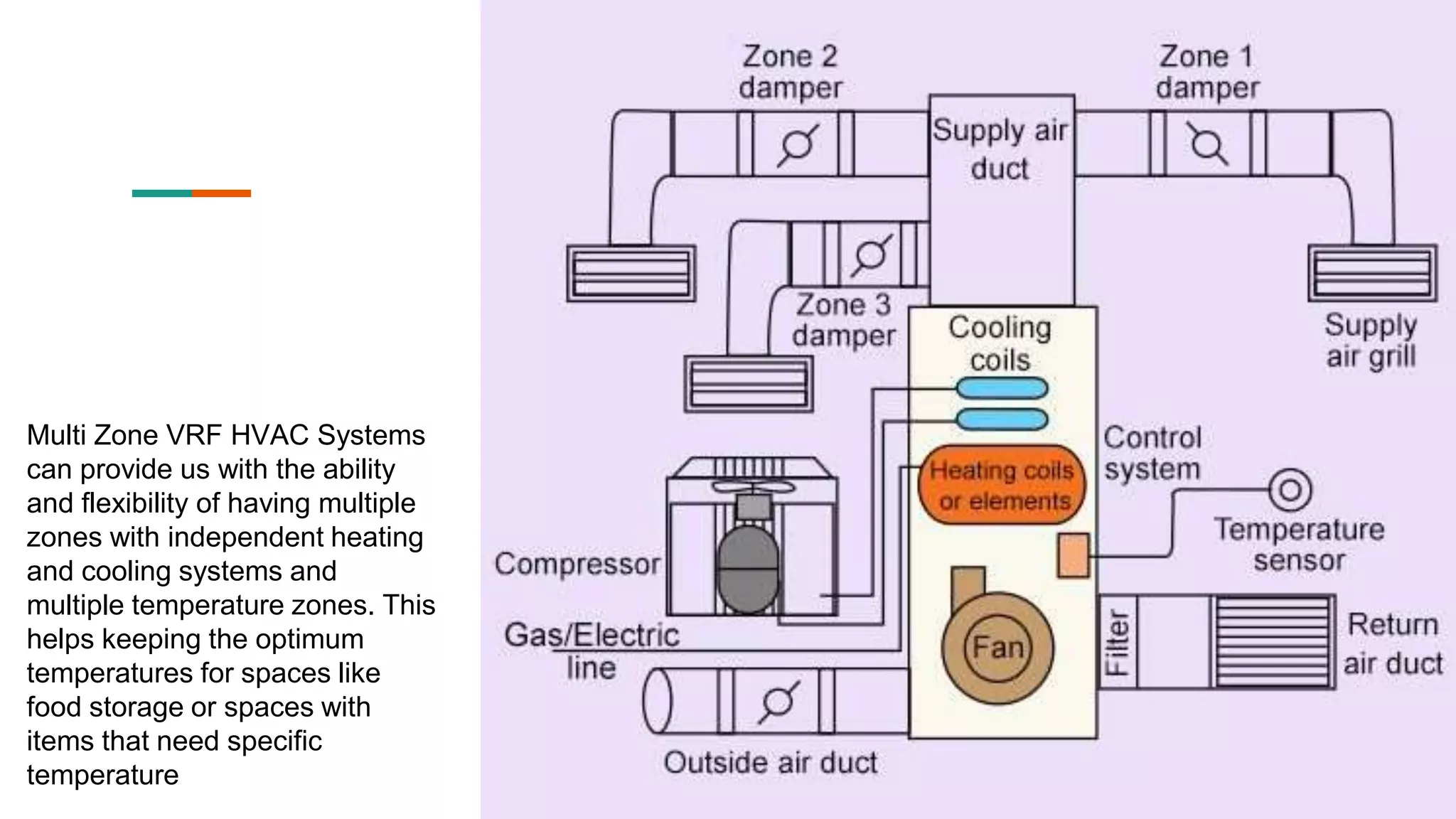
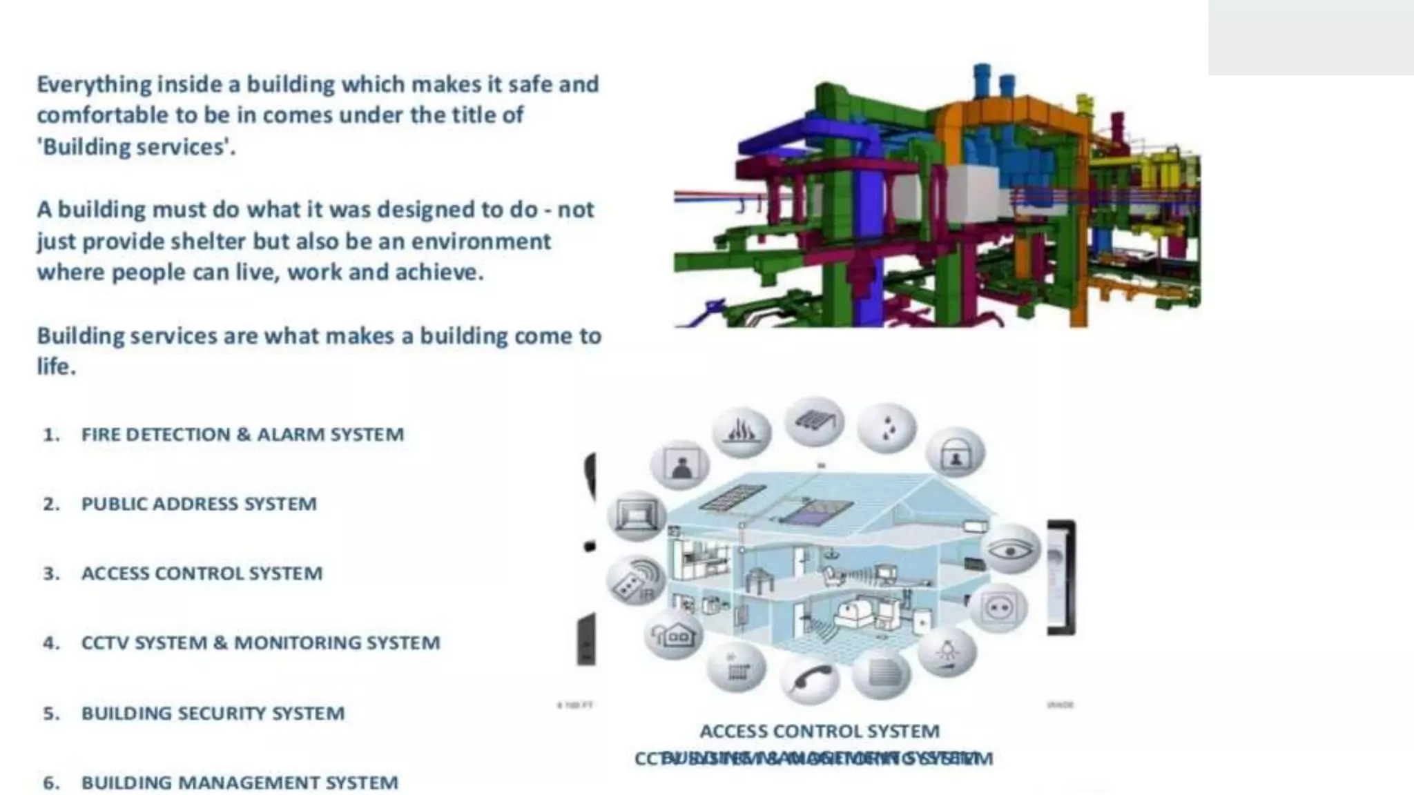
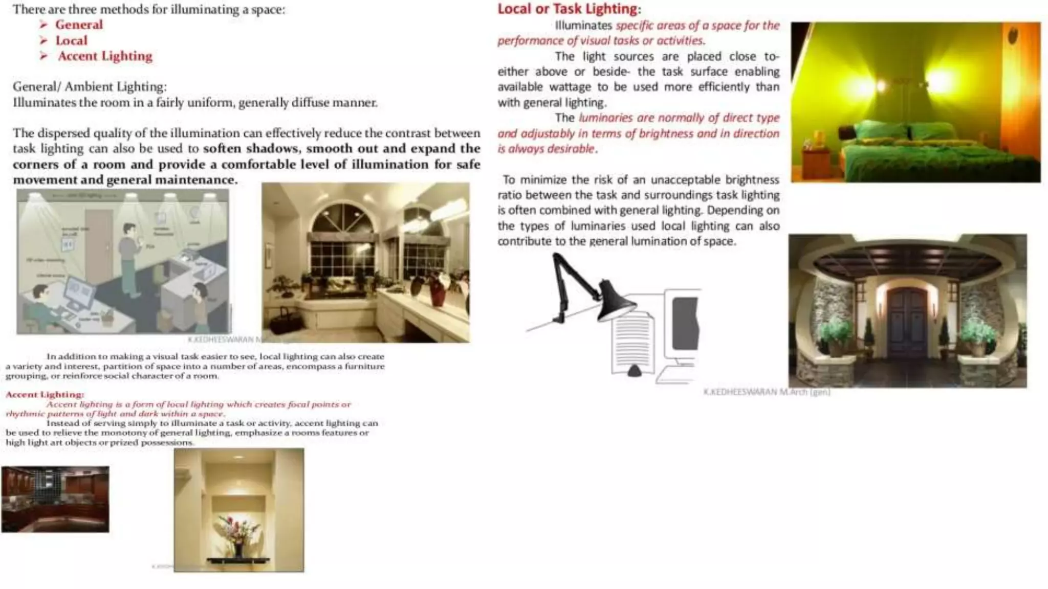
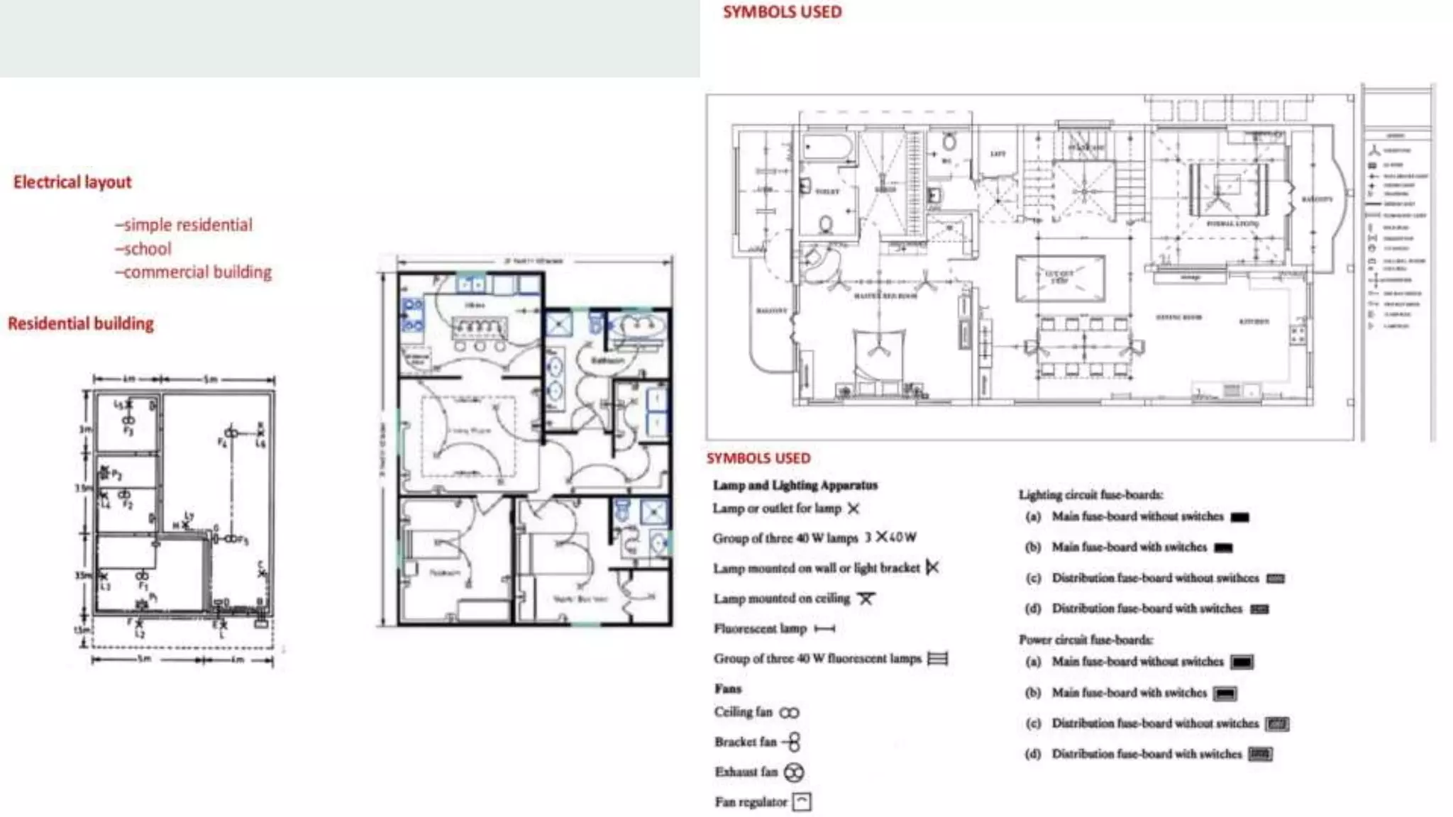
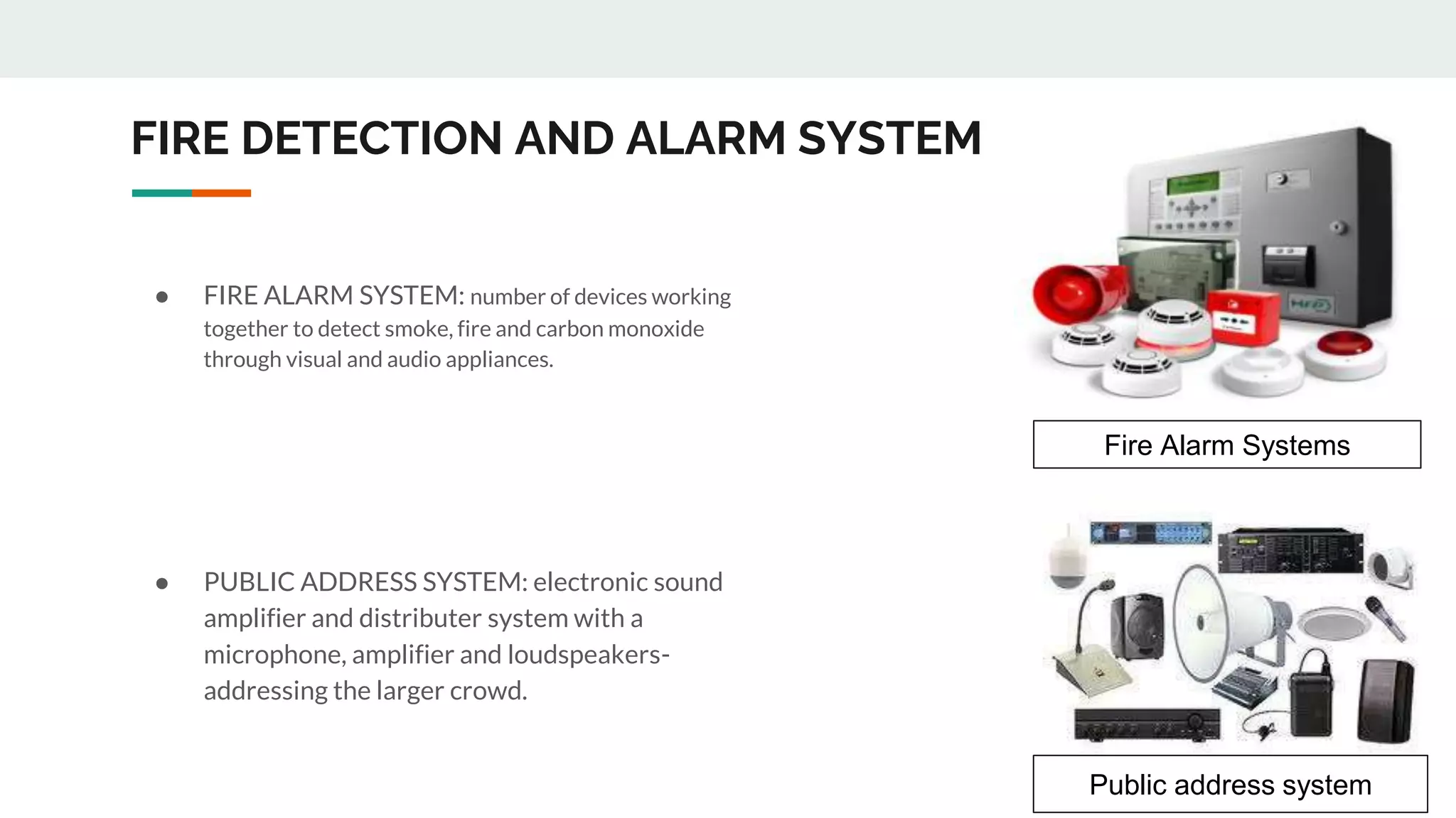
SlideShare a Scribd company logo
MEP
• Fakhar Abbas
Shahrukh
Hasaan H rehman
Ameer Hamza
Farhan Ahmad
Ali Ramzan
Romaisa
Ahmad Tariq
Malik Ahmad
Hannan
PRESENTED BY:
What is MEP
In the construction world, MEP stands for “mechanical,
electrical and plumbing.” MEP engineering is the science
and art of planning, designing and managing the MEP
systems of a building.
MEP systems:
MEP (Mechanical, Electrical & Plumbing) covers the whole range of
building services. Building services are the systems, installed in
buildings that make them comfortable, functional, efficient, and
safe. MEP systems are generally not part of the constructional
elements of a building, but do interfere with the building envelope.
Also, MEP components like piping and ducts can be integrated in
(prefab) building elements
MEP Provisions in High rise
In a building construction program MEP execution came
into at a very advanced stage and last till the
final handing over of the building to user.
At the early phases of construction planners and
structural engineers require input from MEP engineers
keep the provisions for the selected MEP system in the
buildings.
MEP System
Common requirements of high rise and low rise buildings
Environment
Power & Communication Network
Plumbing Utilities
Fire Alarm and Fire Fighting System
Earthling system and security
Specific requirements of high rise buildings
Means of exists (fire escape)
Vertical transportation and garbage shoots
Utilities distribution and management of MEP services
Equipment placement and provisions for future maintenance and
replacement
Lightening protection
External façade illumination
Environment
Temperature, Humidity, Air motion, Air purity or quality, Air
changes per hour, air and water velocity requirements,
local climate, space pressure requirements, capacity
requirements, redundancy, spatial requirements, security
concerns,
Plumbing
Water Supply distribution booster system v/s gravity based tank
supply.
Provisions of pressure reducers and Isolation valves
Filling arrangement for overhead tank, provision of buffer tank at
intermediate floor.
Balcony/trace drain, roof drains
Drainage risers to be located strategically with access for regular
maintenance
Transfer floor v/s drainage offset
Centralized drinking water system
Fire Fighting
Fire zoning and compartments
Sprinkler system with zone control valves
Fire hose cabinets for occupants
Dry Risers/Fire hose cabinets for fire fighters
Centralized Fire Alarm system in fire rated conduits
Gas based fire fighting system for protection of big ticket
equipment
NFPA/BS Codes must be followed
Earthing / Electrical System
System earthling network to be provided at each locations
Body earthling for central equipment
NEC/BS codes must be followed
Security
CCTV
electronic access to various areas to be provided
Parking management system
MEP systems with a relation to indoor environment and energy usage. These systems are:
 Heating & cooling (with heat pump);
 Mechanical ventilation (with heat recovery);
 Solar hot water;
 LED lighting.
.
Heat pump system:
A heat pump moves heat from the source to the distribution circuit and adds heat through
compression. The working principle is based on the transfer of latent heat and the dependence of the boiler
temperature on fluid pressure. A heat pump is composed of four main components (compressor, expansion valve,
condenser, and evaporator).
Hot source & Cold source (ATES-Aquifer Thermal Energy
Storage):
An aquifer is a permeable layer of sand containing
water. The layer is vertically separated by impermeable layers
that typically consist of clay. The hot and cold source can be
located at different depth in different aquifers or in the same
layer with a certain horizontal distance in order to prevent short-
circuiting. A source consists of a well drilled into the ground,
typically to a depth of 30 m to 150 m. Where a perforated tube
injects or extracts the ground water from the aquifer making use
of a pressure difference inside the well. For this purpose, the well
is closed off at the top. In the summer period, cold ground water
is extracted from the aquifer and used to cool the building. The
heat that is extracted from the building it is transferred to the
water and inserted in the hot source. During heating season, the
hot ground water is extracted from the hot source, when the
heat is transferred to the building the cooled water is in turn
injected in the cold source.
Gas fired Boiler:
A gas-fired boiler is often used to
satisfy the peak heating demand. When the heat
pump has to satisfy the peak demand, it will
become very large. The result of a large heat pump
is a decrease in efficiency at periods of low demand
and a high initial investment. The gas-fired boiler
only operates when the heat pump operates at full
capacity. It is important that the return
temperature to the gas fired boiler is sufficiently
low to allow condensation of the exhaust gasses.
Without condensation, the efficiency of the boiler is
strongly reduced. This applies to the distribution
system but also to the temperature regulation
system, mechanisms where heated water is mixed
with the return water should be prevented.
Hydraulic system optimization:
This hydronic system optimization tool returns the optimal sizes and settings of the hydronic
system, such as pipes, pumps and valves but also test the control strategies of the installation. These settings
are to be stored in the BIM and serve as self-instruction and reference for self-inspection for the on-site worker
who administers the settings to the component
Introduction:
Ventilation is the intentional introduction of outside air into
a space or room. It is mainly used to control indoor air quality by diluting
and displacing indoor pollutants, such as CO2. It can be categorized as
either mechanical ventilation, or natural ventilation. Mechanical ventilation
uses fans to drive the flow of outside air into a building and natural
ventilation is the intentional passive flow of outside air into a building
through planned openings (such as louvers, doors, and windows). Natural
ventilation does not require mechanical systems to move outside air, it
relies entirely on passive physical phenomena, such as wind pressure, or
the stack effect.
There are four recognized ventilation systems that vary from
completely natural ventilation to mixed ventilation and mechanical
ventilation. These systems are often indicated with the letters A to D.
 System A: natural air exhaust and air supply;
 System B: natural air exhaust and mechanical air supply (rare);
 System C: natural air supply and mechanical air exhaust;
 System D: mechanical air exhaust and mechanical air supply
(balanced ventilation).
Ventilation system
System A: natural air exhaust and air supply:
System A is an installation that does not contain any electrical driven
components. Fresh air is supplied naturally through vents built in the
windows. The air intake of these vents can be adjusted manually.
Polluted air is expelled via vertical ducts in toilets, bathroom and/or
kitchen or also through the vents in the windows. Air flow is caused by
pressure differences between the building and its surrounding.
System B: natural air exhaust and mechanical air supply (rare);
A controlled supply of fresh outside air is forced through the
building using a fan and the outdoor air is transported into the
building by ducts. The air exhaust takes place on a natural way
by ventilation openings, windows, or shafts because of the forced
overpressure in the building. An air filter can be used to clean the
incoming air. Because of the mechanically produced over
pressure in the building, the system is less dependent on the
weather conditions than a completely natural ventilation system.
System C: natural air supply and mechanical air exhaust;
The mechanical air exhaust system creates an under-
pressure in the building, through which this system is also, like
system B, less dependent to weather conditions than completely
natural ventilation. The mechanical air exhaust creates a
pressure difference over the ventilation openings, so air is suck
in. A controllable exhaust fan controls the ventilation capacity. In
residential buildings exhaust takes place from at least the
kitchen, the bathroom, and the toilet. In non-residential buildings
suction mostly takes place from the corridor. Exhaust air ducts
are needed.
System D: mechanical air exhaust and mechanical air supply
(balanced ventilation).
In this system, the supply air and the exhaust air are transported
mechanically. In comparison with the other three systems the
advantages of balanced ventilation are the possibility of
extracting heat from the exhaust air and use it to preheat the
fresh air supply (heat recovery). Like system B it is possible to
use preheating, pre-cooling, humidifying and/or an air filter.
By controlling the ventilators, it is possible to control the ventilation capacity of the
system. For proper functioning of the system the building must be sufficiently airtight.
Air Handling Units (AHU):
Circulation, filtration, heating,
cooling, heat recovery, humidifying,
dehumidifying and mixing of air. The more
functions an air handling unit has, the greater
its influence is on the energy performance and
indoor environmental quality of a building. Air
handlers usually connect to a ductwork
ventilation system that distributes the
conditioned air through the building and
returns it to the air handling unit. Sometimes
air handling units supply and return air directly
to and from the space served without
ductwork, like for example in a packaged
rooftop unit.
Fans:
A fan is a rotary bladed machine, used to
maintain a continuous flow of air. The fan is the
heart of the air handling unit and a significant
energy user in a building. Commissioning and re-
commissioning fans and drives is a key factor for
ensuring that a building’s efficiency goals are met
over the life of the building.
Filters:
All ventilation systems employ a filtration
system. These requirements are driven by the need
to maintain indoor air quality (IAQ), protect the
occupants from airborne hazards and
contaminants, or maintain cleanliness in an
occupied zone or production area.
Heat Recovery Element (HRE):
A heat recovery device of many types is used in an air handling system
between supply and return airstreams for energy savings. The amount of energy that is
transferred by the heat exchanger is known as its ‘effectiveness’ or ‘efficiency’. If a heat
exchanger were to be able to transfer the entire energy from one medium to another, it
would be rated at 100% efficiency.
Humidifiers: Active humidification systems are complex, expensive to operate,
and maintenance intensive, so these systems are seldom employed unless they
are essential. Eliminating unnecessary humidification systems can yield
substantial benefits. Active humidification is an energy intensive process that can
also create moisture problems if not properly designed, installed, and
implemented. Thus, the commissioning of these systems can be critical to their
success. Methods for humidification include:
 Direct or indirect steam injection
 Evaporative approaches
 Compressed air driven
 Ultrasonic
 Air washers
 Sprayed coils
Ventilation Units:
A ‘ventilation unit’ (VU) is an electricity driven appliance
equipped with at least one impeller, one motor and a casing and
intended to replace utilized air by outdoor air in a building or a part of
a building.
There are two different types of VUs:
 Unidirectional ventilation units (UVUs):
Ventilation units producing an air flow in one direction only,
either from indoors to outdoors (exhaust) or from outdoors to indoors
(supply), where the mechanically produced air flow is balanced by
natural air supply or exhaust;
 Bidirectional ventilation units (BVU):
Ventilation units producing an air flow between indoors and
outdoors and are equipped with both exhaust and supply fans.
Duct Systems:
The distribution system (ducts) provides the
path between the outer air, the air handling system and the
terminal equipment that distributes the conditioned air. While
relatively passive, it can often account for a significant portion
of the system’s energy consumption due to the static pressure
requirement it imposes on the fan. Ducts can be constructed
from plate material or plastic on-site, but can also be
integrated in (prefab) construction elements.
Silencers:
A silencer is used for the noise absorption generated
by the ventilation units and spreading via the air ducts of the
ventilation system. In order to select the right silencer, the
design of the ventilation system and its components must be
known. Also, the ‘rule of thumb’ is used too often, causing
noise problems in the building.
Dampers and valves:
A damper is a valve or plate that stops or regulates the flow of
air inside a duct, air handling unit or other air handling equipment. A
damper can be used to regulate air flow rate for room-by-room
temperature and climate control. Its operation can be manual or
automatic. Manual dampers are turned by a handle on the outside of
a duct. Automatic dampers are used to regulate airflow constantly and
are operated by electric or pneumatic motors.
Air Terminal Devices (ATDs):
Components of the installation which are designed for
the purpose of achieving the predetermined movement of air into or
from the treated space. The terminal equipment associated with an
HVAC system provides the interface between the HVAC process that
conditions the air and the occupants and processes occurring in the
space.
Control system:
The control system or building automation system is
the operator of the ventilation system. It operates the fan,
heating/cooling elements, humidifiers, dampers, valves, and terminal
equipment. The most common functions are the control of space
temperature and indoor air quality and thus cannot be seen
completely separate from the heating/cooling system. In addition to
these functions, ventilation specific function like humidity control and
filtration systems can be employed.
Solar hot water system:
Solar thermal systems are one of the main current
installed HVAC/MEP systems in building with the aim of generation
Domestic Hot Water (DHW). It is the main renewable sources for
generation of this energy. Solar thermal systems use free energy from
the sun (solar radiation) to produce useful heat in a first instance.
Solar collectors:
By nature, the collectors are the most visible of all
solar thermal components – they are typically mounted
on the roof of a building, but can also be placed on the
façade, on balconies or mounted on ground structures. All
collector types have in common that solar irradiation is
absorbed by a dark – often black or dark-blue – surface,
which heats up and from which the heat is transferred
directly or indirectly.
Pump:
For pumped systems, the use of electricity for
pumps should be kept as low as possible, and therefore
over dimensioning of the power of the pump should be
avoided.
Heat exchanger:
For the transfer of the heat
gained from the sun to the domestic hot
water, a heat exchanger is required in
twin circuit systems. We can
differentiate between internal and
external heat exchangers.
LED Lighting Systems:
Lighting systems are
installed to provide a building with
artificial lighting when natural
lighting is insufficient or unavailable.
This can be because a space has no
windows, insufficient windows, or
when the space is to be used at
times when there is insufficient
daylight. Lighting can be provided by
different types of systems, currently
most office buildings are lit using
fluorescent lighting.
• As an alternative to the problematic older high rise HVAC choices, builders and developers are looking to a newer
technology called Variable Refrigerant Flow, or VRF systems.
• VRF has been the high rise HVAC system of choice in Japan and Europe for many years. Yet VRF systems have only
been introduced in the US within the past decade or so, and have been quickly gaining popularity due to the
efficiencies of the system and the superior comfort levels they can provide.
• The VRF system is consists of a large condensing unit that feeds numerous smaller air handlers throughout the
space. It’s air-cooled, which eliminates both the danger of water leaks and the need for chemical treatments to
prevent the growth of bacteria. Here are some of the reasons why more builders are choosing the VRF system for
high rise residential construction projects.
Advantages of VRF systems for high rise buildings
CUSTOM COMFORT: The system is capable of varying the amount of refrigerant being piped to individual air handlers
(hence the name), which gives VRF technology an unequalled ability to provide customized heating and cooling via
multiple zones within a space. This customization also helps with the issues of varying demand between upper and
lower floors.
ENERGY EFFICIENCY: The technology used by the VRF system minimizes energy consumption. The system is also
designed to reuse heat given off in the condensing process to provide heat in other areas of the space, so it can be
used for supplemental heating.
QUIET OPERATION: The use of smaller air handlers, and lack of ducts for many installations, means quiet for the
homeowner.
LESS SPACE REQUIREMENTS: Those smaller air handlers also translate to less indoor space required to house the
units.
MORE DEPENDABLE: Since the compressor runs at a lower capacity in a VRF system, there is less wear and tear, which
results in fewer breakdowns
VRF SYSTEMS: THE HIGH RISE HVAC SYSTEM OF CHOICE
Heat recovery VRF
systems are more
efficient as they
harvest the heat
given off by the
building and recycles
it for better efficiency
and can save the
energy costs upto
33%.
• As an alternative to the problematic older high rise HVAC choices, builders and developers are looking to a newer
technology called Variable Refrigerant Flow, or VRF systems.
• VRF has been the high rise HVAC system of choice in Japan and Europe for many years. Yet VRF systems have only
been introduced in the US within the past decade or so, and have been quickly gaining popularity due to the
efficiencies of the system and the superior comfort levels they can provide.
• The VRF system is consists of a large condensing unit that feeds numerous smaller air handlers throughout the
space. It’s air-cooled, which eliminates both the danger of water leaks and the need for chemical treatments to
prevent the growth of bacteria. Here are some of the reasons why more builders are choosing the VRF system for
high rise residential construction projects.
Advantages of VRF systems for high rise buildings
CUSTOM COMFORT: The system is capable of varying the amount of refrigerant being piped to individual air handlers
(hence the name), which gives VRF technology an unequalled ability to provide customized heating and cooling via
multiple zones within a space. This customization also helps with the issues of varying demand between upper and
lower floors.
ENERGY EFFICIENCY: The technology used by the VRF system minimizes energy consumption. The system is also
designed to reuse heat given off in the condensing process to provide heat in other areas of the space, so it can be
used for supplemental heating.
QUIET OPERATION: The use of smaller air handlers, and lack of ducts for many installations, means quiet for the
homeowner.
LESS SPACE REQUIREMENTS: Those smaller air handlers also translate to less indoor space required to house the
units.
MORE DEPENDABLE: Since the compressor runs at a lower capacity in a VRF system, there is less wear and tear, which
results in fewer breakdowns
VRF SYSTEMS: THE HIGH RISE HVAC SYSTEM OF CHOICE
Multi Zone HVAC
systems can offer
efficient climate control
by offering different
zones for different areas
of any space.
• As an alternative to the problematic older high rise HVAC choices, builders and developers are looking to a newer
technology called Variable Refrigerant Flow, or VRF systems.
• VRF has been the high rise HVAC system of choice in Japan and Europe for many years. Yet VRF systems have only
been introduced in the US within the past decade or so, and have been quickly gaining popularity due to the
efficiencies of the system and the superior comfort levels they can provide.
• The VRF system is consists of a large condensing unit that feeds numerous smaller air handlers throughout the
space. It’s air-cooled, which eliminates both the danger of water leaks and the need for chemical treatments to
prevent the growth of bacteria. Here are some of the reasons why more builders are choosing the VRF system for
high rise residential construction projects.
Advantages of VRF systems for high rise buildings
CUSTOM COMFORT: The system is capable of varying the amount of refrigerant being piped to individual air handlers
(hence the name), which gives VRF technology an unequalled ability to provide customized heating and cooling via
multiple zones within a space. This customization also helps with the issues of varying demand between upper and
lower floors.
ENERGY EFFICIENCY: The technology used by the VRF system minimizes energy consumption. The system is also
designed to reuse heat given off in the condensing process to provide heat in other areas of the space, so it can be
used for supplemental heating.
QUIET OPERATION: The use of smaller air handlers, and lack of ducts for many installations, means quiet for the
homeowner.
LESS SPACE REQUIREMENTS: Those smaller air handlers also translate to less indoor space required to house the
units.
MORE DEPENDABLE: Since the compressor runs at a lower capacity in a VRF system, there is less wear and tear, which
results in fewer breakdowns
VRF SYSTEMS: THE HIGH RISE HVAC SYSTEM OF CHOICE
Heat recovery VRF
systems are more
efficient as they
harvest the heat
given off by the
building and recycles
it for better efficiency
and can save the
energy costs upto
33%.
Multi Zone VRF HVAC Systems
can provide us with the ability
and flexibility of having multiple
zones with independent heating
and cooling systems and
multiple temperature zones. This
helps keeping the optimum
temperatures for spaces like
food storage or spaces with
items that need specific
temperature
ELECTRICAL
MEP
LIGHTNING
LIGHTINING
LIGHTINING
LIGHTINING
FIRE DETECTION AND ALARM SYSTEM
● FIRE ALARM SYSTEM: number of devices working
together to detect smoke, fire and carbon monoxide
through visual and audio appliances.
● PUBLIC ADDRESS SYSTEM: electronic sound
amplifier and distributer system with a
microphone, amplifier and loudspeakers-
addressing the larger crowd.
Fire Alarm Systems
Public address system
SMART DETECTORS
MANUAL BREAK
GLASS OPERATOR
1. Conventional Fire Alarm Systems
In a Conventional Fire Alarm System, physical cabling
is used to interconnect several call points and
detectors, the signals from which are wired back to the
main control unit.
Call points and detectors are arranged in “Zones” to
simplify locating the cause of the alarm, this is
important for both the fire brigade and general building
management.
Each zone is indicated at the Fire Alarm Control Panel
either with an indicator lamp, a text display or in some
cases both.
2. Addressable Fire Alarm Systems
The detection circuit is wired as a loop.
It is common for the loop to be fitted with Loop
Isolation Modules so that the loop is sectioned
in order to ensure that a short circuit or single
fault will only cause the loss of a small part of
the system; allowing the rest of the system to
function normally
3. Intelligent Fire Alarm Systems
Intelligent Fire Alarm system, each detector
effectively incorporates its own computer
which evaluates the environment around it
and communicates to the Control Panel
whether there is a fire, fault or the detector
head needs cleaning.
Intelligent Fire Alarm Systems are available in
2, 4, and 8 loop versions which means large
premises can be monitored from one single
panel.
4. Wireless Fire Alarm Systems
Wireless Fire Alarm System.
These are an effective alternative to
traditional wired fire alarm systems for all
applications. They utilize secure, license-
free radio communications to interconnect
the sensors and devices with the
controllers.
SCHEMATIC- ACCESS CONTROL ROOM
CCTV AND SECURITY SYSTEMS
● An analogue camera is a
traditional camera used in CCTV
systems. It sends video over cable
to VCRs or DVRs.
● IP cameras are all digital
cameras that can send signals
over cable to be stored in the
network. Many security camera
systems today are hybrid systems
incorporating both analogue and
digital components.
Building Management system
BMS, connects all the equipment into centralized
mannar. It controls, monitors and optimizes the
MEP equipments using hardware and software
components.
Microprocessor
based controllers,
connecting directly
to these equipments
Data received by the system translate into graphical user interface
PLUMBING
INTRODUCTION
Sewage:
•Also known as waste water
•The liquid waste obtained from a community.
•Includes discharges from latrines, urinals, & stables
•Discharges from industry & rainfall are also included
Types of Sewage:
a. Sanitary Sewage
b. Industrial Sewage
c. Combined Sewage
a. Sanitary Sewage:
• Also known as Domestics Sewage
• The foul discharges from residential &
commercial area
• It mainly includes discharges from
latrines, urinals, laundry etc
b. Industrial Sewage:
• The foul discharges from
industries
• It includes discharges produced
during the manufacturing of goods
c. Combined Sewage:
• Combination of Sanitary sewage &
Storm water
• Storm water is rain & snow melt that
runs off surfaces such as rooftops,
paved streets, highways & parking lots.
Sewerage System:
Sewerage:
• Sewage is produced everyday in towns & cities.
• Accumulation of sewage increases if not conveyed regularly
• Sewage has to be removed as early as possible.
• If not removed, it will cause insanitary condition
• The network of collecting & conveying sewage by water carriage system through under
ground pipes sewers is known as Sewerage.
• Components of sewerage system are :
a) Drain b) Manhole c) Pumping station d) Sewer
Drain:
Is a plumbing fixture that
provides an exit-point for waste
water or water that is to be re-
circulated
The opening or hole through which a
man can enter the sewer line or other
closed structure for inspection and
cleaning
Includes pumps &equipments for
pumping fluids.
Supplies water to remove sewage from
processing site
Man hole: Pumping Station:
Sewer:
• Are the underground conduits or drains
• Used for carrying the sewage
• The most common types of sewer are:
I. Sanitary Sewer :
• Is a underground carriage system.
• Used for transporting sewage from houses and commercial
buildings
• Sanitary sewers serving industrial areas also carry Industrial
sewage.
• Sanitary sewage is collected with the help of sanitary sewer
line
• The sanitary sewer is attached to a main sewer.
• The main sewer runs directly to the sewage treatment
plant.
II. Storm Sewer:
• A storm sewer collects storm water with the help of gutter &
catch basin
• Gutter allow the storm water to drain from the street directly
into the storm sewer.
Sewer:
III. Combined Sewer:
• Type of sewer system
• Collects sanitary sewage & storm water run off in a single pipe system.
• Can cause serious water pollution problems due to combined sewer overflows
• Caused by large variations in flow between dry and wet weather.
• This type of sewer design is no longer used in building new communities.
Principles Of Sanitation:
Following are the principles for better
living condition:
 Waste materials like sewage should be
removed as early as possible
 Sewage after collection should be
treated within four hours.
 Effluent should be disposed of
immediately
 Building should be damp proof
Water supply should be regular &
sufficient so that the lavatories may be
done properly
Features Of Sewerage System:
A. Collection & Conveyance :
• Sewage is collected & conveyed through the system of pipe lines
or sewers
• The system of sewers is called sewerage or sewerage system
• Where sewerage system is not provided, sewage is collected in
septic or imhoff tank
Main features of sewerage system are :
A. Collection B. Conveyance C. Treatment D. Disposal
C. Sewage Treatment:
• Is a process of removing contaminants from sewage
• Objective is to produce an environmentally safe treated effluent
and sludge suitable for disposal or reuse
• Discharge to the environment must be accomplished without
transmitting diseases or endangering aquatic organisms,
Sewage Treatment :
There are 2 types of treatment system:
I. Septic & Imhoff Treatment System II. Waste Water Treatment Plant (WWTP)
I. A) Septic System:
• Consists of two major parts, the septic tank &
drain field
• The septic tank separates the sewage into three
components : Sludge(solid waste), Scum
(floatables) & Effluent (grey -water)
• Working Of Septic Tank:
1. Sewage enters via the inlet pipe
2. Gravity pulls the solids to the base.
3. Scum layer is formed on the surface due to anaerobic
biological action.
4. Grey water leaves through the outlet pipe.
5. The effluent flows into a distribution box which then
distributes the effluent equally among the trenches in
the drain field.
Sewage Treatment :
Working Of Drain field:
1. The final treatment takes place in drain field.
2. Effluent trickles out of the pipes, through the gravel
layer and passes into the soil
3. The soil filters the wastewater as it passes through
the pore spaces
4. The soil microbes deactivates the disease germs that
remain in the effluent
5. Eventually treated water enters the groundwater
6. These processes work best where the soil is dry,
permeable, and contains plenty of oxygen below
the drain field.
Sewage Treatment :
I. B) Imhoff Treatment System:
• Is a 2 storied sludge digestion tank
• Invented by German scientist Mr. Karl Imhoff
• Working Of Imhoff Tank:
1. Sewage enters via the inlet pipe
2. Settling of solids occurs in the upper compartment.
3. Effluent leaves through the outlet pipe.
4. Sludge falls through the slot to the digestion tank.
5. Anaerobic bacteria decomposes the organic matter.
6. Digestion process generates biogas
7. Biogas escapes through gas vent
8. Digested sludge is removed by the sludge removal
pipe
Sewage Treatment Process:
Primary Treatment:
• It is a physical process.
• Also known as sedimentation stage
• Sewage flow is slowed down
• Suspended solids settles to the bottom by gravity
• The material that settles is called sludge or bio solids
• Sludge is pumped to the sludge digestion tank.
• Effluent is pumped to the trickling filter or aeration tank for secondary treatment.
Features Of Sewerage System:
Sewage Disposal :
• Is an action or a process of throwing away or getting rid
of sewage.
• Purpose of Sewage disposal:
 To conserve water resources.
 To prevent contamination of drinking supplies.
 To help promote health & comfortable living
 To prevent the contamination of surface water use for
bathing and other resourceful uses.
• Various way of disposing sewage are:
1) Dumping of treated effluent into underground
2) Incineration : Dumping of effluent into seas.
3) Agriculture: Using treated sludge as manure
4) Reuse of reclaimed water
Reuse Of Effluent
 Reuse of treated effluent or grey water can be done in following ways :
Flushing
Fire Fighting System Irrigation
Car wash Road wash
Industries
SEWERAGE IN PAKISTAN
PIPE SIZES
(NORMALLY USE IN COMMERCIAL AND RESIDENTIAL
PROJECTS)
Booster System
Water main supply pressures of 8–12 metres (25–40 feet) can easily
supply a typical two - story building.
But for High-rise structures you need water booster system to supply
the water.
Also authorities must insure that, is the present and future public
water supply pressure would be sufficient to serve the building? Water Pressure Booster System
Water pressure boosting systems generally consist of one or
more pumps which are installed in a booster system to increase
the pressure in a system to a certain point independent of flow
and inlet pressure.
Booster System
Booster system is divided into two parts:
1- UP- FED system
2- Down – FED system
1- UP-FED: This system usually originate from a pressure booster
pump set or hydro-pneumatic tank in the basement of the building.
2-DOWN-FED: This systems usually originate from a rooftop gravity
tank.
The supply system is split into several zones supplying a maximum of
12 floors each. This ensures adequate water pressure on all floors
without using pressure relief valves. The minimum pressure on the
upper floor in each zone is kept at 1.5 - 2 bar. The maximum pressure
on the lowest floor in each zone does not exceed 4 - 4.5 bar.
Booster System
Advantages of these pressurized system includes:
1- Less demand of space than roof top tank.
2- Lower life cycle costs
3- Lower maintenance costs
Disadvantages are: it requires much amount of electricity.
Advantages of roof top water tank includes:
1- consistence water supply required.
2- Small power supply required.
Disadvantages are:
1- Greater structure required.
2- High operating costs.
3- High costs for piping, valves and tanks.
4- Lack of pressure control.
5- High maintenance required.
Drainage System
Drainage system for a multi-story building - the drains from the
plumbing fixtures are connected to vertical drain stacks that convey
the waste and sewage to below the lowest floor of the building.
Sanitary drainage system from a building should discharge to the
public sewer by gravity.
You also need to think for an alternate way to implant an approved
vacuum drainage system.
VACCUM Drainage System
In a vacuum drainage system, the differential pressure between the
atmosphere and the vacuum becomes the driving force that
propels the waste water towards the vacuum station.
Vacuum drainage systems should be considered when one or more
of the following conditions exist:
1- Water shortage.
2- Limited sewerage capacity.
3- Where separation of black water and grey water* is desired.
4- Where drainage by gravity becomes impractical.
Black water is waste water from toilets, while grey water is waste
water from sinks, dishwashers, bathtubs, and washing machines.
HOT WATER AND OTHER DUAL SUPPLY SYSTEM
Controlling the delivery of hot water from a hot water vessel may require
tempered or thermostatically controlled water in all ablution areas, aged
person homes, hospitals or in health care area and other public places.
Use of thermostatically controlled mixing valves is encouraged where
practicable.
Multiple dwellings and multi-story buildings may have fire protection
systems such as sprinkler variety systems or high-pressure mains and
hydrants.
So the supply of water must be designed for every aspect, for example -
used water must be treated and then thrown into the dedicated space
recognized by authorities.
HOT WATER AND OTHER DUAL SUPPLY SYSTEM
Drinking-water supply systems should be designed, installed and
maintained so as to prevent contaminants from being introduced into the
drinking-water supply system.
Combined tanks storing potable water alongside water for other purposes
should have a double partition wall installed internally to separate the two
supplies.
Separate water storage vessels are an integral part of many dual supply
systems.
HOT WATER AND OTHER DUAL SUPPLY SYSTEM
Water storage tanks are appropriate for use in the following
circumstances:
1- Sanitary flushing.
2- Supply of drinking-water.
3- Firefighting .
4- Air-conditioning.
5- Refrigeration.
6- Ablutions.
7- Prevention of cross-connections.
LABELLING OF NON-DRINKABLE WATER SUPPLY SYSTEM
Where the alternative supply is a non-potable drinking-water supply, it needs to
be clearly and permanently labelled “Caution – not for drinking” at every outlet.
Exposed piping must be identified by color coding (lilac) and permanent markings
or labelling.
Use of the lilac (light purple) color on pipes and outlet points has been adopted in
some countries to warn that the contents being conveyed within are not for
drinking purposes.
FIXTURE UNIT CALCULATIONS
The fixture unit concept is a method of calculating drinking-water supply and
drainage piping requirements within large buildings.
Case Study: Burj Khalifa
● Supplying water to Burj Khalifa
The Burj Khalifa's water system supplies an average of 946,000 L (250,000 U.S. gal) of water per day through 100 km (62 mi) of
pipes. An additional 213 km (132 mi) of piping serves the fire emergency system, and 34 km (21 mi) supplies chilled water for the air
conditioning system.
One of the many challenges in constructing the building was finding a way to deliver water all the way to the top floor. The building
engineers found their solution in Xylem’s Lowara pumps. The Burj Khalifa’s water supply is equipped with six water transfer sets and
seven pressure booster sets. The water booster sets, which are used to boost water pressure, are fitted with Hydrovar variable
speed drives. It supplies 1,000 cubic meters every day. The pumps are located both at the basement level and on two other technical
floors placed one-third of the way up the total height of the tower. They serve all domestic water outlets in the building. The pumps
have the pressures of 30 bar.
● Drainage system of Burj Khalifa:
You’d think that the world’s tallest building – a structure that requires amazingly complex engineering and technology to reach its
heights – would have an equally impressive sewage system. Unfortunately, that’s not the case because it isn’t hooked up to a
municipal wastewater treatment system –the waste water of Burj Khalifa is actually trucked out of the city. One of the world’s most
advanced buildings relies on an arcane method to transport wastewater to a treatment facility outside of town. The Burj Khalifa uses
a single-stack drainage system. A single-stack drainage system doesn’t separate wastewater. The drainage pipes are nearly 2 feet in
diameter. As Gizmodo calculated, a full building with 35,000 people would produce up to 15 tons per day of wastewater. The
inefficiency of such a system is mind-boggling and raises the issue of how architecture is more than just designing a great building.
Architects must also consider the impact of their building on the rest of the city and how it will interact with it. It’s all fine and good to
build the world’s tallest building, but if you have to remove the waste via inefficient and costly trucks, then you’ve failed.
● Water Temperature:
The incoming water can reach as high as 104 degrees F in the summer and 68 F in the winter. Pre-cooling of the water is required in
the summer. The tower is cooled via a specially designed district cooling plant, which houses three individual plants and supplies
chilled water to Burj Khalifa. The central water plant uses a massive ice reservoir as a thermal storage system. Ice slurry is created in
off-peak hours and then used to reduce power consumption during the day.
Large 75cm pipes bring water with a temperature of 3.3˚C from the central water plant to the basement control centre in the tower,
where heat exchangers act to separate the incoming water from the higher pressure water in the tall tower. From the tower
basement the water is distributed up into the tower in 60cm pipes that gradually diminish in diameter as the water moves upward
through the various sections of the building.
MEP SENSOR
•Semiconductor-based sensors: Placed on an integrated
circuit, these identical diodes use temperature sensitive
voltage compared with current conditions, allowing them to
record changes in temperature.
•Thermocouple: As the name suggests, this consists of two
wires – these are made from different metals and placed a
different points, with the change in voltage between the two
points showing change in temperature.
•Resistance Temperature Detector: A film or wire is
wrapped around a ceramic or glass core, with temperature
measured from the resistance between the element with
temperature. These tend to be the most accurate type of
sensor, but can also be the most expensive.
•Negative Temperature Coefficient Thermistor: Providing
high resistance at low temperatures, as temperature
increases resistance quickly drops – reflecting changes
quickly and accurately.
Smart Sensors In High Rise Buildings
There are three common types of humidity
sensor:
•Capacitive: With a porous dielectric
substance at the center, surrounded by two
electrodes, the sensor uses water vapor to
monitor humidity – when the vapor reaches
the electrodes it creates a voltage change.
•Resistive: Less sensitive than capacitive, they
operate on a similar basis, using electrical
change to measure relative humidity.
However, they use ions in salts to measure this
change to resistance on the electrodes.
•Thermal: Two matched thermal sensors
conduct electricity based on humidity of the
air surrounding them. One is coated in dry
nitrogen, the other measures ambient air –
with the difference between them measuring
the humidity reading.
• Desk occupancy sensors:
• Table occupancy sensors:
• Room occupancy sensors
• Cubicle occupancy sensors:
• Time-of-flight sensors
People-flow sensors:
• Infrared array sensors
• People counter and movement
sensors
• Contact sensors
• Gas / air-quality sensors
• Electrical current monitoring
sensors
Motion sensors or passive infra-red (PIR)
These sensors work by detecting heat emitted by people.
•Optical sensors measures electromagnetic energy including electricity and light. They’re used in industries such as
healthcare, energy and communications to monitor variables including light, radiation, electric and magnetic field and
temperature.
•Proximity sensors, much like motion sensors, detect the presence of an object and measure how close it is. One of the most
familiar uses is reverse parking sensors in cars.
•Pressure sensors detect pressure and alert the system administrator of any deviation from the standard pressure range –
similar to machine monitoring.
•Water-quality sensors are used in environmental management to measure chemicals, ions, organic elements, suspended
solids and pH levels in water.
•Chemical sensors detect the presence of chemicals in water or air.
•Smoke sensors detect levels of airborne particulates and gases. While they’ve been around for a while, the development of
IoT means they’re now able to notify users of problems immediately.
•Level sensors determine the level of fluids, liquids or other substances in an open or closed system. Image sensors can be
found in digital cameras, medical imaging and night vision equipment and biometric devices
•Accelerometer sensors detect vibration, tilting and acceleration in an object
•Gyroscope sensors are used together with accelerometers and measure angular velocity.

More Related Content

What's hot

Lift
LiftLift
Plumbing services in high rise building and group housing
Plumbing services in high rise building and group housingPlumbing services in high rise building and group housing
Plumbing services in high rise building and group housing
Rohit Bhatt
 
building service - lift and escalators
building service - lift and escalatorsbuilding service - lift and escalators
building service - lift and escalators
rajitk97
 
Elevators and escalators
Elevators and escalatorsElevators and escalators
Elevators and escalators
KuNal MeHta
 
Elevators & Escalators
Elevators & EscalatorsElevators & Escalators
Elevators & Escalators
Deborahamberansar
 
Air conditioning for large multistory buildings
Air conditioning for large multistory buildingsAir conditioning for large multistory buildings
Air conditioning for large multistory buildings
pnazila
 
Lifts & escalators
Lifts & escalators Lifts & escalators
Lifts & escalators
Somesh Siddharth
 
Skyscrapers Architecture Analysis
Skyscrapers Architecture AnalysisSkyscrapers Architecture Analysis
Skyscrapers Architecture Analysis
Sharathmira Sathya
 
Fire Safety and Building Materials
Fire Safety and Building MaterialsFire Safety and Building Materials
Fire Safety and Building Materials
Sorab Mishra
 
Fire safety as per National Building Code-2016
Fire safety as per National Building Code-2016Fire safety as per National Building Code-2016
Fire safety as per National Building Code-2016
Arpit Vyas
 
Planning and design of building services in multi Story
Planning and design of building services in multi Story Planning and design of building services in multi Story
Planning and design of building services in multi Story
Vj NiroSh
 
Fire Safety on High Raise Buildings
Fire Safety on High Raise BuildingsFire Safety on High Raise Buildings
Fire Safety on High Raise Buildings
Mohamed Anas
 
Building Services Project 1 - Summit Mall
Building Services Project 1 - Summit MallBuilding Services Project 1 - Summit Mall
Building Services Project 1 - Summit Mall
Ah Jun
 
Lifts
LiftsLifts
Architecture - Centralized Air Conditioning System
Architecture - Centralized Air Conditioning System Architecture - Centralized Air Conditioning System
Architecture - Centralized Air Conditioning System
SilkThreadJewellery
 
presentation ON TALL BUILDING
 presentation ON TALL BUILDING presentation ON TALL BUILDING
High rise building case study
High rise building case study High rise building case study
High rise building case study
VISHAKA BOTHRA
 
high rise buildings case study
high rise buildings case studyhigh rise buildings case study
high rise buildings case study
Shreelekha Kulkarni
 
MEP- Building services
MEP- Building servicesMEP- Building services
MEP- Building services
Aniket Khandelwal
 
Service core
Service coreService core
Service core
aduiti
 

What's hot (20)

Lift
LiftLift
Lift
 
Plumbing services in high rise building and group housing
Plumbing services in high rise building and group housingPlumbing services in high rise building and group housing
Plumbing services in high rise building and group housing
 
building service - lift and escalators
building service - lift and escalatorsbuilding service - lift and escalators
building service - lift and escalators
 
Elevators and escalators
Elevators and escalatorsElevators and escalators
Elevators and escalators
 
Elevators & Escalators
Elevators & EscalatorsElevators & Escalators
Elevators & Escalators
 
Air conditioning for large multistory buildings
Air conditioning for large multistory buildingsAir conditioning for large multistory buildings
Air conditioning for large multistory buildings
 
Lifts & escalators
Lifts & escalators Lifts & escalators
Lifts & escalators
 
Skyscrapers Architecture Analysis
Skyscrapers Architecture AnalysisSkyscrapers Architecture Analysis
Skyscrapers Architecture Analysis
 
Fire Safety and Building Materials
Fire Safety and Building MaterialsFire Safety and Building Materials
Fire Safety and Building Materials
 
Fire safety as per National Building Code-2016
Fire safety as per National Building Code-2016Fire safety as per National Building Code-2016
Fire safety as per National Building Code-2016
 
Planning and design of building services in multi Story
Planning and design of building services in multi Story Planning and design of building services in multi Story
Planning and design of building services in multi Story
 
Fire Safety on High Raise Buildings
Fire Safety on High Raise BuildingsFire Safety on High Raise Buildings
Fire Safety on High Raise Buildings
 
Building Services Project 1 - Summit Mall
Building Services Project 1 - Summit MallBuilding Services Project 1 - Summit Mall
Building Services Project 1 - Summit Mall
 
Lifts
LiftsLifts
Lifts
 
Architecture - Centralized Air Conditioning System
Architecture - Centralized Air Conditioning System Architecture - Centralized Air Conditioning System
Architecture - Centralized Air Conditioning System
 
presentation ON TALL BUILDING
 presentation ON TALL BUILDING presentation ON TALL BUILDING
presentation ON TALL BUILDING
 
High rise building case study
High rise building case study High rise building case study
High rise building case study
 
high rise buildings case study
high rise buildings case studyhigh rise buildings case study
high rise buildings case study
 
MEP- Building services
MEP- Building servicesMEP- Building services
MEP- Building services
 
Service core
Service coreService core
Service core
 

Similar to MEP services in High rise buildings.pptx

HVAC System (Heating, Ventilation and Air Conditioning)
HVAC System (Heating, Ventilation and Air Conditioning)HVAC System (Heating, Ventilation and Air Conditioning)
HVAC System (Heating, Ventilation and Air Conditioning)
Maliha Mehr
 
An introduction to ventilation
An introduction to ventilationAn introduction to ventilation
An introduction to ventilation
Mohammed Abdul Ameed, LEED® Green Associate
 
An introduction to ventilation
An introduction to ventilationAn introduction to ventilation
An introduction to ventilation
Mohammed Abdul Ameed, LEED® Green Associate
 
Artificialventilation
ArtificialventilationArtificialventilation
Artificialventilation
Azra Maliha
 
building services
building servicesbuilding services
building services
szelun
 
Air condition.pptx
Air condition.pptxAir condition.pptx
Air condition.pptx
MdAliMujawar1
 
Ventilation System
Ventilation System Ventilation System
Ventilation System
DanishPathan7
 
31 hvac system
31 hvac system31 hvac system
31 hvac system
NITINGUJAR5
 
HVAC System
HVAC SystemHVAC System
HVAC System
Aroh Thombre
 
Air conditioning system
Air conditioning system Air conditioning system
Air conditioning system
Deepak Kindo
 
Bs mechanical-and-air-conditioning
Bs mechanical-and-air-conditioningBs mechanical-and-air-conditioning
Bs mechanical-and-air-conditioning
Pui Chun Shian
 
Bservice final report newest
Bservice final report newestBservice final report newest
Bservice final report newest
hongbinng
 
Bservice final report newest
Bservice final report newestBservice final report newest
Bservice final report newest
Yung Kai
 
Building Service final report
Building Service final reportBuilding Service final report
Building Service final report
Sheau Hui Tan
 
Bservice final report
Bservice final reportBservice final report
Bservice final report
KC Wong
 
Point 2.pptx
Point 2.pptxPoint 2.pptx
Point 2.pptx
PoojaPatil489194
 
Airconditioning ppt
Airconditioning pptAirconditioning ppt
Airconditioning ppt
Aamir Farhan Sheikh
 
HVAC FOR ENERGY EFFICIENT BUILDING
HVAC FOR ENERGY EFFICIENT BUILDINGHVAC FOR ENERGY EFFICIENT BUILDING
HVAC FOR ENERGY EFFICIENT BUILDING
Harsha Singh
 
Building services.pptx
Building services.pptxBuilding services.pptx
Building services.pptx
priyanka415514
 
BS1 report
BS1 reportBS1 report
BS1 report
JamesMoy7
 

Similar to MEP services in High rise buildings.pptx (20)

HVAC System (Heating, Ventilation and Air Conditioning)
HVAC System (Heating, Ventilation and Air Conditioning)HVAC System (Heating, Ventilation and Air Conditioning)
HVAC System (Heating, Ventilation and Air Conditioning)
 
An introduction to ventilation
An introduction to ventilationAn introduction to ventilation
An introduction to ventilation
 
An introduction to ventilation
An introduction to ventilationAn introduction to ventilation
An introduction to ventilation
 
Artificialventilation
ArtificialventilationArtificialventilation
Artificialventilation
 
building services
building servicesbuilding services
building services
 
Air condition.pptx
Air condition.pptxAir condition.pptx
Air condition.pptx
 
Ventilation System
Ventilation System Ventilation System
Ventilation System
 
31 hvac system
31 hvac system31 hvac system
31 hvac system
 
HVAC System
HVAC SystemHVAC System
HVAC System
 
Air conditioning system
Air conditioning system Air conditioning system
Air conditioning system
 
Bs mechanical-and-air-conditioning
Bs mechanical-and-air-conditioningBs mechanical-and-air-conditioning
Bs mechanical-and-air-conditioning
 
Bservice final report newest
Bservice final report newestBservice final report newest
Bservice final report newest
 
Bservice final report newest
Bservice final report newestBservice final report newest
Bservice final report newest
 
Building Service final report
Building Service final reportBuilding Service final report
Building Service final report
 
Bservice final report
Bservice final reportBservice final report
Bservice final report
 
Point 2.pptx
Point 2.pptxPoint 2.pptx
Point 2.pptx
 
Airconditioning ppt
Airconditioning pptAirconditioning ppt
Airconditioning ppt
 
HVAC FOR ENERGY EFFICIENT BUILDING
HVAC FOR ENERGY EFFICIENT BUILDINGHVAC FOR ENERGY EFFICIENT BUILDING
HVAC FOR ENERGY EFFICIENT BUILDING
 
Building services.pptx
Building services.pptxBuilding services.pptx
Building services.pptx
 
BS1 report
BS1 reportBS1 report
BS1 report
 

Recently uploaded

Question paper of renewable energy sources
Question paper of renewable energy sourcesQuestion paper of renewable energy sources
Question paper of renewable energy sources
mahammadsalmanmech
 
ML Based Model for NIDS MSc Updated Presentation.v2.pptx
ML Based Model for NIDS MSc Updated Presentation.v2.pptxML Based Model for NIDS MSc Updated Presentation.v2.pptx
ML Based Model for NIDS MSc Updated Presentation.v2.pptx
JamalHussainArman
 
New techniques for characterising damage in rock slopes.pdf
New techniques for characterising damage in rock slopes.pdfNew techniques for characterising damage in rock slopes.pdf
New techniques for characterising damage in rock slopes.pdf
wisnuprabawa3
 
Iron and Steel Technology Roadmap - Towards more sustainable steelmaking.pdf
Iron and Steel Technology Roadmap - Towards more sustainable steelmaking.pdfIron and Steel Technology Roadmap - Towards more sustainable steelmaking.pdf
Iron and Steel Technology Roadmap - Towards more sustainable steelmaking.pdf
RadiNasr
 
学校原版美国波士顿大学毕业证学历学位证书原版一模一样
学校原版美国波士顿大学毕业证学历学位证书原版一模一样学校原版美国波士顿大学毕业证学历学位证书原版一模一样
学校原版美国波士顿大学毕业证学历学位证书原版一模一样
171ticu
 
Generative AI leverages algorithms to create various forms of content
Generative AI leverages algorithms to create various forms of contentGenerative AI leverages algorithms to create various forms of content
Generative AI leverages algorithms to create various forms of content
Hitesh Mohapatra
 
Eric Nizeyimana's document 2006 from gicumbi to ttc nyamata handball play
Eric Nizeyimana's document 2006 from gicumbi to ttc nyamata handball playEric Nizeyimana's document 2006 from gicumbi to ttc nyamata handball play
Eric Nizeyimana's document 2006 from gicumbi to ttc nyamata handball play
enizeyimana36
 
官方认证美国密歇根州立大学毕业证学位证书原版一模一样
官方认证美国密歇根州立大学毕业证学位证书原版一模一样官方认证美国密歇根州立大学毕业证学位证书原版一模一样
官方认证美国密歇根州立大学毕业证学位证书原版一模一样
171ticu
 
2008 BUILDING CONSTRUCTION Illustrated - Ching Chapter 02 The Building.pdf
2008 BUILDING CONSTRUCTION Illustrated - Ching Chapter 02 The Building.pdf2008 BUILDING CONSTRUCTION Illustrated - Ching Chapter 02 The Building.pdf
2008 BUILDING CONSTRUCTION Illustrated - Ching Chapter 02 The Building.pdf
Yasser Mahgoub
 
Engineering Drawings Lecture Detail Drawings 2014.pdf
Engineering Drawings Lecture Detail Drawings 2014.pdfEngineering Drawings Lecture Detail Drawings 2014.pdf
Engineering Drawings Lecture Detail Drawings 2014.pdf
abbyasa1014
 
Redefining brain tumor segmentation: a cutting-edge convolutional neural netw...
Redefining brain tumor segmentation: a cutting-edge convolutional neural netw...Redefining brain tumor segmentation: a cutting-edge convolutional neural netw...
Redefining brain tumor segmentation: a cutting-edge convolutional neural netw...
IJECEIAES
 
Recycled Concrete Aggregate in Construction Part III
Recycled Concrete Aggregate in Construction Part IIIRecycled Concrete Aggregate in Construction Part III
Recycled Concrete Aggregate in Construction Part III
Aditya Rajan Patra
 
Unit-III-ELECTROCHEMICAL STORAGE DEVICES.ppt
Unit-III-ELECTROCHEMICAL STORAGE DEVICES.pptUnit-III-ELECTROCHEMICAL STORAGE DEVICES.ppt
Unit-III-ELECTROCHEMICAL STORAGE DEVICES.ppt
KrishnaveniKrishnara1
 
Textile Chemical Processing and Dyeing.pdf
Textile Chemical Processing and Dyeing.pdfTextile Chemical Processing and Dyeing.pdf
Textile Chemical Processing and Dyeing.pdf
NazakatAliKhoso2
 
Embedded machine learning-based road conditions and driving behavior monitoring
Embedded machine learning-based road conditions and driving behavior monitoringEmbedded machine learning-based road conditions and driving behavior monitoring
Embedded machine learning-based road conditions and driving behavior monitoring
IJECEIAES
 
KuberTENes Birthday Bash Guadalajara - K8sGPT first impressions
KuberTENes Birthday Bash Guadalajara - K8sGPT first impressionsKuberTENes Birthday Bash Guadalajara - K8sGPT first impressions
KuberTENes Birthday Bash Guadalajara - K8sGPT first impressions
Victor Morales
 
Comparative analysis between traditional aquaponics and reconstructed aquapon...
Comparative analysis between traditional aquaponics and reconstructed aquapon...Comparative analysis between traditional aquaponics and reconstructed aquapon...
Comparative analysis between traditional aquaponics and reconstructed aquapon...
bijceesjournal
 
132/33KV substation case study Presentation
132/33KV substation case study Presentation132/33KV substation case study Presentation
132/33KV substation case study Presentation
kandramariana6
 
Understanding Inductive Bias in Machine Learning
Understanding Inductive Bias in Machine LearningUnderstanding Inductive Bias in Machine Learning
Understanding Inductive Bias in Machine Learning
SUTEJAS
 
TIME DIVISION MULTIPLEXING TECHNIQUE FOR COMMUNICATION SYSTEM
TIME DIVISION MULTIPLEXING TECHNIQUE FOR COMMUNICATION SYSTEMTIME DIVISION MULTIPLEXING TECHNIQUE FOR COMMUNICATION SYSTEM
TIME DIVISION MULTIPLEXING TECHNIQUE FOR COMMUNICATION SYSTEM
HODECEDSIET
 

Recently uploaded (20)

Question paper of renewable energy sources
Question paper of renewable energy sourcesQuestion paper of renewable energy sources
Question paper of renewable energy sources
 
ML Based Model for NIDS MSc Updated Presentation.v2.pptx
ML Based Model for NIDS MSc Updated Presentation.v2.pptxML Based Model for NIDS MSc Updated Presentation.v2.pptx
ML Based Model for NIDS MSc Updated Presentation.v2.pptx
 
New techniques for characterising damage in rock slopes.pdf
New techniques for characterising damage in rock slopes.pdfNew techniques for characterising damage in rock slopes.pdf
New techniques for characterising damage in rock slopes.pdf
 
Iron and Steel Technology Roadmap - Towards more sustainable steelmaking.pdf
Iron and Steel Technology Roadmap - Towards more sustainable steelmaking.pdfIron and Steel Technology Roadmap - Towards more sustainable steelmaking.pdf
Iron and Steel Technology Roadmap - Towards more sustainable steelmaking.pdf
 
学校原版美国波士顿大学毕业证学历学位证书原版一模一样
学校原版美国波士顿大学毕业证学历学位证书原版一模一样学校原版美国波士顿大学毕业证学历学位证书原版一模一样
学校原版美国波士顿大学毕业证学历学位证书原版一模一样
 
Generative AI leverages algorithms to create various forms of content
Generative AI leverages algorithms to create various forms of contentGenerative AI leverages algorithms to create various forms of content
Generative AI leverages algorithms to create various forms of content
 
Eric Nizeyimana's document 2006 from gicumbi to ttc nyamata handball play
Eric Nizeyimana's document 2006 from gicumbi to ttc nyamata handball playEric Nizeyimana's document 2006 from gicumbi to ttc nyamata handball play
Eric Nizeyimana's document 2006 from gicumbi to ttc nyamata handball play
 
官方认证美国密歇根州立大学毕业证学位证书原版一模一样
官方认证美国密歇根州立大学毕业证学位证书原版一模一样官方认证美国密歇根州立大学毕业证学位证书原版一模一样
官方认证美国密歇根州立大学毕业证学位证书原版一模一样
 
2008 BUILDING CONSTRUCTION Illustrated - Ching Chapter 02 The Building.pdf
2008 BUILDING CONSTRUCTION Illustrated - Ching Chapter 02 The Building.pdf2008 BUILDING CONSTRUCTION Illustrated - Ching Chapter 02 The Building.pdf
2008 BUILDING CONSTRUCTION Illustrated - Ching Chapter 02 The Building.pdf
 
Engineering Drawings Lecture Detail Drawings 2014.pdf
Engineering Drawings Lecture Detail Drawings 2014.pdfEngineering Drawings Lecture Detail Drawings 2014.pdf
Engineering Drawings Lecture Detail Drawings 2014.pdf
 
Redefining brain tumor segmentation: a cutting-edge convolutional neural netw...
Redefining brain tumor segmentation: a cutting-edge convolutional neural netw...Redefining brain tumor segmentation: a cutting-edge convolutional neural netw...
Redefining brain tumor segmentation: a cutting-edge convolutional neural netw...
 
Recycled Concrete Aggregate in Construction Part III
Recycled Concrete Aggregate in Construction Part IIIRecycled Concrete Aggregate in Construction Part III
Recycled Concrete Aggregate in Construction Part III
 
Unit-III-ELECTROCHEMICAL STORAGE DEVICES.ppt
Unit-III-ELECTROCHEMICAL STORAGE DEVICES.pptUnit-III-ELECTROCHEMICAL STORAGE DEVICES.ppt
Unit-III-ELECTROCHEMICAL STORAGE DEVICES.ppt
 
Textile Chemical Processing and Dyeing.pdf
Textile Chemical Processing and Dyeing.pdfTextile Chemical Processing and Dyeing.pdf
Textile Chemical Processing and Dyeing.pdf
 
Embedded machine learning-based road conditions and driving behavior monitoring
Embedded machine learning-based road conditions and driving behavior monitoringEmbedded machine learning-based road conditions and driving behavior monitoring
Embedded machine learning-based road conditions and driving behavior monitoring
 
KuberTENes Birthday Bash Guadalajara - K8sGPT first impressions
KuberTENes Birthday Bash Guadalajara - K8sGPT first impressionsKuberTENes Birthday Bash Guadalajara - K8sGPT first impressions
KuberTENes Birthday Bash Guadalajara - K8sGPT first impressions
 
Comparative analysis between traditional aquaponics and reconstructed aquapon...
Comparative analysis between traditional aquaponics and reconstructed aquapon...Comparative analysis between traditional aquaponics and reconstructed aquapon...
Comparative analysis between traditional aquaponics and reconstructed aquapon...
 
132/33KV substation case study Presentation
132/33KV substation case study Presentation132/33KV substation case study Presentation
132/33KV substation case study Presentation
 
Understanding Inductive Bias in Machine Learning
Understanding Inductive Bias in Machine LearningUnderstanding Inductive Bias in Machine Learning
Understanding Inductive Bias in Machine Learning
 
TIME DIVISION MULTIPLEXING TECHNIQUE FOR COMMUNICATION SYSTEM
TIME DIVISION MULTIPLEXING TECHNIQUE FOR COMMUNICATION SYSTEMTIME DIVISION MULTIPLEXING TECHNIQUE FOR COMMUNICATION SYSTEM
TIME DIVISION MULTIPLEXING TECHNIQUE FOR COMMUNICATION SYSTEM
 

MEP services in High rise buildings.pptx

  • 1. MEP
  • 2. • Fakhar Abbas Shahrukh Hasaan H rehman Ameer Hamza Farhan Ahmad Ali Ramzan Romaisa Ahmad Tariq Malik Ahmad Hannan PRESENTED BY:
  • 3. What is MEP In the construction world, MEP stands for “mechanical, electrical and plumbing.” MEP engineering is the science and art of planning, designing and managing the MEP systems of a building. MEP systems: MEP (Mechanical, Electrical & Plumbing) covers the whole range of building services. Building services are the systems, installed in buildings that make them comfortable, functional, efficient, and safe. MEP systems are generally not part of the constructional elements of a building, but do interfere with the building envelope. Also, MEP components like piping and ducts can be integrated in (prefab) building elements
  • 4. MEP Provisions in High rise In a building construction program MEP execution came into at a very advanced stage and last till the final handing over of the building to user. At the early phases of construction planners and structural engineers require input from MEP engineers keep the provisions for the selected MEP system in the buildings.
  • 5. MEP System Common requirements of high rise and low rise buildings Environment Power & Communication Network Plumbing Utilities Fire Alarm and Fire Fighting System Earthling system and security Specific requirements of high rise buildings Means of exists (fire escape) Vertical transportation and garbage shoots Utilities distribution and management of MEP services Equipment placement and provisions for future maintenance and replacement Lightening protection External façade illumination
  • 6. Environment Temperature, Humidity, Air motion, Air purity or quality, Air changes per hour, air and water velocity requirements, local climate, space pressure requirements, capacity requirements, redundancy, spatial requirements, security concerns,
  • 7. Plumbing Water Supply distribution booster system v/s gravity based tank supply. Provisions of pressure reducers and Isolation valves Filling arrangement for overhead tank, provision of buffer tank at intermediate floor. Balcony/trace drain, roof drains Drainage risers to be located strategically with access for regular maintenance Transfer floor v/s drainage offset Centralized drinking water system
  • 8. Fire Fighting Fire zoning and compartments Sprinkler system with zone control valves Fire hose cabinets for occupants Dry Risers/Fire hose cabinets for fire fighters Centralized Fire Alarm system in fire rated conduits Gas based fire fighting system for protection of big ticket equipment NFPA/BS Codes must be followed
  • 9. Earthing / Electrical System System earthling network to be provided at each locations Body earthling for central equipment NEC/BS codes must be followed Security CCTV electronic access to various areas to be provided Parking management system
  • 10. MEP systems with a relation to indoor environment and energy usage. These systems are:  Heating & cooling (with heat pump);  Mechanical ventilation (with heat recovery);  Solar hot water;  LED lighting. . Heat pump system: A heat pump moves heat from the source to the distribution circuit and adds heat through compression. The working principle is based on the transfer of latent heat and the dependence of the boiler temperature on fluid pressure. A heat pump is composed of four main components (compressor, expansion valve, condenser, and evaporator).
  • 11. Hot source & Cold source (ATES-Aquifer Thermal Energy Storage): An aquifer is a permeable layer of sand containing water. The layer is vertically separated by impermeable layers that typically consist of clay. The hot and cold source can be located at different depth in different aquifers or in the same layer with a certain horizontal distance in order to prevent short- circuiting. A source consists of a well drilled into the ground, typically to a depth of 30 m to 150 m. Where a perforated tube injects or extracts the ground water from the aquifer making use of a pressure difference inside the well. For this purpose, the well is closed off at the top. In the summer period, cold ground water is extracted from the aquifer and used to cool the building. The heat that is extracted from the building it is transferred to the water and inserted in the hot source. During heating season, the hot ground water is extracted from the hot source, when the heat is transferred to the building the cooled water is in turn injected in the cold source.
  • 12. Gas fired Boiler: A gas-fired boiler is often used to satisfy the peak heating demand. When the heat pump has to satisfy the peak demand, it will become very large. The result of a large heat pump is a decrease in efficiency at periods of low demand and a high initial investment. The gas-fired boiler only operates when the heat pump operates at full capacity. It is important that the return temperature to the gas fired boiler is sufficiently low to allow condensation of the exhaust gasses. Without condensation, the efficiency of the boiler is strongly reduced. This applies to the distribution system but also to the temperature regulation system, mechanisms where heated water is mixed with the return water should be prevented.
  • 13. Hydraulic system optimization: This hydronic system optimization tool returns the optimal sizes and settings of the hydronic system, such as pipes, pumps and valves but also test the control strategies of the installation. These settings are to be stored in the BIM and serve as self-instruction and reference for self-inspection for the on-site worker who administers the settings to the component
  • 14. Introduction: Ventilation is the intentional introduction of outside air into a space or room. It is mainly used to control indoor air quality by diluting and displacing indoor pollutants, such as CO2. It can be categorized as either mechanical ventilation, or natural ventilation. Mechanical ventilation uses fans to drive the flow of outside air into a building and natural ventilation is the intentional passive flow of outside air into a building through planned openings (such as louvers, doors, and windows). Natural ventilation does not require mechanical systems to move outside air, it relies entirely on passive physical phenomena, such as wind pressure, or the stack effect. There are four recognized ventilation systems that vary from completely natural ventilation to mixed ventilation and mechanical ventilation. These systems are often indicated with the letters A to D.  System A: natural air exhaust and air supply;  System B: natural air exhaust and mechanical air supply (rare);  System C: natural air supply and mechanical air exhaust;  System D: mechanical air exhaust and mechanical air supply (balanced ventilation). Ventilation system
  • 15. System A: natural air exhaust and air supply: System A is an installation that does not contain any electrical driven components. Fresh air is supplied naturally through vents built in the windows. The air intake of these vents can be adjusted manually. Polluted air is expelled via vertical ducts in toilets, bathroom and/or kitchen or also through the vents in the windows. Air flow is caused by pressure differences between the building and its surrounding. System B: natural air exhaust and mechanical air supply (rare); A controlled supply of fresh outside air is forced through the building using a fan and the outdoor air is transported into the building by ducts. The air exhaust takes place on a natural way by ventilation openings, windows, or shafts because of the forced overpressure in the building. An air filter can be used to clean the incoming air. Because of the mechanically produced over pressure in the building, the system is less dependent on the weather conditions than a completely natural ventilation system.
  • 16. System C: natural air supply and mechanical air exhaust; The mechanical air exhaust system creates an under- pressure in the building, through which this system is also, like system B, less dependent to weather conditions than completely natural ventilation. The mechanical air exhaust creates a pressure difference over the ventilation openings, so air is suck in. A controllable exhaust fan controls the ventilation capacity. In residential buildings exhaust takes place from at least the kitchen, the bathroom, and the toilet. In non-residential buildings suction mostly takes place from the corridor. Exhaust air ducts are needed. System D: mechanical air exhaust and mechanical air supply (balanced ventilation). In this system, the supply air and the exhaust air are transported mechanically. In comparison with the other three systems the advantages of balanced ventilation are the possibility of extracting heat from the exhaust air and use it to preheat the fresh air supply (heat recovery). Like system B it is possible to use preheating, pre-cooling, humidifying and/or an air filter. By controlling the ventilators, it is possible to control the ventilation capacity of the system. For proper functioning of the system the building must be sufficiently airtight.
  • 17. Air Handling Units (AHU): Circulation, filtration, heating, cooling, heat recovery, humidifying, dehumidifying and mixing of air. The more functions an air handling unit has, the greater its influence is on the energy performance and indoor environmental quality of a building. Air handlers usually connect to a ductwork ventilation system that distributes the conditioned air through the building and returns it to the air handling unit. Sometimes air handling units supply and return air directly to and from the space served without ductwork, like for example in a packaged rooftop unit.
  • 18. Fans: A fan is a rotary bladed machine, used to maintain a continuous flow of air. The fan is the heart of the air handling unit and a significant energy user in a building. Commissioning and re- commissioning fans and drives is a key factor for ensuring that a building’s efficiency goals are met over the life of the building. Filters: All ventilation systems employ a filtration system. These requirements are driven by the need to maintain indoor air quality (IAQ), protect the occupants from airborne hazards and contaminants, or maintain cleanliness in an occupied zone or production area.
  • 19. Heat Recovery Element (HRE): A heat recovery device of many types is used in an air handling system between supply and return airstreams for energy savings. The amount of energy that is transferred by the heat exchanger is known as its ‘effectiveness’ or ‘efficiency’. If a heat exchanger were to be able to transfer the entire energy from one medium to another, it would be rated at 100% efficiency. Humidifiers: Active humidification systems are complex, expensive to operate, and maintenance intensive, so these systems are seldom employed unless they are essential. Eliminating unnecessary humidification systems can yield substantial benefits. Active humidification is an energy intensive process that can also create moisture problems if not properly designed, installed, and implemented. Thus, the commissioning of these systems can be critical to their success. Methods for humidification include:  Direct or indirect steam injection  Evaporative approaches  Compressed air driven  Ultrasonic  Air washers  Sprayed coils
  • 20. Ventilation Units: A ‘ventilation unit’ (VU) is an electricity driven appliance equipped with at least one impeller, one motor and a casing and intended to replace utilized air by outdoor air in a building or a part of a building. There are two different types of VUs:  Unidirectional ventilation units (UVUs): Ventilation units producing an air flow in one direction only, either from indoors to outdoors (exhaust) or from outdoors to indoors (supply), where the mechanically produced air flow is balanced by natural air supply or exhaust;  Bidirectional ventilation units (BVU): Ventilation units producing an air flow between indoors and outdoors and are equipped with both exhaust and supply fans.
  • 21. Duct Systems: The distribution system (ducts) provides the path between the outer air, the air handling system and the terminal equipment that distributes the conditioned air. While relatively passive, it can often account for a significant portion of the system’s energy consumption due to the static pressure requirement it imposes on the fan. Ducts can be constructed from plate material or plastic on-site, but can also be integrated in (prefab) construction elements. Silencers: A silencer is used for the noise absorption generated by the ventilation units and spreading via the air ducts of the ventilation system. In order to select the right silencer, the design of the ventilation system and its components must be known. Also, the ‘rule of thumb’ is used too often, causing noise problems in the building.
  • 22. Dampers and valves: A damper is a valve or plate that stops or regulates the flow of air inside a duct, air handling unit or other air handling equipment. A damper can be used to regulate air flow rate for room-by-room temperature and climate control. Its operation can be manual or automatic. Manual dampers are turned by a handle on the outside of a duct. Automatic dampers are used to regulate airflow constantly and are operated by electric or pneumatic motors. Air Terminal Devices (ATDs): Components of the installation which are designed for the purpose of achieving the predetermined movement of air into or from the treated space. The terminal equipment associated with an HVAC system provides the interface between the HVAC process that conditions the air and the occupants and processes occurring in the space.
  • 23. Control system: The control system or building automation system is the operator of the ventilation system. It operates the fan, heating/cooling elements, humidifiers, dampers, valves, and terminal equipment. The most common functions are the control of space temperature and indoor air quality and thus cannot be seen completely separate from the heating/cooling system. In addition to these functions, ventilation specific function like humidity control and filtration systems can be employed. Solar hot water system: Solar thermal systems are one of the main current installed HVAC/MEP systems in building with the aim of generation Domestic Hot Water (DHW). It is the main renewable sources for generation of this energy. Solar thermal systems use free energy from the sun (solar radiation) to produce useful heat in a first instance.
  • 24. Solar collectors: By nature, the collectors are the most visible of all solar thermal components – they are typically mounted on the roof of a building, but can also be placed on the façade, on balconies or mounted on ground structures. All collector types have in common that solar irradiation is absorbed by a dark – often black or dark-blue – surface, which heats up and from which the heat is transferred directly or indirectly. Pump: For pumped systems, the use of electricity for pumps should be kept as low as possible, and therefore over dimensioning of the power of the pump should be avoided.
  • 25. Heat exchanger: For the transfer of the heat gained from the sun to the domestic hot water, a heat exchanger is required in twin circuit systems. We can differentiate between internal and external heat exchangers.
  • 26. LED Lighting Systems: Lighting systems are installed to provide a building with artificial lighting when natural lighting is insufficient or unavailable. This can be because a space has no windows, insufficient windows, or when the space is to be used at times when there is insufficient daylight. Lighting can be provided by different types of systems, currently most office buildings are lit using fluorescent lighting.
  • 27. • As an alternative to the problematic older high rise HVAC choices, builders and developers are looking to a newer technology called Variable Refrigerant Flow, or VRF systems. • VRF has been the high rise HVAC system of choice in Japan and Europe for many years. Yet VRF systems have only been introduced in the US within the past decade or so, and have been quickly gaining popularity due to the efficiencies of the system and the superior comfort levels they can provide. • The VRF system is consists of a large condensing unit that feeds numerous smaller air handlers throughout the space. It’s air-cooled, which eliminates both the danger of water leaks and the need for chemical treatments to prevent the growth of bacteria. Here are some of the reasons why more builders are choosing the VRF system for high rise residential construction projects. Advantages of VRF systems for high rise buildings CUSTOM COMFORT: The system is capable of varying the amount of refrigerant being piped to individual air handlers (hence the name), which gives VRF technology an unequalled ability to provide customized heating and cooling via multiple zones within a space. This customization also helps with the issues of varying demand between upper and lower floors. ENERGY EFFICIENCY: The technology used by the VRF system minimizes energy consumption. The system is also designed to reuse heat given off in the condensing process to provide heat in other areas of the space, so it can be used for supplemental heating. QUIET OPERATION: The use of smaller air handlers, and lack of ducts for many installations, means quiet for the homeowner. LESS SPACE REQUIREMENTS: Those smaller air handlers also translate to less indoor space required to house the units. MORE DEPENDABLE: Since the compressor runs at a lower capacity in a VRF system, there is less wear and tear, which results in fewer breakdowns VRF SYSTEMS: THE HIGH RISE HVAC SYSTEM OF CHOICE
  • 28. Heat recovery VRF systems are more efficient as they harvest the heat given off by the building and recycles it for better efficiency and can save the energy costs upto 33%.
  • 29. • As an alternative to the problematic older high rise HVAC choices, builders and developers are looking to a newer technology called Variable Refrigerant Flow, or VRF systems. • VRF has been the high rise HVAC system of choice in Japan and Europe for many years. Yet VRF systems have only been introduced in the US within the past decade or so, and have been quickly gaining popularity due to the efficiencies of the system and the superior comfort levels they can provide. • The VRF system is consists of a large condensing unit that feeds numerous smaller air handlers throughout the space. It’s air-cooled, which eliminates both the danger of water leaks and the need for chemical treatments to prevent the growth of bacteria. Here are some of the reasons why more builders are choosing the VRF system for high rise residential construction projects. Advantages of VRF systems for high rise buildings CUSTOM COMFORT: The system is capable of varying the amount of refrigerant being piped to individual air handlers (hence the name), which gives VRF technology an unequalled ability to provide customized heating and cooling via multiple zones within a space. This customization also helps with the issues of varying demand between upper and lower floors. ENERGY EFFICIENCY: The technology used by the VRF system minimizes energy consumption. The system is also designed to reuse heat given off in the condensing process to provide heat in other areas of the space, so it can be used for supplemental heating. QUIET OPERATION: The use of smaller air handlers, and lack of ducts for many installations, means quiet for the homeowner. LESS SPACE REQUIREMENTS: Those smaller air handlers also translate to less indoor space required to house the units. MORE DEPENDABLE: Since the compressor runs at a lower capacity in a VRF system, there is less wear and tear, which results in fewer breakdowns VRF SYSTEMS: THE HIGH RISE HVAC SYSTEM OF CHOICE
  • 30. Multi Zone HVAC systems can offer efficient climate control by offering different zones for different areas of any space.
  • 31. • As an alternative to the problematic older high rise HVAC choices, builders and developers are looking to a newer technology called Variable Refrigerant Flow, or VRF systems. • VRF has been the high rise HVAC system of choice in Japan and Europe for many years. Yet VRF systems have only been introduced in the US within the past decade or so, and have been quickly gaining popularity due to the efficiencies of the system and the superior comfort levels they can provide. • The VRF system is consists of a large condensing unit that feeds numerous smaller air handlers throughout the space. It’s air-cooled, which eliminates both the danger of water leaks and the need for chemical treatments to prevent the growth of bacteria. Here are some of the reasons why more builders are choosing the VRF system for high rise residential construction projects. Advantages of VRF systems for high rise buildings CUSTOM COMFORT: The system is capable of varying the amount of refrigerant being piped to individual air handlers (hence the name), which gives VRF technology an unequalled ability to provide customized heating and cooling via multiple zones within a space. This customization also helps with the issues of varying demand between upper and lower floors. ENERGY EFFICIENCY: The technology used by the VRF system minimizes energy consumption. The system is also designed to reuse heat given off in the condensing process to provide heat in other areas of the space, so it can be used for supplemental heating. QUIET OPERATION: The use of smaller air handlers, and lack of ducts for many installations, means quiet for the homeowner. LESS SPACE REQUIREMENTS: Those smaller air handlers also translate to less indoor space required to house the units. MORE DEPENDABLE: Since the compressor runs at a lower capacity in a VRF system, there is less wear and tear, which results in fewer breakdowns VRF SYSTEMS: THE HIGH RISE HVAC SYSTEM OF CHOICE
  • 32. • As an alternative to the problematic older high rise HVAC choices, builders and developers are looking to a newer technology called Variable Refrigerant Flow, or VRF systems. • VRF has been the high rise HVAC system of choice in Japan and Europe for many years. Yet VRF systems have only been introduced in the US within the past decade or so, and have been quickly gaining popularity due to the efficiencies of the system and the superior comfort levels they can provide. • The VRF system is consists of a large condensing unit that feeds numerous smaller air handlers throughout the space. It’s air-cooled, which eliminates both the danger of water leaks and the need for chemical treatments to prevent the growth of bacteria. Here are some of the reasons why more builders are choosing the VRF system for high rise residential construction projects. Advantages of VRF systems for high rise buildings CUSTOM COMFORT: The system is capable of varying the amount of refrigerant being piped to individual air handlers (hence the name), which gives VRF technology an unequalled ability to provide customized heating and cooling via multiple zones within a space. This customization also helps with the issues of varying demand between upper and lower floors. ENERGY EFFICIENCY: The technology used by the VRF system minimizes energy consumption. The system is also designed to reuse heat given off in the condensing process to provide heat in other areas of the space, so it can be used for supplemental heating. QUIET OPERATION: The use of smaller air handlers, and lack of ducts for many installations, means quiet for the homeowner. LESS SPACE REQUIREMENTS: Those smaller air handlers also translate to less indoor space required to house the units. MORE DEPENDABLE: Since the compressor runs at a lower capacity in a VRF system, there is less wear and tear, which results in fewer breakdowns VRF SYSTEMS: THE HIGH RISE HVAC SYSTEM OF CHOICE
  • 33. Heat recovery VRF systems are more efficient as they harvest the heat given off by the building and recycles it for better efficiency and can save the energy costs upto 33%.
  • 34. Multi Zone VRF HVAC Systems can provide us with the ability and flexibility of having multiple zones with independent heating and cooling systems and multiple temperature zones. This helps keeping the optimum temperatures for spaces like food storage or spaces with items that need specific temperature
  • 36. MEP
  • 37.
  • 38.
  • 39.
  • 40.
  • 41.
  • 46.
  • 47.
  • 48. FIRE DETECTION AND ALARM SYSTEM ● FIRE ALARM SYSTEM: number of devices working together to detect smoke, fire and carbon monoxide through visual and audio appliances. ● PUBLIC ADDRESS SYSTEM: electronic sound amplifier and distributer system with a microphone, amplifier and loudspeakers- addressing the larger crowd. Fire Alarm Systems Public address system
  • 50. 1. Conventional Fire Alarm Systems In a Conventional Fire Alarm System, physical cabling is used to interconnect several call points and detectors, the signals from which are wired back to the main control unit. Call points and detectors are arranged in “Zones” to simplify locating the cause of the alarm, this is important for both the fire brigade and general building management. Each zone is indicated at the Fire Alarm Control Panel either with an indicator lamp, a text display or in some cases both.
  • 51. 2. Addressable Fire Alarm Systems The detection circuit is wired as a loop. It is common for the loop to be fitted with Loop Isolation Modules so that the loop is sectioned in order to ensure that a short circuit or single fault will only cause the loss of a small part of the system; allowing the rest of the system to function normally
  • 52. 3. Intelligent Fire Alarm Systems Intelligent Fire Alarm system, each detector effectively incorporates its own computer which evaluates the environment around it and communicates to the Control Panel whether there is a fire, fault or the detector head needs cleaning. Intelligent Fire Alarm Systems are available in 2, 4, and 8 loop versions which means large premises can be monitored from one single panel.
  • 53. 4. Wireless Fire Alarm Systems Wireless Fire Alarm System. These are an effective alternative to traditional wired fire alarm systems for all applications. They utilize secure, license- free radio communications to interconnect the sensors and devices with the controllers.
  • 55. CCTV AND SECURITY SYSTEMS ● An analogue camera is a traditional camera used in CCTV systems. It sends video over cable to VCRs or DVRs. ● IP cameras are all digital cameras that can send signals over cable to be stored in the network. Many security camera systems today are hybrid systems incorporating both analogue and digital components.
  • 56. Building Management system BMS, connects all the equipment into centralized mannar. It controls, monitors and optimizes the MEP equipments using hardware and software components. Microprocessor based controllers, connecting directly to these equipments Data received by the system translate into graphical user interface
  • 58. INTRODUCTION Sewage: •Also known as waste water •The liquid waste obtained from a community. •Includes discharges from latrines, urinals, & stables •Discharges from industry & rainfall are also included Types of Sewage: a. Sanitary Sewage b. Industrial Sewage c. Combined Sewage a. Sanitary Sewage: • Also known as Domestics Sewage • The foul discharges from residential & commercial area • It mainly includes discharges from latrines, urinals, laundry etc b. Industrial Sewage: • The foul discharges from industries • It includes discharges produced during the manufacturing of goods c. Combined Sewage: • Combination of Sanitary sewage & Storm water • Storm water is rain & snow melt that runs off surfaces such as rooftops, paved streets, highways & parking lots.
  • 59. Sewerage System: Sewerage: • Sewage is produced everyday in towns & cities. • Accumulation of sewage increases if not conveyed regularly • Sewage has to be removed as early as possible. • If not removed, it will cause insanitary condition • The network of collecting & conveying sewage by water carriage system through under ground pipes sewers is known as Sewerage. • Components of sewerage system are : a) Drain b) Manhole c) Pumping station d) Sewer Drain: Is a plumbing fixture that provides an exit-point for waste water or water that is to be re- circulated The opening or hole through which a man can enter the sewer line or other closed structure for inspection and cleaning Includes pumps &equipments for pumping fluids. Supplies water to remove sewage from processing site Man hole: Pumping Station:
  • 60. Sewer: • Are the underground conduits or drains • Used for carrying the sewage • The most common types of sewer are: I. Sanitary Sewer : • Is a underground carriage system. • Used for transporting sewage from houses and commercial buildings • Sanitary sewers serving industrial areas also carry Industrial sewage. • Sanitary sewage is collected with the help of sanitary sewer line • The sanitary sewer is attached to a main sewer. • The main sewer runs directly to the sewage treatment plant. II. Storm Sewer: • A storm sewer collects storm water with the help of gutter & catch basin • Gutter allow the storm water to drain from the street directly into the storm sewer.
  • 61. Sewer: III. Combined Sewer: • Type of sewer system • Collects sanitary sewage & storm water run off in a single pipe system. • Can cause serious water pollution problems due to combined sewer overflows • Caused by large variations in flow between dry and wet weather. • This type of sewer design is no longer used in building new communities.
  • 62. Principles Of Sanitation: Following are the principles for better living condition:  Waste materials like sewage should be removed as early as possible  Sewage after collection should be treated within four hours.  Effluent should be disposed of immediately  Building should be damp proof Water supply should be regular & sufficient so that the lavatories may be done properly
  • 63. Features Of Sewerage System: A. Collection & Conveyance : • Sewage is collected & conveyed through the system of pipe lines or sewers • The system of sewers is called sewerage or sewerage system • Where sewerage system is not provided, sewage is collected in septic or imhoff tank Main features of sewerage system are : A. Collection B. Conveyance C. Treatment D. Disposal C. Sewage Treatment: • Is a process of removing contaminants from sewage • Objective is to produce an environmentally safe treated effluent and sludge suitable for disposal or reuse • Discharge to the environment must be accomplished without transmitting diseases or endangering aquatic organisms,
  • 64. Sewage Treatment : There are 2 types of treatment system: I. Septic & Imhoff Treatment System II. Waste Water Treatment Plant (WWTP) I. A) Septic System: • Consists of two major parts, the septic tank & drain field • The septic tank separates the sewage into three components : Sludge(solid waste), Scum (floatables) & Effluent (grey -water) • Working Of Septic Tank: 1. Sewage enters via the inlet pipe 2. Gravity pulls the solids to the base. 3. Scum layer is formed on the surface due to anaerobic biological action. 4. Grey water leaves through the outlet pipe. 5. The effluent flows into a distribution box which then distributes the effluent equally among the trenches in the drain field.
  • 65. Sewage Treatment : Working Of Drain field: 1. The final treatment takes place in drain field. 2. Effluent trickles out of the pipes, through the gravel layer and passes into the soil 3. The soil filters the wastewater as it passes through the pore spaces 4. The soil microbes deactivates the disease germs that remain in the effluent 5. Eventually treated water enters the groundwater 6. These processes work best where the soil is dry, permeable, and contains plenty of oxygen below the drain field.
  • 66. Sewage Treatment : I. B) Imhoff Treatment System: • Is a 2 storied sludge digestion tank • Invented by German scientist Mr. Karl Imhoff • Working Of Imhoff Tank: 1. Sewage enters via the inlet pipe 2. Settling of solids occurs in the upper compartment. 3. Effluent leaves through the outlet pipe. 4. Sludge falls through the slot to the digestion tank. 5. Anaerobic bacteria decomposes the organic matter. 6. Digestion process generates biogas 7. Biogas escapes through gas vent 8. Digested sludge is removed by the sludge removal pipe
  • 67. Sewage Treatment Process: Primary Treatment: • It is a physical process. • Also known as sedimentation stage • Sewage flow is slowed down • Suspended solids settles to the bottom by gravity • The material that settles is called sludge or bio solids • Sludge is pumped to the sludge digestion tank. • Effluent is pumped to the trickling filter or aeration tank for secondary treatment.
  • 68. Features Of Sewerage System: Sewage Disposal : • Is an action or a process of throwing away or getting rid of sewage. • Purpose of Sewage disposal:  To conserve water resources.  To prevent contamination of drinking supplies.  To help promote health & comfortable living  To prevent the contamination of surface water use for bathing and other resourceful uses. • Various way of disposing sewage are: 1) Dumping of treated effluent into underground 2) Incineration : Dumping of effluent into seas. 3) Agriculture: Using treated sludge as manure 4) Reuse of reclaimed water
  • 69. Reuse Of Effluent  Reuse of treated effluent or grey water can be done in following ways : Flushing Fire Fighting System Irrigation Car wash Road wash Industries
  • 70. SEWERAGE IN PAKISTAN PIPE SIZES (NORMALLY USE IN COMMERCIAL AND RESIDENTIAL PROJECTS)
  • 71. Booster System Water main supply pressures of 8–12 metres (25–40 feet) can easily supply a typical two - story building. But for High-rise structures you need water booster system to supply the water. Also authorities must insure that, is the present and future public water supply pressure would be sufficient to serve the building? Water Pressure Booster System Water pressure boosting systems generally consist of one or more pumps which are installed in a booster system to increase the pressure in a system to a certain point independent of flow and inlet pressure.
  • 72. Booster System Booster system is divided into two parts: 1- UP- FED system 2- Down – FED system 1- UP-FED: This system usually originate from a pressure booster pump set or hydro-pneumatic tank in the basement of the building. 2-DOWN-FED: This systems usually originate from a rooftop gravity tank. The supply system is split into several zones supplying a maximum of 12 floors each. This ensures adequate water pressure on all floors without using pressure relief valves. The minimum pressure on the upper floor in each zone is kept at 1.5 - 2 bar. The maximum pressure on the lowest floor in each zone does not exceed 4 - 4.5 bar.
  • 73. Booster System Advantages of these pressurized system includes: 1- Less demand of space than roof top tank. 2- Lower life cycle costs 3- Lower maintenance costs Disadvantages are: it requires much amount of electricity. Advantages of roof top water tank includes: 1- consistence water supply required. 2- Small power supply required. Disadvantages are: 1- Greater structure required. 2- High operating costs. 3- High costs for piping, valves and tanks. 4- Lack of pressure control. 5- High maintenance required.
  • 74. Drainage System Drainage system for a multi-story building - the drains from the plumbing fixtures are connected to vertical drain stacks that convey the waste and sewage to below the lowest floor of the building. Sanitary drainage system from a building should discharge to the public sewer by gravity. You also need to think for an alternate way to implant an approved vacuum drainage system.
  • 75. VACCUM Drainage System In a vacuum drainage system, the differential pressure between the atmosphere and the vacuum becomes the driving force that propels the waste water towards the vacuum station. Vacuum drainage systems should be considered when one or more of the following conditions exist: 1- Water shortage. 2- Limited sewerage capacity. 3- Where separation of black water and grey water* is desired. 4- Where drainage by gravity becomes impractical. Black water is waste water from toilets, while grey water is waste water from sinks, dishwashers, bathtubs, and washing machines.
  • 76. HOT WATER AND OTHER DUAL SUPPLY SYSTEM Controlling the delivery of hot water from a hot water vessel may require tempered or thermostatically controlled water in all ablution areas, aged person homes, hospitals or in health care area and other public places. Use of thermostatically controlled mixing valves is encouraged where practicable. Multiple dwellings and multi-story buildings may have fire protection systems such as sprinkler variety systems or high-pressure mains and hydrants. So the supply of water must be designed for every aspect, for example - used water must be treated and then thrown into the dedicated space recognized by authorities.
  • 77. HOT WATER AND OTHER DUAL SUPPLY SYSTEM Drinking-water supply systems should be designed, installed and maintained so as to prevent contaminants from being introduced into the drinking-water supply system. Combined tanks storing potable water alongside water for other purposes should have a double partition wall installed internally to separate the two supplies. Separate water storage vessels are an integral part of many dual supply systems.
  • 78. HOT WATER AND OTHER DUAL SUPPLY SYSTEM Water storage tanks are appropriate for use in the following circumstances: 1- Sanitary flushing. 2- Supply of drinking-water. 3- Firefighting . 4- Air-conditioning. 5- Refrigeration. 6- Ablutions. 7- Prevention of cross-connections.
  • 79. LABELLING OF NON-DRINKABLE WATER SUPPLY SYSTEM Where the alternative supply is a non-potable drinking-water supply, it needs to be clearly and permanently labelled “Caution – not for drinking” at every outlet. Exposed piping must be identified by color coding (lilac) and permanent markings or labelling. Use of the lilac (light purple) color on pipes and outlet points has been adopted in some countries to warn that the contents being conveyed within are not for drinking purposes.
  • 80. FIXTURE UNIT CALCULATIONS The fixture unit concept is a method of calculating drinking-water supply and drainage piping requirements within large buildings.
  • 81. Case Study: Burj Khalifa ● Supplying water to Burj Khalifa The Burj Khalifa's water system supplies an average of 946,000 L (250,000 U.S. gal) of water per day through 100 km (62 mi) of pipes. An additional 213 km (132 mi) of piping serves the fire emergency system, and 34 km (21 mi) supplies chilled water for the air conditioning system. One of the many challenges in constructing the building was finding a way to deliver water all the way to the top floor. The building engineers found their solution in Xylem’s Lowara pumps. The Burj Khalifa’s water supply is equipped with six water transfer sets and seven pressure booster sets. The water booster sets, which are used to boost water pressure, are fitted with Hydrovar variable speed drives. It supplies 1,000 cubic meters every day. The pumps are located both at the basement level and on two other technical floors placed one-third of the way up the total height of the tower. They serve all domestic water outlets in the building. The pumps have the pressures of 30 bar. ● Drainage system of Burj Khalifa: You’d think that the world’s tallest building – a structure that requires amazingly complex engineering and technology to reach its heights – would have an equally impressive sewage system. Unfortunately, that’s not the case because it isn’t hooked up to a municipal wastewater treatment system –the waste water of Burj Khalifa is actually trucked out of the city. One of the world’s most advanced buildings relies on an arcane method to transport wastewater to a treatment facility outside of town. The Burj Khalifa uses a single-stack drainage system. A single-stack drainage system doesn’t separate wastewater. The drainage pipes are nearly 2 feet in diameter. As Gizmodo calculated, a full building with 35,000 people would produce up to 15 tons per day of wastewater. The inefficiency of such a system is mind-boggling and raises the issue of how architecture is more than just designing a great building. Architects must also consider the impact of their building on the rest of the city and how it will interact with it. It’s all fine and good to build the world’s tallest building, but if you have to remove the waste via inefficient and costly trucks, then you’ve failed.
  • 82. ● Water Temperature: The incoming water can reach as high as 104 degrees F in the summer and 68 F in the winter. Pre-cooling of the water is required in the summer. The tower is cooled via a specially designed district cooling plant, which houses three individual plants and supplies chilled water to Burj Khalifa. The central water plant uses a massive ice reservoir as a thermal storage system. Ice slurry is created in off-peak hours and then used to reduce power consumption during the day. Large 75cm pipes bring water with a temperature of 3.3˚C from the central water plant to the basement control centre in the tower, where heat exchangers act to separate the incoming water from the higher pressure water in the tall tower. From the tower basement the water is distributed up into the tower in 60cm pipes that gradually diminish in diameter as the water moves upward through the various sections of the building.
  • 83.
  • 85. •Semiconductor-based sensors: Placed on an integrated circuit, these identical diodes use temperature sensitive voltage compared with current conditions, allowing them to record changes in temperature. •Thermocouple: As the name suggests, this consists of two wires – these are made from different metals and placed a different points, with the change in voltage between the two points showing change in temperature. •Resistance Temperature Detector: A film or wire is wrapped around a ceramic or glass core, with temperature measured from the resistance between the element with temperature. These tend to be the most accurate type of sensor, but can also be the most expensive. •Negative Temperature Coefficient Thermistor: Providing high resistance at low temperatures, as temperature increases resistance quickly drops – reflecting changes quickly and accurately. Smart Sensors In High Rise Buildings
  • 86. There are three common types of humidity sensor: •Capacitive: With a porous dielectric substance at the center, surrounded by two electrodes, the sensor uses water vapor to monitor humidity – when the vapor reaches the electrodes it creates a voltage change. •Resistive: Less sensitive than capacitive, they operate on a similar basis, using electrical change to measure relative humidity. However, they use ions in salts to measure this change to resistance on the electrodes. •Thermal: Two matched thermal sensors conduct electricity based on humidity of the air surrounding them. One is coated in dry nitrogen, the other measures ambient air – with the difference between them measuring the humidity reading.
  • 87. • Desk occupancy sensors: • Table occupancy sensors: • Room occupancy sensors • Cubicle occupancy sensors: • Time-of-flight sensors People-flow sensors: • Infrared array sensors • People counter and movement sensors • Contact sensors • Gas / air-quality sensors • Electrical current monitoring sensors Motion sensors or passive infra-red (PIR) These sensors work by detecting heat emitted by people.
  • 88. •Optical sensors measures electromagnetic energy including electricity and light. They’re used in industries such as healthcare, energy and communications to monitor variables including light, radiation, electric and magnetic field and temperature. •Proximity sensors, much like motion sensors, detect the presence of an object and measure how close it is. One of the most familiar uses is reverse parking sensors in cars. •Pressure sensors detect pressure and alert the system administrator of any deviation from the standard pressure range – similar to machine monitoring. •Water-quality sensors are used in environmental management to measure chemicals, ions, organic elements, suspended solids and pH levels in water. •Chemical sensors detect the presence of chemicals in water or air. •Smoke sensors detect levels of airborne particulates and gases. While they’ve been around for a while, the development of IoT means they’re now able to notify users of problems immediately. •Level sensors determine the level of fluids, liquids or other substances in an open or closed system. Image sensors can be found in digital cameras, medical imaging and night vision equipment and biometric devices •Accelerometer sensors detect vibration, tilting and acceleration in an object •Gyroscope sensors are used together with accelerometers and measure angular velocity.