This document provides an overview of a project report on studying fire fighting systems submitted by three students at PIMSAT University. It includes an introduction to firefighting, acknowledgments, an abstract summarizing the contents of the report, a table of contents, and the beginning of chapter 1 which discusses the history and duties of firefighting. The project was supervised by Farhan Manzoor and submitted to fulfill the requirements for a Bachelor of Mechanical Engineering degree.

![CHAPTER NO 1. STUDY OF FIRE FIGHTING SYSTEMS
__________________________________________________________________________________
________________________________________________________________________________________________
3
Obvious risks are associated with the immense heat. Even without direct contact with the
flames (direct flame impingement), conductive heat can create serious burns from a great
distance. There are a number of comparably serious heat-related risks: burns from
radiated heat, contact with a hot object, hot gases (e.g., air), steam and hot and/or toxic
smoke. Firefighters are equipped with personal protective equipment (PPE) that includes
fire-resistant clothing (Nomex or polybenzimidazole fiber (PBI)) and helmets that limit
the transmission of heat towards the body. No PPE, however, can completely protect the
user from the effects of all fire conditions.
Heat can make flammable liquid tanks violently explode, producing what is called a
BLEVE (boiling liquid expanding vapor explosion).[4] Some chemical products such as
ammonium nitrate fertilizers can also explode. Explosions can cause physical trauma or
potentially serious blast or shrapnel injuries.
Heat causes human flesh to burn as fuel, or the water within to boil, causing potentially
severe medical problems. Depending upon the heat of the fire, burns can occur in a
fraction of a second.
Main article: Burn
Additional risks of fire include the following:
smoke can obscure vision, potentially causing a fall, disorientation, or becoming trapped
in the fire;
structural collapse.
According to a University News Bureau Life Sciences article reported by News Editor
Sharita Forest and photographed by L. Brian Stauffer, from the Website of the University
of Illinois at Urbana-Champaign,: "Three hours of fighting a fire stiffens arteries and
impairs cardiac function in firefighters, according to a new study by Bo Fernhall, a
professor in the department of kinesiology and community health in the College of
Applied Health Sciences, and Gavin Horn, director of research at the Illinois Fire Service
Institute. The conditions (observed in healthy male firefighters) are "also apparently
found in weightlifters and endurance athletes...
Reconnaissance and reading the fire
The first step of a firefighting operation is a reconnaissance to search for the origin of the
fire (which may not be obvious for an indoor fire, especially when there are no witnesses),
and identification of the specific risks and any possible casualties. Any fire occurring
outside may not require reconnaissance; on the other hand, a fire in a cellar or an
underground car park with only a few centimeters of visibility may require a long
reconnaissance to identify the seat of the fire.
The "reading" of the fire is the analysis by the firefighters of the forewarnings of a
thermal accident (flashover, backdraft, smoke explosion), which is performed during the
reconnaissance and the fire suppression maneuvers. The main signs are:
Hot zones, which can be detected with a gloved hand, especially by touching a door
before opening it;](https://image.slidesharecdn.com/d27570dc-8448-4efa-b11c-599fe8620d7b-160714052810/85/Final-Year-Project-on-Fire-Fighting-systems-12-320.jpg)
![CHAPTER NO 1. STUDY OF FIRE FIGHTING SYSTEMS
__________________________________________________________________________________
________________________________________________________________________________________________
5
the oxygen in the air with water vapor, thus removing one of the elements that the fire
requires to burn. This can also be done with foam.
Another way to extinguish a fire is fuel removal. This can be accomplished by stopping
the flow of liquid or gaseous fuel or by removing solid fuel in the path of a fire. Another
way to accomplish this is to allow the fire to burn until all the fuel is consumed, at which
point the fire will self-extinguish.
One final extinguishing method is chemical flame inhibition. This can be accomplished
through dry chemical and halogenated agents. These agents interrupt the chemical chain
reaction and stop flaming. This method is effective on gas and liquid fuels because they
must flame to burn.
Use of water
Airmen from the 20th Civil Engineer Squadron Fire Protection Flight neutralize a live
fire during a field training exercise at Shaw Air Force Base.
Often, the main way to extinguish a fire is to spray with water. The water has two roles:
in contact with the fire, it vaporizes, and this vapour displaces the oxygen (the volume of
water vapour is 1,700 times greater than liquid water, at 1,000°F (540°C) this expansion
is over 4,000 times); leaving the fire with insufficient combustive agent to continue, and
it dies out.
the vaporization of water absorbs the heat; it cools the smoke, air, walls, objects in the
room, etc., that could act as further fuel, and thus prevents one of the means that fires
grow, which is by "jumping" to nearby heat/fuel sources to start new fires, which then
combine.
The extinguishment is thus a combination of "asphyxia" and cooling. The flame itself is
suppressed by asphyxia, but the cooling is the most important element to master a fire in
a closed area.
Water may be accessed from a pressurized fire hydrant, pumped from water sources such
as lakes or rivers, delivered by tanker truck, or dropped from aircraft tankers in fighting
forest fires. In China, a firefighting tank equipped with water and foam retardant guns is
deployed in cases where access to the area is difficult.
Open air fire
For fires in the open, the seat of the fire is sprayed with a straight spray: the cooling effect
immediately follows the "asphyxia" by vapor[citation needed], and reduces the amount of
water required. A straight spray is used so the water arrives massively to the seat without
being vaporized before. A strong spray may also have a mechanical effect: it can disperse
the combustible product and thus prevent the fire from starting again.
The fire is always fed with air, but the risk to people is limited as they can move away,
except in the case of wildfires or bushfires where they risk being easily surrounded by the
flames.
Spray is aimed at a surface, or object: for this reason, the strategy is sometimes called
two-dimensional attack or 2D attack.](https://image.slidesharecdn.com/d27570dc-8448-4efa-b11c-599fe8620d7b-160714052810/85/Final-Year-Project-on-Fire-Fighting-systems-14-320.jpg)
![CHAPTER NO 1. STUDY OF FIRE FIGHTING SYSTEMS
__________________________________________________________________________________
________________________________________________________________________________________________
6
It might be necessary to protect specific items (house, gas tank, etc.) against infrared
radiation, and thus to use a diffused spray between the fire and the object.
Breathing apparatus is often required as there is still the risk of inhaling smoke or
poisonous gases.
Closed volume fire
Until the 1970s, fires were usually attacked while they declined, so the same strategy that
was used for open air fires was effective. In recent times, fires are now attacked in their
development phase as:
firefighters arrive sooner;
Thermal insulation of houses confines the heat;
modern materials, especially the polymers, produce a lot more heat than traditional
materials (wood, plaster, stone, bricks, etc.).
Additionally, in these conditions, there is a greater risk of backdraft and of flashover.
Spraying of the seat of the fire directly can have unfortunate and dramatic consequences:
the water pushes air in front of it, so the fire is supplied with extra oxygen before the
water reaches it. This activation of the fire, and the mixing of the gases produced by the
water flow, can create a flashover.[citation needed]
The most important issue is not the flames, but control of the fire, i.e., the cooling of the
smoke that can spread and start distant fires, and that endangers the lives of people,
including firefighters. The volume must be cooled before the seat is treated. This strategy
originally of Swedish (Mats Rosander & Krister Giselsson) origin, was further adapted by
London Fire Officer Paul Grimwood following a decade of operational use in the busy
West End of London between 1984–94 (www.firetactics.com) and termed
three-dimensional attack, or 3D attack.
Use of a diffused spray was first proposed by Chief Lloyd Layman of the Parkersburg
Fire Department, at the Fire Department Instructors Conference (FDIC) in 1950 held in
Memphis.
Using Grimwood's modified 3D attack strategy, the ceiling is first sprayed with short
pulses of a diffused spray:
it cools the smoke, thus the smoke is less likely to start a fire when it moves away;
cooler gas become more dense (Charles's law), thus it also reduces the mobility of the
smoke and avoids a "backfire" of water vapour;
it creates an inert "water vapour sky", which prevents roll-over (rolls of flames on the
ceiling created by the burning of hot gases).
Only short pulses of water must be sprayed, otherwise the spraying modifies the
equilibrium, and the gases mix instead of remaining stratified: the hot gases (initially at
the ceiling) move around the room and the temperature rises at the ground, which is
dangerous for firefighters. An alternative is to cool all the atmosphere by spraying the
whole atmosphere as if drawing letters in the air ("penciling").](https://image.slidesharecdn.com/d27570dc-8448-4efa-b11c-599fe8620d7b-160714052810/85/Final-Year-Project-on-Fire-Fighting-systems-15-320.jpg)
![CHAPTER NO 1. STUDY OF FIRE FIGHTING SYSTEMS
__________________________________________________________________________________
________________________________________________________________________________________________
8
Warrington Fire Research Consultants (FRDG 6/94) his terminology and concepts were
adopted officially by the UK fire services, and are now referred to throughout revised
Home Office training manuals (1996–97).
Grimwood's original definition of his 1991 unified strategy stated that, "tactical
ventilation is either the venting, or containment (isolation) actions by on-scene
firefighters, used to take control from the outset of a fire's burning regime, in an effort to
gain tactical advantage during interior structural firefighting operations."
Ventilation affects life safety, fire extinguishment, and property conservation. First, it
pulls fire away from trapped occupants when properly used. In most cases of structural
firefighting a 4x4 foot opening is cut into the roof directly over the fire room. This allows
hot smoke and gases to escape through the opening returning the conditions of the room
to normal. It is important that ventilation is coordinated with interior fire attack as the
opening of a ventilation hole will give the fire air.[clarification needed] It may also "limit
fire spread by channeling fire toward nearby openings and allows fire fighters to safely
attack the fire" as well as limit smoke, heat, and water damage.[8]
Positive pressure ventilation (PPV) consists of using a fan to create excess pressure in a
part of the building; this pressure will push the smoke and the heat out of the building,
and thus secure the rescue and fire fighting operations. It is necessary to have an exit for
the smoke, to know the building very well to predict where the smoke will go, and to
ensure that the doors remain open by wedging or propping them. The main risk of this
method is that it may accelerate the fire, or even create a flashover, e.g., if the smoke and
the heat accumulate in a dead end.
Hydraulic ventilation is the process of directing a stream from the inside of a structure out
the window using a fog pattern.[4] This effectively will pull smoke out of room. Smoke
ejectors may also be used for this purpose.
Categorising fires
In the US, fires are sometimes categorised as "one alarm", "all hands", "two alarm",
"three alarm" (or higher) fires. There is no standard definition for what this means
quantifiably, though it always refers to the level response by the local authorities. In some
cities, the numeric rating refers to the number of fire stations that have been summoned to
the fire. In others, the number counts the number of "dispatches" for additional personnel
and equipment.
Alarms are generally used to define the tiers of the response by what resources are used.
Example:
Structure fire response draws the following equipment:
3 Engine/Pumper Companies
1 Truck/ladder/aerial Company
Heavy Rescue
This is referred to as an Initial Alarm or Box Alarm.
Working fire request (for the same incident)](https://image.slidesharecdn.com/d27570dc-8448-4efa-b11c-599fe8620d7b-160714052810/85/Final-Year-Project-on-Fire-Fighting-systems-17-320.jpg)
![CHAPTER NO 1. STUDY OF FIRE FIGHTING SYSTEMS
__________________________________________________________________________________
________________________________________________________________________________________________
10
1.2Historical Background (1976-1989)
The history of organized firefighting began in ancient Rome while under the rule of
Augustus.[1] Prior to that, there is evidence of fire-fighting machinery in use in Ancient
Egypt, including a water pump invented by Ctesibius of Alexandria in the third century
BC which was later improved upon in a design by Hero Of Alexandria in the first century
BC.
Rome:
The first Roman fire brigade of which we have any substantial history was created by
Marcus Licinius Crassus. Marcus Licinius Crassus was born into a wealthy Roman
family around the year 115 BC, and acquired an enormous fortune through (in the words
of Plutarch) "fire and rapine." One of his most lucrative schemes took advantage of the
fact that Rome had no fire department. Crassus filled this void by creating his own
brigade—500 men strong—which rushed to burning buildings at the first cry of alarm.
Upon arriving at the scene, however, the fire fighters did nothing while their employer
bargained over the price of their services with the distressed property owner. If Crassus
could not negotiate a satisfactory price, his men simply let the structure burn to the
ground, after which he offered to purchase it for a fraction of its value. Augustus took the
basic idea from Crassus and then built on it to form the Vigiles in AD 6[contradictory] to
combat fires using bucket brigades and pumps, as well as poles, hooks and even ballistae
to tear down buildings in advance of the flames. The Vigiles patrolled the streets of Rome
to watch for fires and served as a police force. The later brigades consisted of hundreds of
men, all ready for action. When there was a fire, the men would line up to the nearest
water source and pass buckets hand in hand to the fire.
Rome suffered a number of serious fires, most notably the fire on 19 July AD 64 and
eventually destroyed two thirds of Rome.
Europe:
In Europe, firefighting was quite rudimentary until the 17th century. In 1254, a royal
decree of King Saint Louis of France created the so-called guet bourgeois ("burgess
watch"), allowing the residents of Paris to establish their own night watches, separate
from the king's night watches, to prevent and stop crimes and fires. After the Hundred
Years' War, the population of Paris expanded again, and the city, much larger than any
other city in Europe at the time, was the scene of several great fires in the 16th century.
As a consequence, King Charles IX disbanded the residents' night watches and left the
king's watches as the only one responsible for checking crimes and fires.
London suffered great fires in 798, 982, 989, 1212 and above all in 1666 (Great Fire of
London). The Great Fire of 1666 started in a baker's shop on Pudding Lane, consumed
about two square miles (5 km²) of the city, leaving tens of thousands homeless. Prior to
this fire, London had no organized fire protection system. Afterwards, insurance](https://image.slidesharecdn.com/d27570dc-8448-4efa-b11c-599fe8620d7b-160714052810/85/Final-Year-Project-on-Fire-Fighting-systems-19-320.jpg)
![CHAPTER NO 1. STUDY OF FIRE FIGHTING SYSTEMS
__________________________________________________________________________________
________________________________________________________________________________________________
11
companies formed private fire brigades to protect their clients’ property. Insurance
brigades would only fight fires at buildings the company insured. These buildings were
identified by fire insurance marks. The key breakthrough in firefighting arrived in the
17th century with the first fire engines. Manual pumps, rediscovered in Europe after 1500
(allegedly used in Augsburg in 1518 and in Nuremberg in 1657), were only force pumps
and had a very short range due to the lack of hoses. German inventor Hans Hautsch
improved the manual pump by creating the first suction and force pump and adding some
flexible hoses to the pump. In 1672, Dutch artist,and inventor Jan Van der Heyden's
workshop developed the fire hose. Constructed of flexible leather and coupled every 50
feet (15 m) with brass fittings. The length remains the standard to this day in mainland
Europe whilst in the UK the standard length is either 23m or 25m. The fire engine was
further developed by the Dutch inventor, merchant and manufacturer, John Lofting
(1659–1742) who had worked with Jan Van der Heyden in Amsterdam. Lofting moved to
London in or about 1688, became an English citizen and patented (patent number
263/1690) the "Sucking Worm Engine" in 1690. There was a glowing description of the
firefighting ability of his device in The London Gazette of 17 March 1691, after the issue
of the patent. The British Museum has a print showing Lofting's fire engine at work in
London, the engine being pumped by a team of men. In the print three fire plaques of
early insurance companies are shown, no doubt indicating that Lofting collaborated with
them in firefighting. A later version of what is believed to be one of his fire engines has
been lovingly restored by a retired firefighter, and is on show in Marlow
Buckinghamshire where John Lofting moved in 1700. Patents only lasted for fourteen
years and so the field was open for his competitors after 1704.
Richard Newsham of Bray in Berkshire (just 8 miles from Lofting) produced a similar
engine in 1725, patented it in America and cornered the market there.
Pulled as a cart to the fire, these manual pumps were manned by teams of men and could
deliver up to 160 gallons per minute (12 L/s) at up to 120 feet (36 m).
United States
In 1631 Boston's governor John Winthrop outlawed wooden chimneys and thatched
roofs.[3] In 1648, the New Amsterdam governor Peter Stuyvesant appointed four men to
act as fire wardens.[3] They were empowered to inspect all chimneys and to fine any
violators of the rules. The city burghers later appointed eight prominent citizens to the
"Rattle Watch" - these men volunteered to patrol the streets at night carrying large
wooden rattles.[3] If a fire was seen, the men spun the rattles, then directed the
responding citizens to form bucket brigades. On January 27, 1678 the first fire engine
company went into service with its captain (foreman) Thomas Atkins.[3] In 1736
Benjamin Franklin established the Union Fire Company in Philadelphia.[3]
George Washington was a volunteer firefighter in Alexandria, Virginia. In 1774, as a
member of the Friendship Veterans Fire Engine Company, he bought a new fire engine
and gave it to the town, which was its very first.[4] However the United States did not
have government-run fire departments until around the time of the American Civil War.
Prior to this time, private fire brigades compete with one another to be the first to respond
to a fire because insurance companies paid brigades to save buildings.[citation needed]
Underwriters also employed their own Salvage Corps in some cities. The first known](https://image.slidesharecdn.com/d27570dc-8448-4efa-b11c-599fe8620d7b-160714052810/85/Final-Year-Project-on-Fire-Fighting-systems-20-320.jpg)
![CHAPTER NO 1. STUDY OF FIRE FIGHTING SYSTEMS
__________________________________________________________________________________
________________________________________________________________________________________________
12
female firefighter Molly Williams took her place with the men on the dragropes during
the blizzard of 1818 and pulled the pumper to the fire through the deep snow.
On April 1st of 1853 Cincinnati OH became the first professional fire department by
being made up of 100% full-time, paid employees.
In 2010, 70 percent of firefighters in the United States were volunteer. Only 5% of calls
were actual fires. 65% were medical aid. 8% were false alarms
Modern Development
The first fire brigades in the modern sense were created in France in the early 18th
century. In 1699, a man with bold commercial ideas, François du Mouriez du Périer
(grandfather of French Revolution's general Charles François Dumouriez), solicited an
audience with King Louis XIV. Greatly interested in Jan Van der Heyden's invention, he
successfully demonstrated the new pumps and managed to convince the king to grant him
the monopoly of making and selling "fire-preventing portable pumps" throughout the
kingdom of France. François du Mouriez du Périer offered 12 pumps to the City of Paris,
and the first Paris Fire Brigade, known as the Compagnie des gardes-pompes (literally the
"Company of Pump Guards"), was created in 1716. François du Mouriez du Périer was
appointed directeur des pompes de la Ville de Paris ("director of the City of Paris's
pumps"), i.e. chief of the Paris Fire Brigade, and the position stayed in his family until
1760. In the following years, other fire brigades were created in the large French cities.
Around that time appeared the current French word pompier ("firefighter"), whose literal
meaning is "pumper." On March 11, 1733 the French government decided that the
interventions of the fire brigades would be free of charge. This was decided because
people always waited until the last moment to call the fire brigades to avoid paying the
fee, and it was often too late to stop fires. From 1750 on, the French fire brigades became
para-military units and received uniforms. In 1756 the use of a protective helmet for
firefighters was recommended by King Louis XV, but it took many more years before the
measure was actually enforced on the ground.
In North America, Jamestown, Virginia was virtually destroyed in a fire in January, 1608.
There were no full-time paid firefighters in America until 1850. Even after the formation
of paid fire companies in the United States, there were disagreements and often fights
over territory. New York City companies were famous for sending runners out to fires
with a large barrel to cover the hydrant closest to the fire in advance of the
engines.[citation needed] Often fights would break out between the runners and even the
responding fire companies for the right to fight the fire and receive the insurance money
that would be paid to the company that fought it.[citation needed] Interestingly, during
the 19th century and early 20th century volunteer fire companies served not only as fire
protection but as political machines. The most famous volunteer firefighter politician is
Boss Tweed, head of the notorious Tammany Hall political machine, who got his start in
politics as a member of the Americus Engine Company Number 6 ("The Big Six") in
New York City.
Napoleon Bonaparte, drawing from the century-old experience of the gardes-pompes, is
generally attributed as creating the first "professional" firefighters, known as
Sapeurs-Pompiers ("Sappers-Firefighters"), from the French Army. Created under the](https://image.slidesharecdn.com/d27570dc-8448-4efa-b11c-599fe8620d7b-160714052810/85/Final-Year-Project-on-Fire-Fighting-systems-21-320.jpg)
![CHAPTER NO 1. STUDY OF FIRE FIGHTING SYSTEMS
__________________________________________________________________________________
________________________________________________________________________________________________
13
Commandant of Engineers in 1810, the company was organized after a fire at the
ballroom in the Austrian Embassy in Paris which injured several dignitaries.
In the UK, the Great Fire of London in 1666 set in motion changes which laid the
foundations for organised firefighting in the future. In the wake of the Great Fire, the City
Council established the first fire insurance company, "The Fire Office", in 1667, which
employed small teams of Thames watermen as firefighters and provided them with
uniforms and arm badges showing the company to which they belonged.
However, the first organised municipal fire brigade in the world was established in
Edinburgh, Scotland, when the Edinburgh Fire Engine Establishment was formed in 1824,
led by James Braidwood. London followed in 1832 with the London Fire Engine
Establishment.
On April 1, 1853, the Cincinnati Fire Department became the first full-time paid
professional fire department in the United States, and the first in the world to use steam
fire engines. [1][dead link]
The first horse-drawn steam engine for fighting fires was invented in 1829, but not
accepted in structural firefighting until 1860, and ignored for another two years
afterwards. Internal combustion engine fire engines arrived in 1907, built in the United
States, leading to the decline and disappearance of steam engines by 1925.
1.3Types Of Fire Fighting Systems
There are many types of fire fighting systems and some important types of fire
fighting systems are following.
1. Fire Hydrant System
2. Fire Sprinkler System
3. Fire Alarm System
4. Deluge System
5. Foam Top pourer System
6. Vesda System
7. FM 200 System
8. CO2 Gas Suppression System
9. Fire Vehicle](https://image.slidesharecdn.com/d27570dc-8448-4efa-b11c-599fe8620d7b-160714052810/85/Final-Year-Project-on-Fire-Fighting-systems-22-320.jpg)
![CHAPTER 2. FIRE HYDRANT SYSTEM
__________________________________________________________________________________
________________________________________________________________________________________________
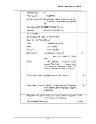
21
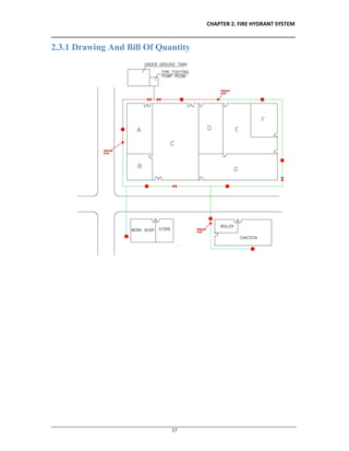
2.3.3 Hydraulic Calculation
Hydraulic calculation is the fire safety practice of calculating the flow of liquids through
a medium (usually a piping network) to ensure that fires could be extinguished.
Hydraulic calculations are required to prove the flow of water (or water mixed with
chemical additive) through piping networks for the purpose of controlling or
extinguishing a fire. The hydraulic calculation procedure is defined in the reference
model codes as published by NFPA (National Fire Protection Association),[1] EN 12845
Fixed firefighting system - Automatic sprinkler systems - Design, installation and
maintenance [2] and other international fire design standards.
The calculations prove that the water available (usually from a city water main, elevated
storage tank, or fire pump) is strong enough (has enough pressure), and plentiful enough
Calculations are based on the worst expected fire, located in the geometrically farthest
point from the water source (based on the path the extinguishing water is required to
travel to get to the fire).
Analysis of the worst expected fire is based on the use of the building and areas. The
hazard rating of various areas is defined by National Fire Protection Association (NFPA)
Codes. Areas include:
Light Hazard (offices, toilets, and similar areas of light combustibles and light fuel
loading)
Ordinary Hazard (car parking, stores, restaurants)
Extra Hazard (flammable chemical use, heavy manufacturing, plastics)
Storage (flammable items stored in solid piles, on shelves, or on racks to a significant
height).
The analysis of hazard gives a design density required to control a fire, which has been
derived from years of fire tests conducted by insurance companies and other testing
agencies. The design density is described by two variables that must work together to
achieve fire control:
Water flowfrom the sprinkler head (how heavy the rainfall of water from open fire
sprinklers)
Total area (the expected size of the fire before it will not continue to grow)
The shortened expression of a common design density for a Light Hazard office
is .1/1500, which is fully expressed as,
" 0.1 GPM per square foot is required to fall from the fire sprinklers onto the fire over the
most remote 1,500 square feet (140 m2) of area, which is the maximum expected size of a
fire in this Light Hazard building area."
A common density required for a warehouse type "big box" store that has higher
flammability items stored on racks to twenty feet high is .6/2000. Note that the density of
water to fall per square foot is six times heavier than an office, and the expected fire size
is larger.](https://image.slidesharecdn.com/d27570dc-8448-4efa-b11c-599fe8620d7b-160714052810/85/Final-Year-Project-on-Fire-Fighting-systems-30-320.jpg)

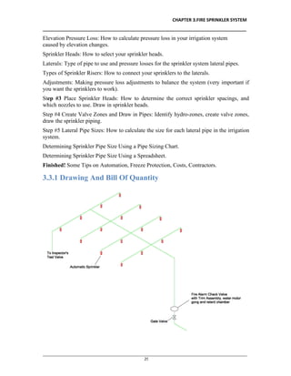
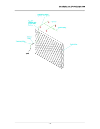
![CHAPTER 3.FIRE SPRINKLER SYSTEM
__________________________________________________________________________________
________________________________________________________________________________________________
29
3.3.3 Hydraulic Calculation
Hydraulic calculation is the fire safety practice of calculating the flow of liquids through
a medium (usually a piping network) to ensure that fires could be extinguished.
Hydraulic calculations are required to prove the flow of water (or water mixed with
chemical additive) through piping networks for the purpose of controlling or
extinguishing a fire. The hydraulic calculation procedure is defined in the reference
model codes as published by NFPA (National Fire Protection Association),[1] EN 12845
Fixed firefighting system - Automatic sprinkler systems - Design, installation and
maintenance [2] and other international fire design standards.
The calculations prove that the water available (usually from a city water main, elevated
storage tank, or fire pump) is strong enough (has enough pressure), and plentiful enough
Calculations are based on the worst expected fire, located in the geometrically farthest
point from the water source (based on the path the extinguishing water is required to
travel to get to the fire).
Analysis of the worst expected fire is based on the use of the building and areas. The
hazard rating of various areas is defined by National Fire Protection Association (NFPA)
Codes. Areas include:
Light Hazard (offices, toilets, and similar areas of light combustibles and light fuel
loading)
Ordinary Hazard (car parking, stores, restaurants)
Extra Hazard (flammable chemical use, heavy manufacturing, plastics)
Storage (flammable items stored in solid piles, on shelves, or on racks to a significant
height).
The analysis of hazard gives a design density required to control a fire, which has been
derived from years of fire tests conducted by insurance companies and other testing
agencies. The design density is described by two variables that must work together to
achieve fire control:
Water flowfrom the sprinkler head (how heavy the rainfall of water from open fire
sprinklers)
Total area (the expected size of the fire before it will not continue to grow)
The shortened expression of a common design density for a Light Hazard office
is .1/1500, which is fully expressed as,
" 0.1 GPM per square foot is required to fall from the fire sprinklers onto the fire over the
most remote 1,500 square feet (140 m2) of area, which is the maximum expected size of a
fire in this Light Hazard building area."
A common density required for a warehouse type "big box" store that has higher
flammability items stored on racks to twenty feet high is .6/2000.](https://image.slidesharecdn.com/d27570dc-8448-4efa-b11c-599fe8620d7b-160714052810/85/Final-Year-Project-on-Fire-Fighting-systems-38-320.jpg)
![CHAPTER 4.FIRE ALARM SYSTEM
__________________________________________________________________________________
________________________________________________________________________________________________
30
4.1Introduction
An automatic fire alarm system is designed to detect the unwanted presence of fire by
monitoring environmental changes associated with combustion. In general, a fire alarm
system is classified as either automatically actuated, manually actuated, or both.
Automatic fire alarm systems are intended to notify the building occupants to evacuate in
the event of a fire or other emergency, report the event to an off-premises location in
order to summon emergency services, and to prepare the structure and associated systems
to control the spread of fire and smoke.
4.2Components Of Fire Alarm System
4.2.1 Smoke Detector
4.2.2 Heat Detector
4.2.3 Sounder
4.2.4 Fire Alarm Control Panel
4.2.5 Wire
4.2.6 Pipe
4.2.7 junction Box
4.2.8 Isolator
4.3Designing Of Fire Alarm System
After the fire protection goals are established – usually by referencing the minimum
levels of protection mandated by the appropriate model building code, insurance agencies,
and other authorities – the fire alarm designer undertakes to detail specific components,
arrangements, and interfaces necessary to accomplish these goals. Equipment specifically
manufactured for these purposes are selected and standardized installation methods are
anticipated during the design. In the United States, NFPA 72, The National Fire Alarm
Code is an established and widely used installation standard.
EN 54 is mandatory standard in the European Union for Fire detection and fire alarm
systems. Every product for fire alarm systems must have a CE mark with an EN 54
standard to be delivered and installed in any country of the EU. It is a standard widely
used around the world.[1]
Fire alarm controlpanel (FACP) AKA fire alarm control unit (FACU); This component,
the hub of the system, monitors inputs and system integrity, controls outputs and relays
information.
Primary power supply: Commonly the non-switched 120 or 240 Volt Alternating Current
source supplied from a commercial power utility. In non-residential applications, a
branch circuit is dedicated to the fire alarm system and its constituents. "Dedicated
branch circuits" should not be confused with "Individual branch circuits" which supply
energy to a single appliance.
Secondary (backup) power supplies: This component, commonly consisting of sealed
lead-acid storage batteries or other emergency sources including generators, is used to
supply energy in the event of a primary power failure.](https://image.slidesharecdn.com/d27570dc-8448-4efa-b11c-599fe8620d7b-160714052810/85/Final-Year-Project-on-Fire-Fighting-systems-39-320.jpg)
![CHAPTER 4.FIRE ALARM SYSTEM
__________________________________________________________________________________
________________________________________________________________________________________________
31
Initiating devices: This component acts as an input to the fire alarm control unit and are
either manually or automatically actuated. Examples would be devices pull stations, heat
detectors, or smoke detectors. Heat and smoke detectors have different categories of both
kinds. Some categories are beam, photoelectrical, aspiration, and duct.
publicly accessible Alarm Box on a street in San Francisco.
Notification appliances: This component uses energy supplied from the fire alarm system
or other stored energy source, to inform the proximate persons of the need to take action,
usually to evacuate. This is done by means of a flashing light, strobe light,
electromechanical horn, "beeper horn", chime, bell, speaker, or a combination of these
devices. The System Sensor Spectralert Advance Horn makes a beeping sound and
electromechanical sound together.
Building safety interfaces: This interface allows the fire alarm system to control aspects
of the built environment and to prepare the building for fire, and to control the spread of
smoke fumes and fire by influencing air movement, lighting, process control, human
transport and exit.
Manually actuated devices; also known as fire alarm boxes, manual pull stations, or
simply pull stations, Break glass stations, call points or Buttons. Devices for manual fire
alarm activation, are installed to be readily located (near the exits), identified, and
operated.
Automatically actuated devices can take many forms intended to respond to any number
of detectable physical changes associated with fire: convected thermal energy; heat
detector, products of combustion; smoke detector, radiant energy; flame detector,
combustion gasses; fire gas detector, and release of extinguishing agents; water-flow
detector. The newest innovations can use cameras and computer algorithms to analyze the
visible effects of fire and movement in applications inappropriate for or hostile to other
detection methods.[2]
Notification Appliances utilize audible, visible, tactile, textual or even olfactory stimuli
(odorizer)[3][4] to alert the occupants of the need to evacuate or take action in the event](https://image.slidesharecdn.com/d27570dc-8448-4efa-b11c-599fe8620d7b-160714052810/85/Final-Year-Project-on-Fire-Fighting-systems-40-320.jpg)
![CHAPTER 4.FIRE ALARM SYSTEM
__________________________________________________________________________________
________________________________________________________________________________________________
32
of fire or other emergency. Evacuation signals may consist of simple appliances that
transmit uncoded information, coded appliances that transmit a predetermined pattern,
and or appliances that transmit audible and visible textual information such as live or
pre-recorded instructions, and illuminated message displays.
In the United States, fire alarm evacuation signals generally consist of a standardized
audible tone, with visual notification in all public and common use areas. Emergency
signals are intended to be distinct and understandable to avoid confusion with other
signals.
Temporal Code 3 is the most common audible in a modern system. It chimes three times
at one-second intervals, stops for one second, then repeats. Voice Evacuation is the
second most common audible in a modern system. Continuous is not common in a new
building or old building with modern system, but is found in lots of schools and older
buildings. Other methods include:
Audible textual appliances, which are employed as part of a fire alarm system that
includes Emergency Voice Alarm Communications (EVAC) capabilities. High reliability
speakers are used to notify the occupants of the need for action in connection with a fire
or other emergency. These speakers are employed in large facilities where general
undirected evacuation is considered impracticable or undesirable. The signals from the
speakers are used to direct the occupant's response. The system may be controlled from
one or more locations within the building known as Fire Wardens Stations, or from a
single location designated as the building Fire Command Center. Speakers are
automatically actuated by the fire alarm system in a fire event, and following a pre-alert
tone, selected groups of speakers may transmit one or more prerecorded messages
directing the occupants to safety. These messages may be repeated in one or more
languages. Trained personnel activating and speaking into a dedicated microphone can
suppress the replay of automated messages in order to initiate or relay real time voice
instructions.[5]
Some fire alarm systems utilize emergency voice alarm communication systems (EVACS)
[6] to provide pre-recorded and manual voice messages. Voice Alarm systems are
typically used in high-rise buildings, arenas and other large "defend-in-place"
occupancies such as Hospitals and Detention facilities where total evacuation is difficult
to achieve.[citation needed]
Voice-based systems provide response personnel with the ability to conduct orderly
evacuation and notify building occupants of changing event circumstances.[citation
needed]
In high rise buildings, different evacuation messages may be played to each floor,
depending on the location of the fire. The floor the fire is on along with ones above it
may be told to evacuate while floors much lower may simply be asked to stand
by.[citation needed]
New codes and standards introduced around 2010 especially the new UL Standard 2572,
the U.S. Department of Defence's UFC 4-021-01 Design and O&M Mass Notification
Systems, and NFPA 72 2010 edition Chapter 24 have led Fire Alarm System
Manufacturers to expand their systems voice evacuation capabilities to support new](https://image.slidesharecdn.com/d27570dc-8448-4efa-b11c-599fe8620d7b-160714052810/85/Final-Year-Project-on-Fire-Fighting-systems-41-320.jpg)
![CHAPTER 4.FIRE ALARM SYSTEM
__________________________________________________________________________________
________________________________________________________________________________________________
34
or to main amplifier driving this rack. the purpose is to "mute" the BGM(background
music) of this rack in case of emeregency in case of fire initiating true alarm.
There are many types of fire alarm systems each suited to different building types and
applications. A fire alarm system can vary dramatically in both price and complexity,
from a single panel with a detector and sounder in a small commercial property to an
addressable fire alarm system in a multi-occupancy building. Systems have to protect
both buildings and occupants.[7]
The categories of fire alarm systems are L if they are designed to protect life, P to protect
buildings and M if they are manual systems.
M
Manual systems, e.g. hand bells, gongs, etc. These may be purely manual or manual electric, the latter
may have call points and sounders. They rely on the occupants of the building discovering the fire and
acting to warn others by operating the system. Such systems form the basic requirement for places of
employment with no sleeping risk.
P1
The system is installed throughout the building – the objective being to call the fire brigade as early as
possible to ensure that any damage caused by fire is minimized. Small low risk areas can be excepted,
such as toilets and cupboards less than 1m².
P2
Detection should be provided in parts of the building where the risk of ignition is high and/or the contents
are particularly valuable. Category 2 systems provide fire detection in specified parts of the building
where there is either high risk or where business disruption must be minimised.
L1
A category L1 system is designed for the protection of life and which has automatic detectors installed
throughout all areas of the building (including roof spaces and voids) with the aim of providing the
earliest possible warning. A category L1 system is likely to be appropriate for the majority of residential
care premises. In practice, detectors should be placed in nearly all spaces and voids. With category 1
systems, the whole of a building is covered apart from minor exceptions.
L2
A category L2 system designed for the protection of life and which has automatic detectors installed in
escape routes, rooms adjoining escape routes and high hazard rooms. In a medium sized premises
(sleeping no more than ten residents), a category L2 system is ideal. These fire alarm systems are
identical to an L3 system but with additional detection in an area where there is a high chance of ignition,
e.g., kitchen) or where the risk to people is particularly increased (e.g., sleeping risk).
L3
This category is designed to give early warning to everyone. Detectors should be placed in all escape
routes and all rooms that open onto escape routes. Category 3 systems provide more extensive cover
than category 4. The objective is to warn the occupants of the building early enough to ensure that all are
able to exit the building before escape routes become impassable.
L4
Category 4 systems cover escape routes and circulation areas only. Therefore, detectors will be placed
in escape routes, although this may not be suitable depending on the risk assessment or if the size and](https://image.slidesharecdn.com/d27570dc-8448-4efa-b11c-599fe8620d7b-160714052810/85/Final-Year-Project-on-Fire-Fighting-systems-43-320.jpg)
![CHAPTER 4.FIRE ALARM SYSTEM
__________________________________________________________________________________
________________________________________________________________________________________________
35
complexity of a building is increased. Detectors might be sited in other areas of the building, but the
objective is to protect the escape route.
L5
This is the "all other situations" category, e.g., computer rooms, which may be protected with an
extinguishing system triggered by automatic detection. Category 5 systems are the "custom" category
and relate to some special requirement that cannot be covered by any other category.
Zoning
An important consideration when designing fire alarms is that of individual zones.[9]
Specifically:
A single zone should not exceed 2,000m² in floor space.
Where addressable systems are in place, two faults should not remove protection from an area
greater than 10,000m².
A building may be viewed as a single zone if the floor space is less than 300m².
Where the floor space exceeds 300m² then all zones should be restricted to a single floor level.
Stairwells, lift shafts or other vertical shafts (non stop risers) within a single fire compartment
should be considered as one or more separate zones.
The maximum distance traveled within a zone to locate the fire should not exceed 60m.](https://image.slidesharecdn.com/d27570dc-8448-4efa-b11c-599fe8620d7b-160714052810/85/Final-Year-Project-on-Fire-Fighting-systems-44-320.jpg)


![CHAPTER 5. DELUGE SYSTEM
____________________________________________________________________________________________
____________________________________________________________________________________________________________
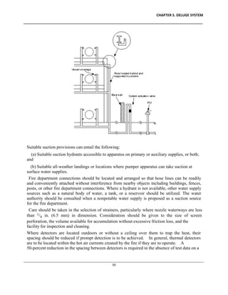
57
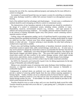
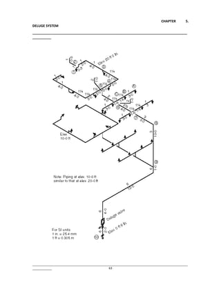
System operation for a duration of several hours may be necessary before the required activities
are completed.
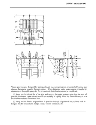
Control of burning by directional water spray is not intended to preclude the installation of
exposure protection for pump and compressor connections, exposed piping, compressor casings,
drivers, lubrication systems, and related equipment.
(a) Generally, the upper portions of equipment and the upper levels of supporting structures
are less severely exposed by fire than are the lower portions or levels, due to the accumulation at
grade level of fuel from spillage or equipment rupture. Consideration may thus be given to
reducing the degree of (or eliminating) water spray protection for the upper portions of high
equipment or levels of structures, provided a serious accumulation of fuel or torch action from
broken process piping or equipment cannot occur at these elevations and serious fire exposure
does not exist. Examples are certain types of distillation columns [above the 30-ft or 40-ft
(9.2-m or 12.2-m)] level and above the third or fourth level of multi-level open structures.
(b) The densities specified for exposure protection include a safety factor of 0.05 gpm/ft2 [2.0
(L/min)/m2] to compensate for unanticipated wastage.
In determining the duration of the exposing fire, consideration should be given to the](https://image.slidesharecdn.com/d27570dc-8448-4efa-b11c-599fe8620d7b-160714052810/85/Final-Year-Project-on-Fire-Fighting-systems-66-320.jpg)
![CHAPTER 5. DELUGE SYSTEM
____________________________________________________________________________________________
____________________________________________________________________________________________________________
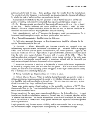
58
properties and quantities of the exposing combustibles and the anticipated effect of available
manual fire fighting. System operation for several hours may be required.
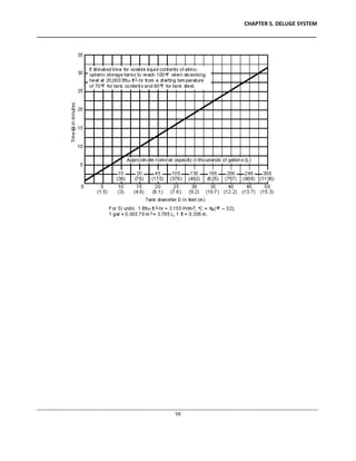
(a) It has been established that uninsulated vessels, under average plant conditions, enveloped
with flame can be expected to absorb heat at a rate of at least 20,000 Btu/hr/ft2 (63,100 W/m2) of
exposed surface wetted by the contents. Unwetted, uninsulated steel equipment absorbs heat
rapidly, and failure occurs from overpressure or overheating, or both, when such equipment is
exposed to fire. Figure A-4-5.2(a) is a time-temperature curve showing the lengths of time
required for vessels of different sizes containing volatile materials to have their contents heated
to 100qF (38qC) from a starting temperature of 70qF (21qC) for tank contents and 60qF (16qC)
for the tank steel. (See Requirements for Relief of Overpressure in Vessels Exposed to Fire;
Transactions of the ASME, January, 1944, 1-53; Venting of Tanks Exposed to Fire; and Heat
Input to Vessels.)
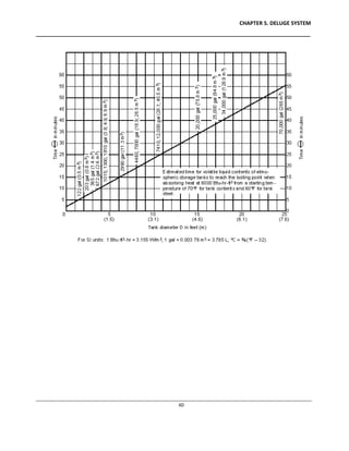
The application of water spray to a vessel enveloped by fire will reduce the heat input rate to a
value on the order of 6000 Btu/hr/ft2 (18,930 W/m2) of exposed surface wetted by the contents
where the unit rate of water application is 0.20 gpm/ft2 [8.2 (L/min)/m2] of exposed surface.
The 6000 Btu/hr/ft2 (18,930 W/m2) rate was also established in Rubber Reserve Company
Memorandum 123, Protection of Vessels Exposed to Fire, February 28, 1945. Figure A-4-5.2(b)
shows the estimated time for volatile liquid contents of atmospheric storage tanks to reach the
boiling point where absorbing heat at 6000 Btu/hr/ft2 (18,930 W/m2). This may be compared
with Figure A-4-5.2(a) to show the benefits derived from water spray systems.
(b) Where the temperature of a vessel or its contents should be limited, higher densities than
specified in 4-5.2.1 may be required.
(c) Internally insulated or lined vessels require special consideration to determine necessary
water spray requirements.](https://image.slidesharecdn.com/d27570dc-8448-4efa-b11c-599fe8620d7b-160714052810/85/Final-Year-Project-on-Fire-Fighting-systems-67-320.jpg)
![CHAPTER 5.
DELUGE SYSTEM
__________________________________________________________________________________
__________
________________________________________________________________________________________________
____________ 64
3.3.3 Designing Calculation Method
Hydraulic calculation is the fire safety practice of calculating the flow of liquids through
a medium (usually a piping network) to ensure that fires could be extinguished.
Hydraulic calculations are required to prove the flow of water (or water mixed with
chemical additive) through piping networks for the purpose of controlling or
extinguishing a fire. The hydraulic calculation procedure is defined in the reference
model codes as published by NFPA (National Fire Protection Association),[1] EN 12845
Fixed firefighting system - Automatic sprinkler systems - Design, installation and
maintenance [2] and other international fire design standards.
The calculations prove that the water available (usually from a city water main, elevated
storage tank, or fire pump) is strong enough (has enough pressure), and plentiful enough
Calculations are based on the worst expected fire, located in the geometrically farthest
point from the water source (based on the path the extinguishing water is required to
travel to get to the fire).
Analysis of the worst expected fire is based on the use of the building and areas. The
hazard rating of various areas is defined by National Fire Protection Association (NFPA)
Codes. Areas include:
Light Hazard (offices, toilets, and similar areas of light combustibles and light fuel
loading)
Ordinary Hazard (car parking, stores, restaurants)
Extra Hazard (flammable chemical use, heavy manufacturing, plastics)
Storage (flammable items stored in solid piles, on shelves, or on racks to a significant
height).
The analysis of hazard gives a design density required to control a fire, which has been
derived from years of fire tests conducted by insurance companies and other testing
agencies. The design density is described by two variables that must work together to
achieve fire control:
Water flowfrom the sprinkler head (how heavy the rainfall of water from open fire
sprinklers)
Total area (the expected size of the fire before it will not continue to grow)](https://image.slidesharecdn.com/d27570dc-8448-4efa-b11c-599fe8620d7b-160714052810/85/Final-Year-Project-on-Fire-Fighting-systems-73-320.jpg)

![CHAPTER 7.VESDA SYSTEM
__________________________________________________________________________________
________________________________________________________________________________________________
70
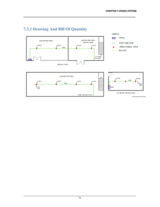
7.1 Introduction
An aspirating smoke detector (ASD), consists of a central detection unit which draws air
through a network of pipes to detect smoke.[1] The sampling chamber is based on a
nephelometer that detects the presence of smoke particles suspended in air by detecting
the light scattered by them in the chamber.
In most cases aspirating smoke detectors require a fan unit to draw in a sample of air
from the protected area through its network of pipes, such as is the case for Wagner, Safe
Fire Detection's ProSeries and Xtralis ASD systems.
7.2 Components Of Vesda System
7.2.1 Panel
7.2.2 PPRC Tube
7.2.3 VESDA Nozzle
7.2.4 End Cap
7.3 Designing Of Vesda System
ASD design corrects shortcomings of conventional smoke detectors by using sampling
pipe with multiple holes. The air samples are captured and filtered, removing any
contaminants or dust to avoid false alarms and then processed by a centralized, highly
sensitive laser detection unit. If smoke is detected, the systems alarm is triggered, and
signals then are processed through centralized monitoring stations within a few seconds.
Unlike passive smoke detection systems including spot detectors, ASD systems actively
draw smoke to the detector through bore holes within a piping system that runs
throughout the protected area. Furthermore, ASD systems incorporate integrity
monitoring to ensure an alert is raised at any time the ASD’s ability to detect smoke is
compromised. This is not the case with passive devices that are generally only electrically
monitored with no ability to determine if smoke can actually reach the detection element.
ASD systems incorporate more than one level of alarm, generally configurable. This
allows an ASD system to provide very early warning of an event, prompting investigation
at the earliest smouldering stage of a fire when it is easily addressed. Other alarm levels
may be configured to provide fire alarm inputs to fire systems as well as releasing
suppression systems. ASD alarm sensitivities are configurable and can be programmed to
levels ranging from thousands of times more sensitive than a conventional detector, to
much less sensitive. The detectors work best in non-volatile environments.They can also
be used in computer cabinets to alert users to the overheating of computer cables or
individual computer components.](https://image.slidesharecdn.com/d27570dc-8448-4efa-b11c-599fe8620d7b-160714052810/85/Final-Year-Project-on-Fire-Fighting-systems-79-320.jpg)


![CHAPTER 7.VESDA SYSTEM
__________________________________________________________________________________
________________________________________________________________________________________________
70
7.1 Introduction
An aspirating smoke detector (ASD), consists of a central detection unit which draws air
through a network of pipes to detect smoke.[1] The sampling chamber is based on a
nephelometer that detects the presence of smoke particles suspended in air by detecting
the light scattered by them in the chamber.
In most cases aspirating smoke detectors require a fan unit to draw in a sample of air
from the protected area through its network of pipes, such as is the case for Wagner, Safe
Fire Detection's ProSeries and Xtralis ASD systems.
7.2 Components Of Vesda System
7.2.1 Panel
7.2.2 PPRC Tube
7.2.3 VESDA Nozzle
7.2.4 End Cap
7.3 Designing Of Vesda System
ASD design corrects shortcomings of conventional smoke detectors by using sampling
pipe with multiple holes. The air samples are captured and filtered, removing any
contaminants or dust to avoid false alarms and then processed by a centralized, highly
sensitive laser detection unit. If smoke is detected, the systems alarm is triggered, and
signals then are processed through centralized monitoring stations within a few seconds.
Unlike passive smoke detection systems including spot detectors, ASD systems actively
draw smoke to the detector through bore holes within a piping system that runs
throughout the protected area. Furthermore, ASD systems incorporate integrity
monitoring to ensure an alert is raised at any time the ASD’s ability to detect smoke is
compromised. This is not the case with passive devices that are generally only electrically
monitored with no ability to determine if smoke can actually reach the detection element.
ASD systems incorporate more than one level of alarm, generally configurable. This
allows an ASD system to provide very early warning of an event, prompting investigation
at the earliest smouldering stage of a fire when it is easily addressed. Other alarm levels
may be configured to provide fire alarm inputs to fire systems as well as releasing
suppression systems. ASD alarm sensitivities are configurable and can be programmed to
levels ranging from thousands of times more sensitive than a conventional detector, to
much less sensitive. The detectors work best in non-volatile environments.They can also
be used in computer cabinets to alert users to the overheating of computer cables or
individual computer components.](https://image.slidesharecdn.com/d27570dc-8448-4efa-b11c-599fe8620d7b-160714052810/85/Final-Year-Project-on-Fire-Fighting-systems-83-320.jpg)

![CHAPTER 8.FM 200 SYSTEM
__________________________________________________________________________________
________________________________________________________________________________________________
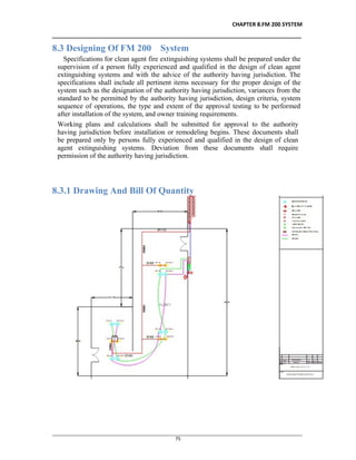
74
8.1 Introduction
HFC-227ea finds use in fire suppression systems in data processing and
telecommunication facilities, and in protection of many flammable liquids and gases.
HFC-227ea falls in the category of Clean Agents and is governed by NFPA 2001 -
Standard for Clean Agent Fire Extinguishing Systems. Effective fire suppression requires
introducing a concentration of the HFC-227ea agent between 6.25% and 9% depending
on the hazard being protected. Its NOAEL level for cardiac sensitization is 9%. The
United States Environmental Protection Agency allows concentration of 9% volume in
occupied spaces without mandated egress time, or up to 10.5% for a limited time. Most
fire suppression systems are designed to provide concentration of 6.25-9%.
The HFC-227ea fire suppression agent was the first non-ozone depleting replacement for
Halon 1301.[citation needed] In addition, HFC-227ea leaves no residue on valuable
equipment after discharge.
HFC-227ea contains no chlorine or bromine atoms, presenting no ozone depletion effect.
Its atmospheric lifetime is approximated between 31 and 42 years. It leaves no residue or
oily deposits and can be removed by ventilation of the affected space.
As an aerosol propellant, HFC-227ea is used in pharmaceutical metered dose inhalers
such as those used for dispensing asthma medication.
8.2 Components Of FM 200 System
8.2.1 Smoke Detector / Heat Detector
8.2.2 Manual Call point
8.2.3 Audible alarm
8.2.4 Visual alarm
8.2.5 Abort Switch
8.2.6 FM-200 Cylinder
8.2.7 Manual Actuator
8.2.8 2-way Pneumatic Head
8.2.9 1-Way Pneumatic Head
8.2.10 Extinguishing Control Panel
8.2.11 Piping
8.2.12 Discharge nozzles
8.2.13 Manifold
8.2.14 Release hose
8.2.15 Discharge hose](https://image.slidesharecdn.com/d27570dc-8448-4efa-b11c-599fe8620d7b-160714052810/85/Final-Year-Project-on-Fire-Fighting-systems-87-320.jpg)
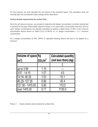
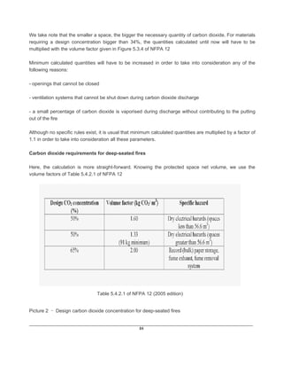
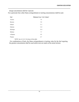
![CHAPTER 9.CO2 SYSTEM
____________________________________________________________________________________________
____________________________________________________________________________________________________________
81
9.1 Introduction
Carbon dioxide (chemical formula CO2) is a naturally occurring chemical compound composed of
two oxygen atoms each covalently double bonded to a single carbon atom. It is a gas at standard
temperature and pressure and exists in Earth's atmosphere in this state, as a trace gas at a
concentration of 0.039 per cent by volume.[1]
As part of the carbon cycle, plants, algae, and cyanobacteria use light energy to photosynthesize
carbohydrate from carbon dioxide and water, with oxygen produced as a waste product.[2] However,
photosynthesis cannot occur in darkness and at night some carbon dioxide is produced by plants
during respiration.[3] Carbon dioxide is produced by combustion of coal or hydrocarbons, the
fermentation of sugars in beer and winemaking and by respiration of all living organisms. It is
exhaled in the breath of humans and other land animals. It is emitted from volcanoes, hot springs,
geysers and other places where the earth's crust is thin and is freed from carbonate rocks by
dissolution. CO2 is also found in lakes, at depth under the sea and commingled with oil and gas
deposits.
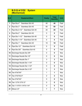
9.2 Components Of Co2 System
9.2.1 Smoke Detector / Heat Detector
9.2.2 Manual Call point
9.2.3 Audible alarm
9.2.4 Visual alarm
9.2.5 Abort Switch
9.2.6 CO2 Cylinder
9.2.7 Pilot Cylinder
9.2.8 Manual Actuator
9.2.9 2-way Pneumatic Head
9.2.10 1-Way Pneumatic Head
9.2.11 Extinguishing Control Panel
9.2.12 Piping
9.2.13 Discharge nozzles
9.2.14 Manifold
9.2.15 Release hose
9.2.16 Discharge hose](https://image.slidesharecdn.com/d27570dc-8448-4efa-b11c-599fe8620d7b-160714052810/85/Final-Year-Project-on-Fire-Fighting-systems-94-320.jpg)