Downloaded 505 times

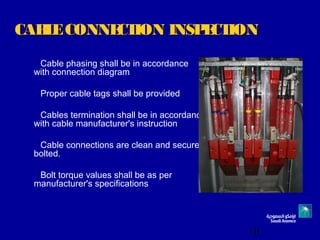
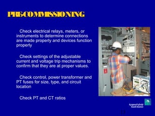
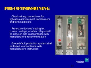
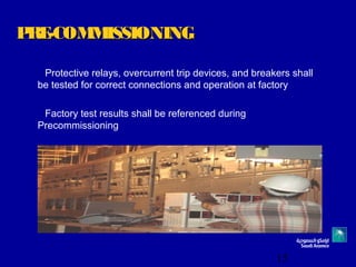

This document provides guidelines for inspecting and testing metal-clad switchgear during installation and pre-commissioning. It outlines requirements for equipment installation, busbar installation, cable connections, grounding connections and pre-commissioning tests. Key steps include ensuring proper spacing and anchoring of switchgear, exercising operating mechanisms, checking tightness of connections, testing insulation resistance, setting protective relays and testing auxiliary equipment operation. The purpose is to verify proper installation and functioning of switchgear before energization.


