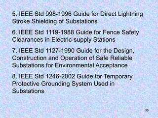
1. The document describes the design and construction of a 115kV substation. It includes sections on substation design, construction, civil and structural design, mechanical design, electrical design, and reference standards.
2. Key aspects of the design include civil and structural elements like foundations, drainage, and oil containment. The electrical design covers protection, communication, grounding and circuit breakers.
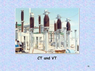
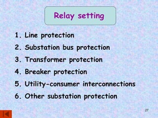
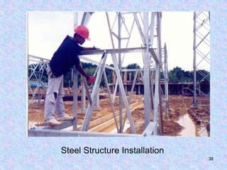
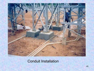
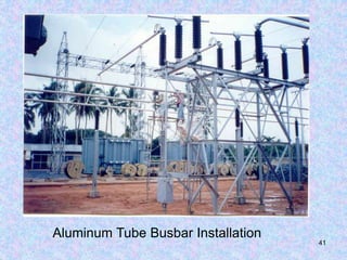
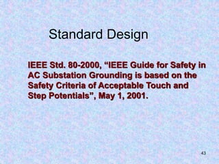
3. Construction includes installing high-voltage equipment, transformers, switchgear, protection relays and control systems. Commissioning involves testing, relay settings and training personnel on equipment operation and maintenance.
The document is a checklist to commission various AC Side equipment - Transformers (Power, Auxillary & Inverter) , HT Panels, Relays, Circuit Breakers, LA, CT, PT, C&R Panel.
This Presentation is about l.v switch gear design, presented during the graduation project final discussion 15/7/2018.
It presented a good summary of switch gear components and types and practicing on AL.HAMOOL W.T.P M.D.B design using SIEMENS SIVACON S8
Transformer vector group_test_conditionsSARAVANAN A
Test Conditions for various vector groups commonly under use are listed along with pictorial representation. Assuming the reader has sufficient exposure to transformer winding connections.
Transformer Vector Group Test conditions
YNd1, YNd11, Dyn11, YNyn0and more
Successful operation of entire power system depends to a considerable extent on efficient and satisfactory performance of substations. Hence substations in general can be considered as heart of overall power system. In any substation, a well-designed grounding plays an important role. Since absence of safe and effective grounding system can result in mal-operation or non-operation of control and protective devices, grounding system design deserves considerable attention for all the substations. There are two primary functions of a safe earthing system. Firstly, ensure that a person who is in the vicinity of earthed facilities during a fault is not exposed to the possibility of a fatal electrical shock. Secondly, provide a low impedance path to earth for currents occurring under normal and fault conditions.The earthing conductors, composing the grid and connections to all equipment and structures, must possess sufficient thermal capacity to pass the highest fault current for the required time
MV Switchgear provides centralized control and protection of medium-voltage power equipment and circuits in industrial, commercial, and utility installations involving generators, motors, feeder circuits, and transmission and distribution lines.
Installation Operation & Maintenance of 33kV & 11kV SwitchgearSheikh Nazmul Islam
In-Country Training On Operation, Maintenance, Protection & Control of 33/11 kV Substation Project Name: Design, Supply, Installation, Testing & Commissioning of 33/11 kV sub-stations with source end feeder bays. Contract No: BREB/UREDS/W-01A-001/02/2016-2017 BREB/UREDS/W-01A-002/03/2016-2017 BREB/UREDS/W-01A-004/04/2016-2017
Design of Earthing System for 230 kV High Voltage Substation by ETAP 12.6 Sof...ijtsrd
The design of earthing system for 230 kV substation is challenging task. A safety is one major concern in the operation and design of an electrical power system. This Paper is to provide information pertinent to safe earthing practice in substation design and to establish the safe limits of potential difference under normal and fault conditions. Substation earthing system design requires calculating of parameter such as touch and step voltage criteria for safety, grid resistance, maximum grid current, earth resistance, minimum conductor size and electrode size, maximum fault current level and soil resistivity. Soil resistivity is a major factor influencing substation grid design. In this paper, design of earthing grid for Square configuration to obtain the minimum cost and safety. Finally, simulation results were carried out using ETAP 12.6 software. This paper mentions the method proposed for substation earthing is in accordance with IEEE Std 80 2000. Khin Thuzar Soe | Thet Mon Aye | Aye Aye Mon "Design of Earthing System for 230 kV High Voltage Substation by ETAP 12.6 Software" Published in International Journal of Trend in Scientific Research and Development (ijtsrd), ISSN: 2456-6470, Volume-3 | Issue-5 , August 2019, URL: https://www.ijtsrd.com/papers/ijtsrd26747.pdf Paper URL: https://www.ijtsrd.com/engineering/electrical-engineering/26747/design-of-earthing-system-for-230-kv-high-voltage-substation-by-etap-126-software/khin-thuzar-soe
Testing and Condition Monitoring of Substation EquipmentsSumeet Ratnawat
Testing and condition monitoring of substation equipments,Transformer specifications,Monitoring of Transformer,On-load Tap changer,Overhauling,Tan delta and capacitance,Thermal imaging,Sweep frequency response analysis,Oil analysis of Switchgear elements containing oil,tests on insulating oil,Breaker monitoring,Condition monitoring of CT,Condition monitoring of CVT,Surge Arresters,Condition monitoring of relays.
Comparision Lightning Protection Systems s per IEC 62305-3 and NFC 17-102(2011)/UNE21-1186 India NBC2016 / Project Building and Infra Projects /MEP ,Architect ,Electrical Consultants
Lightning is Disaster when it's hit to Surface and damage only possible to assess Lost of Human Lives and Assets.
The Agencies who claim Said Protection is from Lightning Product ,Design and Installation is Accordingly EN62305/IEC62305 and NFC17-102 .
Lightning Protection Standard Committee member is from Industries who are having Experience ,Knowledge and they are business man and better know how to safe guard to make more profit from their Business like other Industries.
If we Compare One Area Like Calculation Hight , Lenght and Width as per ZONE 1,2,3&4 Now Threat from Lightning Design as per IEC62305 and Prepare BOQ Considering Reputed Makes from Manufacturer .
According to IEC62305 our Cost will be 3-5 Time High as Compare to NFC17-102.
Now you can understand why IEC do not support NFC .
Latest now CENELEC Given their Acceptance Mentioning IEC 62035 and NFC17-102 not having any Conflict and Claims are Different and Accepted by Countries.
Plz go through presentation.
In India Lightning Documents is adopted under National Disaster and Every State is Declare Documents to offer Awareness Common Public what action they have to do.
NFC17-102 Acceptance in India CERC,SECI,RDSO.CPWD,PWD and Other Industries and Growing because We want to have Protection from Lightning ,
Fire-Alarm-Installation as per NFPA.pdfOfficeMobile1
Fire Alarm System Installation and Design Guide in line with NFPA requirements, giving the basic guide on how to design system, choose devices and install these in line with the stipulated requirements.
To download head to http://solarreference.com/solar-pv-codes-brooks/
Also available on the Brook Solar website (they have some quality stuff)
This presentation from Brook Solar (Now Brooks Engineering LLC) is a wonderful compilation of the standards in place in the PV industry. But you do know that standards are like babies, they don't stop growing!
For more quality information visit http://solarreference.com/
CFD Simulation of By-pass Flow in a HRSG module by R&R Consult.pptxR&R Consult
CFD analysis is incredibly effective at solving mysteries and improving the performance of complex systems!
Here's a great example: At a large natural gas-fired power plant, where they use waste heat to generate steam and energy, they were puzzled that their boiler wasn't producing as much steam as expected.
R&R and Tetra Engineering Group Inc. were asked to solve the issue with reduced steam production.
An inspection had shown that a significant amount of hot flue gas was bypassing the boiler tubes, where the heat was supposed to be transferred.
R&R Consult conducted a CFD analysis, which revealed that 6.3% of the flue gas was bypassing the boiler tubes without transferring heat. The analysis also showed that the flue gas was instead being directed along the sides of the boiler and between the modules that were supposed to capture the heat. This was the cause of the reduced performance.
Based on our results, Tetra Engineering installed covering plates to reduce the bypass flow. This improved the boiler's performance and increased electricity production.
It is always satisfying when we can help solve complex challenges like this. Do your systems also need a check-up or optimization? Give us a call!
Work done in cooperation with James Malloy and David Moelling from Tetra Engineering.
More examples of our work https://www.r-r-consult.dk/en/cases-en/
Hierarchical Digital Twin of a Naval Power SystemKerry Sado
A hierarchical digital twin of a Naval DC power system has been developed and experimentally verified. Similar to other state-of-the-art digital twins, this technology creates a digital replica of the physical system executed in real-time or faster, which can modify hardware controls. However, its advantage stems from distributing computational efforts by utilizing a hierarchical structure composed of lower-level digital twin blocks and a higher-level system digital twin. Each digital twin block is associated with a physical subsystem of the hardware and communicates with a singular system digital twin, which creates a system-level response. By extracting information from each level of the hierarchy, power system controls of the hardware were reconfigured autonomously. This hierarchical digital twin development offers several advantages over other digital twins, particularly in the field of naval power systems. The hierarchical structure allows for greater computational efficiency and scalability while the ability to autonomously reconfigure hardware controls offers increased flexibility and responsiveness. The hierarchical decomposition and models utilized were well aligned with the physical twin, as indicated by the maximum deviations between the developed digital twin hierarchy and the hardware.
Cosmetic shop management system project report.pdfKamal Acharya
Buying new cosmetic products is difficult. It can even be scary for those who have sensitive skin and are prone to skin trouble. The information needed to alleviate this problem is on the back of each product, but it's thought to interpret those ingredient lists unless you have a background in chemistry.
Instead of buying and hoping for the best, we can use data science to help us predict which products may be good fits for us. It includes various function programs to do the above mentioned tasks.
Data file handling has been effectively used in the program.
The automated cosmetic shop management system should deal with the automation of general workflow and administration process of the shop. The main processes of the system focus on customer's request where the system is able to search the most appropriate products and deliver it to the customers. It should help the employees to quickly identify the list of cosmetic product that have reached the minimum quantity and also keep a track of expired date for each cosmetic product. It should help the employees to find the rack number in which the product is placed.It is also Faster and more efficient way.
Water scarcity is the lack of fresh water resources to meet the standard water demand. There are two type of water scarcity. One is physical. The other is economic water scarcity.
Welcome to WIPAC Monthly the magazine brought to you by the LinkedIn Group Water Industry Process Automation & Control.
In this month's edition, along with this month's industry news to celebrate the 13 years since the group was created we have articles including
A case study of the used of Advanced Process Control at the Wastewater Treatment works at Lleida in Spain
A look back on an article on smart wastewater networks in order to see how the industry has measured up in the interim around the adoption of Digital Transformation in the Water Industry.
4. 4
Civil and structural design
1. Site preparation
2. Soil sterilization
3. Drainage
4. Foundations and structures
5. Oil containment
5. 5
Reference Standards:
1. ACI 117-90, Standard tolerances for concrete
construction and materials.
2. ACI 301-96, Specifications for structural
concrete for buildings.
3. ACI 304-89, Guide for measuring, mixing,
transporting and placing concrete.
6. 6
1. Heating, ventilation and air condition
2. Water and sewer connection
3. Noise abatement facility
4. Level of fire protection
5. Levels of exhaust emissions
Mechanical design
7. 7
1. ACI 305-91, Hot weather concreting.
2. ACI 306-88, Cold weather concreting.
3. ACI 318-99, Building code requirements for
reinforced concrete & commentary.
4. ANSI B18.12-1962, American national standard
glossary of terms for mechanical fasteners.
5. ANSI C29.9-1983, American national standard
for wet-process porcelain insulators.
Reference Standards:
8. 8
Electrical design
1. Protection and control design
2. Communication design
3. Grounding and shielding
4. Circuit breaker,
5. Instrumentation and metering
9. 9
1. Accredited standard committee C2-1997,
National electrical safety code.
2. ANSI C37.06-1997, American national standard
for switchgear AC high voltage circuit breakers
rated on a symmetrical current basis preferred
ratings and related required capabilities.
3. ANSI C37.12-1991, American national standard
specification guide for AC high voltage circuit
breaker based on a symmetrical current basis.
Reference Standards:
10. 10
4. ANSI C37.32-1996, American national
standard for switchgear high voltage air
switches, bus supports, and switch accessories
schedules of preferred ratings, manufacturing
specifications, and applications guide.
5. ANSI C57.12.10-1988, American national
standard for transformers.
6. ANSI C57.12.11-1980, American national
standard guide for installation of oil immersed
transformers (10 MVA, 69-287 kV rating)
Reference Standards: (Cont.)
11. 11
7. ANSI C93.4-1984, American national standard
for power line carrier line tuning equipment.
8. ANSI C298-1985, American national standard
for wet process porcelain insulators
9. ANSI 14.15-1988, American national standard
electrical and electronic diagram
10. ANSI/NAAMM MBG531-1993, Metal bar
grating manual
Reference Standards: (Cont.)
12. 12
11. IEEE Std 48-1996, IEEE standard test
procedures and requirements for alternating
current cable.
12. IEEE Std 80-2000, IEEE guide for safety in AC
substation grounding.
13. IEEE Std 485-1997. IEEE recommended
practice for sizing lead acid batteries for
stationary applications.
14. IEEE Std 605-1998, IEEE guide for the design
of substation rigid-bus structures.
Reference Standards: (Cont.)
13. 13
15. IEEE Std 998-1996, IEEE guide for direct
lightning stroke shielding of substation.
16. IEEE Std 1264-1993, IEEE guide for animal
deterrents for electric power supply substation.
17. IEEE Std C37.010-1988, IEEE application
guide for AC high voltage circuit breakers rated
on a symmetrical current basis.
18. IEEE Std C37-30-1997, IEEE standard
requirements for high voltage switches.
Reference Standards: (Cont.)
14. 14
Construction
1. Grading specifications
2. Foundation specifications
3. Structures
4. Fence specifications
5. Bus and equipment
6. Testing and monitoring
7. Compliance with applicable regulation
27. 27
Relay setting
1. Line protection
2. Substation bus protection
3. Transformer protection
4. Breaker protection
5. Utility-consumer interconnections
6. Other substation protection
28. 28
Testing and Commissioning
1. Testing standards
2. Test and records to provide positive
assurance
3. Operation and maintenance training
29. 29
Operation and
Maintenance Training
1. Location and identification of major
equipment components
2. Demonstration of equipment maintenance
techniques
3. Demonstration of equipment operation,
both locally and remote
30. 30
4. Overview of the indicating instruments in
the panels
5. Overview of the protective relay system,
definition of zones covered by each relay,
implication of trips, techniques for setting
trip points
Operation and Maintenance Training (Cont.)
33. 33
Electrical Design
General
1. Coordination with other design groups
2. Preliminary and ultimate substation layout
to establish size requirements in
consultation with the other design groups
3. Animal deterrent designs required for the
substation
4. Ultimate low-voltage AC station service
load requirements for the equipment at
the substation
34. 34
5. Sources of the preferred and alternate AC
station power service
6. All control measurement, indication, and
protection design, including wiring
35. 35
1. IEEE Std 525-1992 Guide for the Design and
Installation of Cable Systems in Substations
2. IEEE Std 605-1998 Guide for Design of
Substation Rigid-Bus Structures
3. IEEE Std 837-2002 Standard for Qualifying
Permanent Connections Used in Substation
Grounding
4. IEEE Std 979-1984 Guide for Substation Fire
Protection
36. 36
5. IEEE Std 998-1996 Guide for Direct Lightning
Stroke Shielding of Substations
6. IEEE Std 1119-1988 Guide for Fence Safety
Clearances in Electric-supply Stations
7. IEEE Std 1127-1990 Guide for the Design,
Construction and Operation of Safe Reliable
Substations for Environmental Acceptance
8. IEEE Std 1246-2002 Guide for Temporary
Protective Grounding System Used in
Substations
43. 43
Standard Design
IEEE Std. 80-2000, “IEEE Guide for Safety in
AC Substation Grounding is based on the
Safety Criteria of Acceptable Touch and
Step Potentials”, May 1, 2001.
50. 50
IEEE Std.81.2-1991, “IEEE Guide for
Measurement of Impedance and Safety
Characteristics of Large, Extended or
Interconnected Grounding System”, June
25, 1992.
Standard Measurement
52. 52
Standard Design
1. Accredited standard committee C2-1997,
National electrical safety code.
2. ACI 117-90, Standard tolerances for
concrete construction and materials.
3. ACI 301-96, Specifications for structural
concrete for buildings.
4. ACI 304-89, Guide for measuring, mixing,
transporting and placing concrete.
53. 53
5. ACI 305-91, Hot weather concreting.
6. ACI 306-88, Cold weather concreting.
7. ACI 318-99, Building code requirements
for reinforced concrete & commentary.
8. ANSI B18.12-1962, American national
standard glossary of terms for mechanical
fasteners.
9. ANSI C29.9-1983, American national
standard for wet-process porcelain
insulators.
54. 54
10. ANSI C37.06-1997, American national
standard for switchgear AC high voltage
circuit breakers rated on a symmetrical
current basis preferred ratings and related
required capabilities.
11. ANSI C37.12-1991, American national
standard specification guide for AC high
voltage circuit breaker based on a
symmetrical current basis.
55. 55
12. ANSI C37.32-1996, American national
standard for switchgear high voltage air
switches, bus supports, and switch
accessories schedules of preferred
ratings, manufacturing specifications, and
applications guide.
13. ANSI C57.12.10-1988, American
national standard for transformers.
14. ANSI C57.12.11-1980, American national
standard guide for installation of oil
immersed transformers (10 MVA, 69-287
kV rating)
56. 56
15. ANSI C57.12.12-1980, American national
standard guide for installation of oil
immersed transformers 345 kV and above
16. ANSI C63.2-1996, American national
standard for electromagnetic noise and field
strength instrumentation, 10 kHz to 40 GHz.
17. ANSI C93.2-1976, American national
standard requirements for power line
coupling capacitor voltage transformers.
18. ANSI C93.3-1981, American national
standard for power line carrier line traps.
57. 57
19. ANSI C93.4-1984, American national
standard for power line carrier line tuning
equipment.