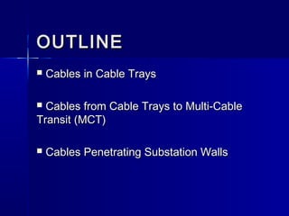
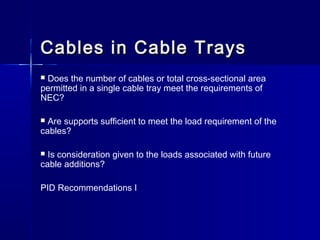
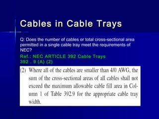
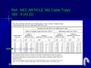
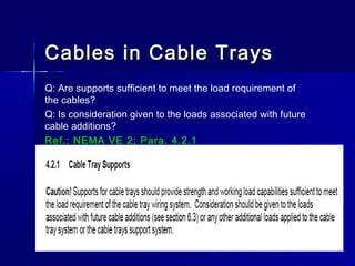
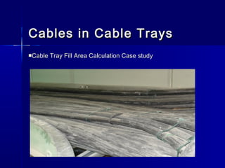
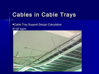
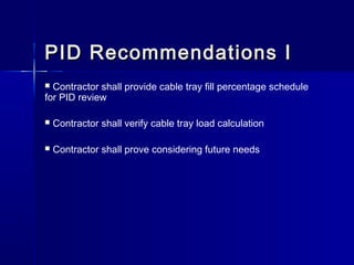
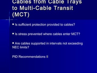
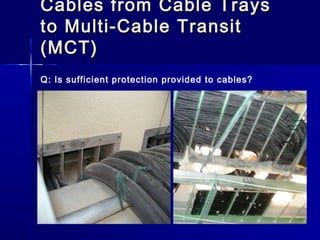
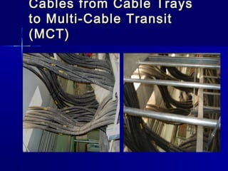
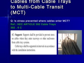
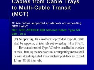
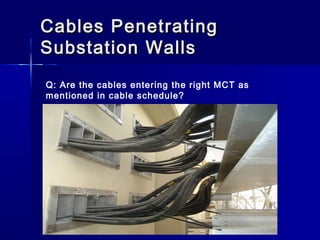
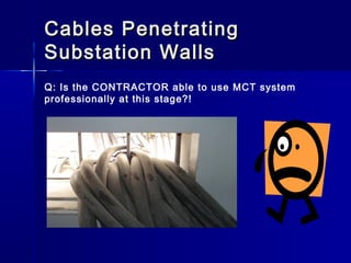
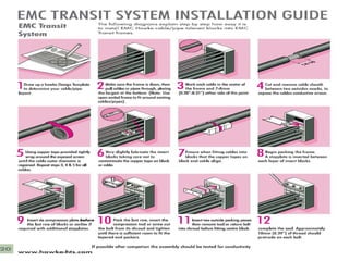
CABLE PENETRATIONCABLE PENETRATION
THROUGH SUBSTATIONTHROUGH SUBSTATION
WALLS AT KGPWALLS AT KGP
Presented by:Presented by:
Abdullah Al-DushaishiAbdullah Al-Dushaishi
Electrical Quality EngineerElectrical Quality Engineer
KPIS/KGPIUKPIS/KGPIU
July 2007July 2007
OUTLINEOUTLINE
 Cables in Cable TraysCables in Cable Trays
 Cables from Cable Trays to Multi-CableCables from Cable Trays to Multi-Cable
Transit (MCT)Transit (MCT)
 Cables Penetrating Substation WallsCables Penetrating Substation Walls
Cables in Cable TraysCables in Cable Trays
 Does the number of cables or total cross-sectional area
permitted in a single cable tray meet the requirements of
NEC?
 Are supports sufficient to meet the load requirement of the
cables?
 Is consideration given to the loads associated with future
cable additions?
PID Recommendations I
Cables in Cable TraysCables in Cable Trays
Q: Does the number of cables or total cross-sectional area
permitted in a single cable tray meet the requirements of
NEC?
Ref.: NEC ARTICLE 392 Cable Trays
392 . 9 (A) (2)
Ref.: NEC ARTICLE 392 Cable Trays
392 . 9 (A) (2)
Cables in Cable TraysCables in Cable Trays
Q: Are supports sufficient to meet the load requirement of
the cables?
Q: Is consideration given to the loads associated with future
cable additions?
Ref.: NEMA VE 2; Para. 4.2.1
Cables in Cable TraysCables in Cable Trays
Cable Tray Fill Area Calculation Case study
Cables in Cable TraysCables in Cable Trays
Cable Tray Support Design Calculation
81.67 kg/m
Cables in Cable TraysCables in Cable Trays
CableCable
Tray #Tray #
Cable SizeCable Size
No. ofNo. of
CablesCables
Area ofArea of
CablesCables
(mm2)(mm2)
Total AreaTotal Area
(mm2)(mm2)
CableCable
TrayTray
Fill %Fill %
CablesCables
WeightWeight
kg/mkg/m
CableCable
TrayTray
Load %Load %
233-415233-415
3C-35+1C-3C-35+1C-
1616
6262 43825.3243825.32
74259.5774259.57 412.55%412.55%
239.183239.183
66
292.87%292.87%
19C-2.519C-2.5 6262 30434.2530434.25
233-32233-32
3C-35+1C-3C-35+1C-
1616
3232 22619.5222619.52
38327.5238327.52 212.93%212.93%
123.449123.449
66
151.16%151.16%
19C-2.519C-2.5 3232 15708.0015708.00
PID Recommendations IPID Recommendations I
 Contractor shall provide cable tray fill percentage schedule
for PID review
 Contractor shall verify cable tray load calculation
 Contractor shall prove considering future needs
Cables from Cable TraysCables from Cable Trays
to Multi-Cable Transitto Multi-Cable Transit
(MCT)(MCT)
 Is sufficient protection provided to cables?
 Is stress prevented where cables enter MCT?
 Are cables supported in intervals not exceeding
NEC limits?
PID Recommendations II
Cables from Cable TraysCables from Cable Trays
to Multi-Cable Transitto Multi-Cable Transit
(MCT)(MCT)
Q: Is sufficient protection provided to cables?
Cables from Cable TraysCables from Cable Trays
to Multi-Cable Transitto Multi-Cable Transit
(MCT)(MCT)
Cables from Cable TraysCables from Cable Trays
to Multi-Cable Transitto Multi-Cable Transit
(MCT)(MCT)
Q: Is stress prevented where cables enter MCT?
Ref.: NEC ARTICLE 392 Cable Trays
392 . 6 C
Cables from Cable TraysCables from Cable Trays
to Multi-Cable Transitto Multi-Cable Transit
(MCT)(MCT)
Q: Are cables supported at intervals not exceeding
NEC limits?
Ref.: NEC ARTICLE 320 Armored Cable: Type AC
320 . 30 C
PID Recommendations IIPID Recommendations II
 Contractor shall make sample installation for protection the cable
from the tray sharp edge.
This sample shall be accepted by PID and the PROPONANT.
 Contractor shall prevent stress for the cable everywhere
 Contractor shall verify that cables supported in intervals not
exceeding NEC limits
Contractor shall avoid supporting the cable by the structure
 Contractor shall use T-fittings to solve all problems wherever he
can
Cables PenetratingCables Penetrating
Substation WallsSubstation Walls
Are the cables entering the right MCT as mentioned in
cable schedule?
 Is the CONTRACTOR able to use MCT professionally in
this stage?
PID Recommendations III
Cables PenetratingCables Penetrating
Substation WallsSubstation Walls
Q: Are the cables entering the right MCT as
mentioned in cable schedule?
Cables PenetratingCables Penetrating
Substation WallsSubstation Walls
Q: Is the CONTRACTOR able to use MCT system
professionally at this stage?!
Cables PenetratingCables Penetrating
Substation WallsSubstation Walls
Hawke Transit System Catalogue
PID Recommendations IIIPID Recommendations III
 Contractor shall make sample installation of MCT
Thank You

CABLE PENETRATION IN KGP SUBSTATIONS

  • 1.
    CABLE PENETRATIONCABLE PENETRATION THROUGHSUBSTATIONTHROUGH SUBSTATION WALLS AT KGPWALLS AT KGP Presented by:Presented by: Abdullah Al-DushaishiAbdullah Al-Dushaishi Electrical Quality EngineerElectrical Quality Engineer KPIS/KGPIUKPIS/KGPIU July 2007July 2007
  • 2.
    OUTLINEOUTLINE  Cables inCable TraysCables in Cable Trays  Cables from Cable Trays to Multi-CableCables from Cable Trays to Multi-Cable Transit (MCT)Transit (MCT)  Cables Penetrating Substation WallsCables Penetrating Substation Walls
  • 3.
    Cables in CableTraysCables in Cable Trays  Does the number of cables or total cross-sectional area permitted in a single cable tray meet the requirements of NEC?  Are supports sufficient to meet the load requirement of the cables?  Is consideration given to the loads associated with future cable additions? PID Recommendations I
  • 4.
    Cables in CableTraysCables in Cable Trays Q: Does the number of cables or total cross-sectional area permitted in a single cable tray meet the requirements of NEC? Ref.: NEC ARTICLE 392 Cable Trays 392 . 9 (A) (2)
  • 5.
    Ref.: NEC ARTICLE392 Cable Trays 392 . 9 (A) (2)
  • 6.
    Cables in CableTraysCables in Cable Trays Q: Are supports sufficient to meet the load requirement of the cables? Q: Is consideration given to the loads associated with future cable additions? Ref.: NEMA VE 2; Para. 4.2.1
  • 7.
    Cables in CableTraysCables in Cable Trays Cable Tray Fill Area Calculation Case study
  • 8.
    Cables in CableTraysCables in Cable Trays Cable Tray Support Design Calculation 81.67 kg/m
  • 9.
    Cables in CableTraysCables in Cable Trays CableCable Tray #Tray # Cable SizeCable Size No. ofNo. of CablesCables Area ofArea of CablesCables (mm2)(mm2) Total AreaTotal Area (mm2)(mm2) CableCable TrayTray Fill %Fill % CablesCables WeightWeight kg/mkg/m CableCable TrayTray Load %Load % 233-415233-415 3C-35+1C-3C-35+1C- 1616 6262 43825.3243825.32 74259.5774259.57 412.55%412.55% 239.183239.183 66 292.87%292.87% 19C-2.519C-2.5 6262 30434.2530434.25 233-32233-32 3C-35+1C-3C-35+1C- 1616 3232 22619.5222619.52 38327.5238327.52 212.93%212.93% 123.449123.449 66 151.16%151.16% 19C-2.519C-2.5 3232 15708.0015708.00
  • 10.
    PID Recommendations IPIDRecommendations I  Contractor shall provide cable tray fill percentage schedule for PID review  Contractor shall verify cable tray load calculation  Contractor shall prove considering future needs
  • 11.
    Cables from CableTraysCables from Cable Trays to Multi-Cable Transitto Multi-Cable Transit (MCT)(MCT)  Is sufficient protection provided to cables?  Is stress prevented where cables enter MCT?  Are cables supported in intervals not exceeding NEC limits? PID Recommendations II
  • 12.
    Cables from CableTraysCables from Cable Trays to Multi-Cable Transitto Multi-Cable Transit (MCT)(MCT) Q: Is sufficient protection provided to cables?
  • 13.
    Cables from CableTraysCables from Cable Trays to Multi-Cable Transitto Multi-Cable Transit (MCT)(MCT)
  • 14.
    Cables from CableTraysCables from Cable Trays to Multi-Cable Transitto Multi-Cable Transit (MCT)(MCT) Q: Is stress prevented where cables enter MCT? Ref.: NEC ARTICLE 392 Cable Trays 392 . 6 C
  • 15.
    Cables from CableTraysCables from Cable Trays to Multi-Cable Transitto Multi-Cable Transit (MCT)(MCT) Q: Are cables supported at intervals not exceeding NEC limits? Ref.: NEC ARTICLE 320 Armored Cable: Type AC 320 . 30 C
  • 16.
    PID Recommendations IIPIDRecommendations II  Contractor shall make sample installation for protection the cable from the tray sharp edge. This sample shall be accepted by PID and the PROPONANT.  Contractor shall prevent stress for the cable everywhere  Contractor shall verify that cables supported in intervals not exceeding NEC limits Contractor shall avoid supporting the cable by the structure  Contractor shall use T-fittings to solve all problems wherever he can
  • 17.
    Cables PenetratingCables Penetrating SubstationWallsSubstation Walls Are the cables entering the right MCT as mentioned in cable schedule?  Is the CONTRACTOR able to use MCT professionally in this stage? PID Recommendations III
  • 18.
    Cables PenetratingCables Penetrating SubstationWallsSubstation Walls Q: Are the cables entering the right MCT as mentioned in cable schedule?
  • 19.
    Cables PenetratingCables Penetrating SubstationWallsSubstation Walls Q: Is the CONTRACTOR able to use MCT system professionally at this stage?!
  • 20.
    Cables PenetratingCables Penetrating SubstationWallsSubstation Walls Hawke Transit System Catalogue
  • 22.
    PID Recommendations IIIPIDRecommendations III  Contractor shall make sample installation of MCT
  • 23.