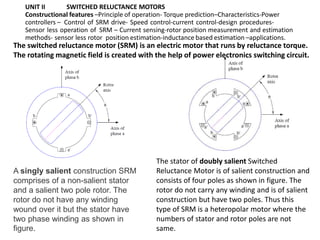
AY 23-24 Roever Engineering College Electrical and Electronics V Semester
EE3009
SPECIAL ELECTRICAL MACHINES
UNIT II
SWITCHED RELUCTANCE
MOTORS
ANBALAGAN G
Assistant Professor
Electrical and Electronics Engineering
Roever Engineering College
UNIT II SWITCHED RELUCTANCE MOTORS
Constructional features –Principle of operation- Torque prediction–Characteristics-Power
controllers – Control of SRM drive- Speed control-current control-design procedures-
Sensor less operation of SRM – Current sensing-rotor position measurement and estimation
methods- sensor less rotor position estimation-inductance based estimation –applications.
A singly salient construction SRM
comprises of a non-salient stator
and a salient two pole rotor. The
rotor do not have any winding
wound over it but the stator have
two phase winding as shown in
figure.
The stator of doubly salient Switched
Reluctance Motor is of salient construction and
consists of four poles as shown in figure. The
rotor do not carry any winding and is of salient
construction but have two poles. Thus this
type of SRM is a heteropolar motor where the
numbers of stator and rotor poles are not
same.
The switched reluctance motor (SRM) is an electric motor that runs by reluctance torque.
The rotating magnetic field is created with the help of power electronics switching circuit.
The magnetic flux have a tendency to flow through lowest reluctance path,
therefore rotor always tends to align along the minimum reluctance path.
This is the basic working principle of Switched Reluctance Motor or
Variable Reluctance Motor.
Therefore, when stator phase winding A is energized, the rotor align along
this phase as shown in figure below.
• When stator phase winding A is de-energized and winding B is energized, the rotor align
itself along B phase as shown in figure below.
• Similarly, the rotor occupies a position along phase winding C when this phase is
energized.
• Thus rotor rotation in clockwise direction is achieved by energizing the phase winding in a
ABC sequence. If rotor rotation in anti-clockwise direction is require, stator phase winding
must be energized in ACB sequence.
• It must also be noted that, a particular phase winding must be energized / de-energized in
synchronism with rotor position. This means as soon as the rotor align along the A phase,
B phase must be energized and A phase must be de-energized if clockwise rotor rotation
is required.
Principle of operation
Torque prediction

Unit2 SRM.pptx

  • 1.
    AY 23-24 RoeverEngineering College Electrical and Electronics V Semester EE3009 SPECIAL ELECTRICAL MACHINES UNIT II SWITCHED RELUCTANCE MOTORS ANBALAGAN G Assistant Professor Electrical and Electronics Engineering Roever Engineering College
  • 2.
    UNIT II SWITCHEDRELUCTANCE MOTORS Constructional features –Principle of operation- Torque prediction–Characteristics-Power controllers – Control of SRM drive- Speed control-current control-design procedures- Sensor less operation of SRM – Current sensing-rotor position measurement and estimation methods- sensor less rotor position estimation-inductance based estimation –applications. A singly salient construction SRM comprises of a non-salient stator and a salient two pole rotor. The rotor do not have any winding wound over it but the stator have two phase winding as shown in figure. The stator of doubly salient Switched Reluctance Motor is of salient construction and consists of four poles as shown in figure. The rotor do not carry any winding and is of salient construction but have two poles. Thus this type of SRM is a heteropolar motor where the numbers of stator and rotor poles are not same. The switched reluctance motor (SRM) is an electric motor that runs by reluctance torque. The rotating magnetic field is created with the help of power electronics switching circuit.
  • 3.
    The magnetic fluxhave a tendency to flow through lowest reluctance path, therefore rotor always tends to align along the minimum reluctance path. This is the basic working principle of Switched Reluctance Motor or Variable Reluctance Motor. Therefore, when stator phase winding A is energized, the rotor align along this phase as shown in figure below. • When stator phase winding A is de-energized and winding B is energized, the rotor align itself along B phase as shown in figure below. • Similarly, the rotor occupies a position along phase winding C when this phase is energized. • Thus rotor rotation in clockwise direction is achieved by energizing the phase winding in a ABC sequence. If rotor rotation in anti-clockwise direction is require, stator phase winding must be energized in ACB sequence. • It must also be noted that, a particular phase winding must be energized / de-energized in synchronism with rotor position. This means as soon as the rotor align along the A phase, B phase must be energized and A phase must be de-energized if clockwise rotor rotation is required. Principle of operation
  • 4.