This document discusses techniques for suppressing grating lobes in distributed subarray (DSA) antennas. It describes how grating lobes, which are unintended beams that limit system performance, are produced by the large spacing between subarrays in a DSA. The principle of pattern multiplication is introduced as a technique for reducing grating lobes by designing the transmit and receive array patterns such that nulls in one pattern coincide with grating lobes in the other pattern. Simulation results showing the grating lobe and null locations for sample transmit and receive arrays are presented, demonstrating that pattern multiplication can effectively suppress grating lobes in the combined two-way pattern.
![What is DSA
DSA – Distributed Sub Arrays.
Distributed Sub Arrays (DSA)-is a network of spatially separated sub arrays ,
connected to a common source via a transport medium that provide wireless
service with in geographic area or structure.
Figure [1] :- schematic of cruise on which DSA is present.
3](https://image.slidesharecdn.com/suppressionofgratinglobes-150604085305-lva1-app6891/85/Suppression-of-grating-lobes-3-320.jpg)
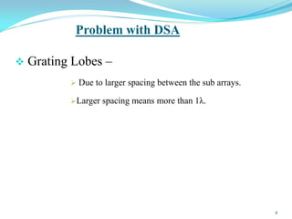
![Grating Lobes
Grating Lobes – just like side lobes that have same amplitude as main
beam and are unintended and creates interference
with main lobes, so it might limit our System
performance.[1,3]
Figure[3] :- Grating lobes produced by linear DSA (M=5, N=5, lx =7.5λ and dx=1.5λ.) element array.
.
5](https://image.slidesharecdn.com/suppressionofgratinglobes-150604085305-lva1-app6891/85/Suppression-of-grating-lobes-5-320.jpg)
![Principle of Pattern of Multiplication
The total field pattern of an array-is the
multiplication of the individual source pattern and
pattern of an array[2].
Symbolically-
……..(1)
Where- Ftotal – total field pattern of an array.
Fi(θ,Ф)—field pattern of individual source.
Fa(θ,Ф)--- field pattern of an array.
7
Ftotal = Fi(θ,Ф) Χ Fa(θ,Ф)](https://image.slidesharecdn.com/suppressionofgratinglobes-150604085305-lva1-app6891/85/Suppression-of-grating-lobes-7-320.jpg)
![Condition of Grating Lobes &
Null to be Occurred
We know about Array Factor of 2D Array[5] :-
Figure [2] :- shows the placement of sub arrays in DSA network.
Figure [3] :- shows the internal view of sub-arrays placed along X & Y axis.
Where :- Nx—number of element present in sub-arrays along x-axis.
Ny—number of element present in sub-arrays along y-axis.
dx—spacing b/w the elements present in sub-array X.
dy--spacing b/w the elements present in sub-array Y.
9](https://image.slidesharecdn.com/suppressionofgratinglobes-150604085305-lva1-app6891/85/Suppression-of-grating-lobes-9-320.jpg)
![contd….
The array factor can be expressed as[5] :-
AF=AFxAFy= 𝐴 𝑛 𝑒𝑗𝑛𝛽𝑙𝑥𝑆𝑖𝑛𝜃𝐶𝑜𝑠∅𝑀 𝑥
𝑛=1 𝐴 𝑚 𝑒𝑗𝑚𝛽𝑙𝑦𝑆𝑖𝑛𝜃𝐶𝑜𝑠∅𝑀 𝑦
𝑚=1 …..(4)
Where :- β - phase constant ; λ- wavelength.
Furthermore,if phases are introduces due to scan of beam in the direction
(θs,Фs) then[5]-
AF= 𝐴 𝑛
𝑀 𝑥
𝑛=1 ejnβlx{SinθCosФ-SinθsCosФs} 𝐴 𝑚
𝑀 𝑦
𝑚=1 ejmβly{sinθCosФ-SinθsCosФs}
…………(5)
Finally, if the array have the uniform excitation (An=Am=1),then Eq.(0) can
be expressed as a sum of geometric series as[5] :-
…………(6)
where :- ……….(7)
………(8)
10](https://image.slidesharecdn.com/suppressionofgratinglobes-150604085305-lva1-app6891/85/Suppression-of-grating-lobes-10-320.jpg)
![Contd……
the grating lobes of this equation can be predicted because it
have uniform spacing[5] :-
Grating lobes can occurs at the locations when ξx & ξy are the multiple of 2π .
……..(9a)
………(9b)
Where :- p , q = 0,1,2,3…….∞.
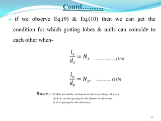
The location of nulls of this equation can occurs at[5] :-
…….(10a)
…..(10b)
where :- p , q are integer values start from 0,1,2,3…..
λ - wavelength ; Nx &Ny are number of element in sub arrays along x & y axis.
dx & dy are the spacing bw the element in sub arrays ; lx & ly spacing bw the sub-arrays.
11](https://image.slidesharecdn.com/suppressionofgratinglobes-150604085305-lva1-app6891/85/Suppression-of-grating-lobes-11-320.jpg)
![Contd…..
Figure[4] :- shows the grating lobes & null location for transmit array at f = 100MHz.
(Mx=My=5;Nx=Ny=5;dx=dy=0.5λ;lx=ly=5λ)
14](https://image.slidesharecdn.com/suppressionofgratinglobes-150604085305-lva1-app6891/85/Suppression-of-grating-lobes-14-320.jpg)
![Contd…..
Figure[5] :- shows the grating lobes & null location for receive array at f = 100MHz.
(Mx=My=10;Nx=Ny=10;dx=dy=0.5λ;lx=ly=5λ)
16](https://image.slidesharecdn.com/suppressionofgratinglobes-150604085305-lva1-app6891/85/Suppression-of-grating-lobes-16-320.jpg)
![Contd…..
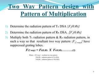
Final , two way pattern with pattern of multiplication is-
F(2 way) = Ft(θ,Ф) Χ Fr(θ,Ф)
• .
Table [A] :- shows the configuration data of both transmit & receive distributed sub arrays.
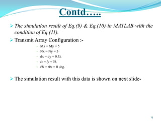
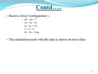
The simulation result with this data is shown on next slide-
17
Transmit Array Configuration Receive Array Configuration
Mx = My = 5 Mx = My = 10
Nx = Ny = 5 Nx = Ny = 10
dx = dy = 0.5λ dx = dy = 0.5λ
lx = ly = 5λ lx = ly = 5λ
Θs = Фs = 0 deg. Θs = Фs = 0 deg](https://image.slidesharecdn.com/suppressionofgratinglobes-150604085305-lva1-app6891/85/Suppression-of-grating-lobes-17-320.jpg)
![Contd…..
Figure[6] :- shows the overlap pattern of both transmit & receive array at f = 100MHz.
18](https://image.slidesharecdn.com/suppressionofgratinglobes-150604085305-lva1-app6891/85/Suppression-of-grating-lobes-18-320.jpg)
![[1] Mahafza R Basseam, Radar System Analysis and Design Using MATLAB, 3rd Edition, CHAPMAN & HALL/CRC New York
Washington, D.C.2000.
[2]Prasad .K.D, Introduction to Antenna and Wave Propagation,2nd Edition,pp.335-336,Satya Prakashan New Delhi India 2007
[3] Hovanessian A.S, Radar Systems Design and Analysis, 2nd Edition, pp. 271-290, ArTech House,INC, Norwood, MA, 1998.
[4] ]Ong.Chin.Siang,Jin Wang “ 2.4GHz Digital Phased Array Architectures For Distributed Sub Arrays" The Proceeding of the IEEE thirty
seventh South-eastern Symposium,march,20012.
[5] Jun Liu,zi-Jing Zhang ,Yun Yang “Implementation of Two way Pattern design in DSA”The IEEE Phased Array Radar LETTER,VOL 19
NO.10 August 2012.
[6] Jay Hyuk Choi “Distributed Sub Array Antennas for Multi Function Phased Array Radar”The IEEE International Conference on
Automation, Robotics and Application, held at Wellington,6-8 December 2011.
[7] Dr. Probir K. Bondyopadhyay, “The First Application of Distributed Sub Arrays” 2000 The Proceedings of IEEE International
Conference on Phased Array Systems & Technology, Dr. Michael Thorburn, ed., pp. 29-33, IEEE Operations Center, New Jersey, 2005.
[8] David K. Barton, Radar System Analysis, pp.83-89, 327-331, Artech House, Dedham, MA, 1979.
[9] Filippo Neri, Introduction to Electronic Defense Systems, 2nd Edition, pp. 156- 170, Artech House, Norwood, MA, 2009.
[10] Merrill I. Skolnik, Introduction to Radar Systems, 3rd Edition, pp. 210-238, McGr aw-Hill, New York, NY, 2005.
THANK-YOU
References
20](https://image.slidesharecdn.com/suppressionofgratinglobes-150604085305-lva1-app6891/85/Suppression-of-grating-lobes-20-320.jpg)


![3_Antenna Array [Modlue 4] (1).pdf](https://cdn.slidesharecdn.com/ss_thumbnails/3antennaarraymodlue41-220419112111-thumbnail.jpg?width=640&height=640&fit=bounds)