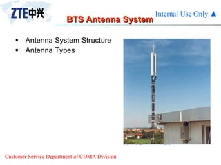
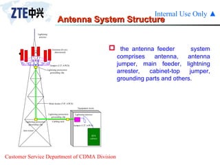
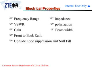
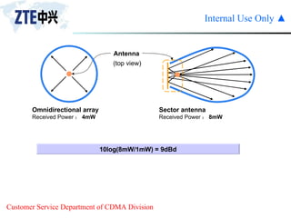
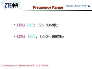
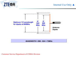
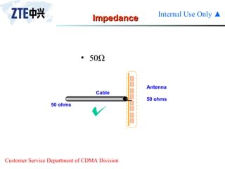
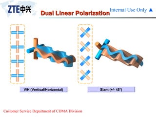
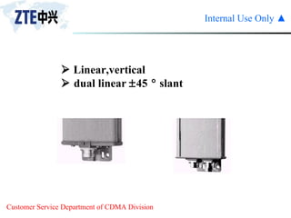
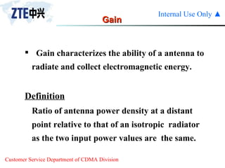
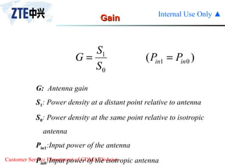
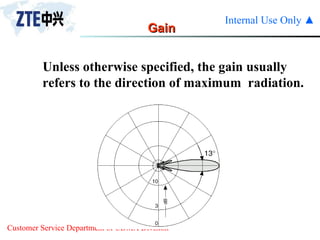
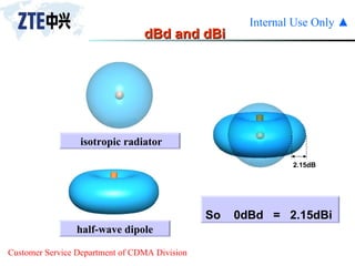
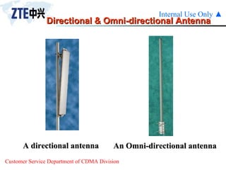
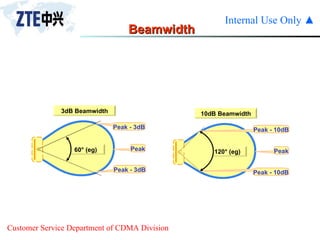
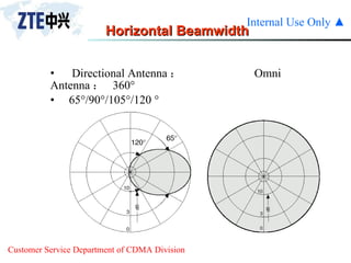
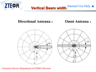
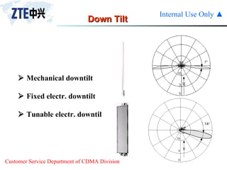
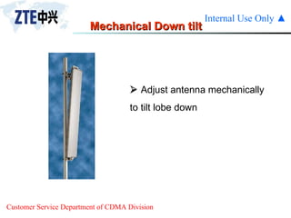
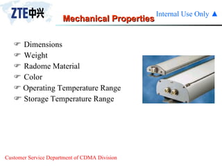
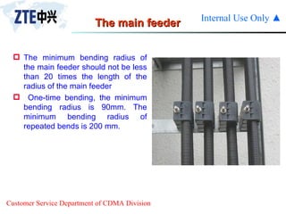
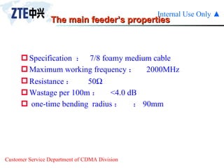
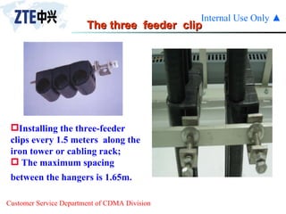
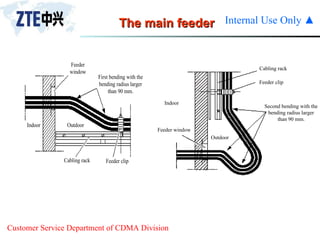
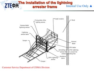
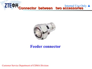
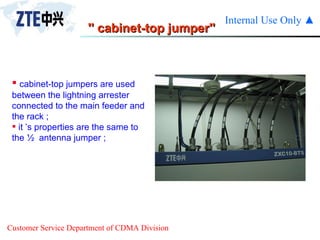
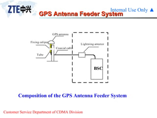
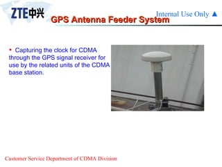
VIII.CDMA Antenna & Feeder  System
CDMA Antenna and Feeder System 3.1  Antenna Introduction 3.2  BTS Antenna System 3.3  Antenna Technical Parameters 3.3.1  Electrical Properties 3.3.2  Mechanical Properties 3.4  Antenna Development
Antenna Introduction Antenna is a structure or device used to  collect or radiate electromagnetic waves. Transmission  radiates electromagnetic energy into space Reception  collects electromagnetic energy from space
Antennas are widely used in our society Mobile Communication Satellite Communication  Wireless Radio Wireless Television Radar
In two-way communication, the same antenna can be used for transmission and reception the RF antenna System of the BTS GPS  Antenna System BSSB Antenna System
BTS Antenna System Antenna System Structure Antenna Types
Antenna System Structure the antenna feeder  system comprises antenna, antenna jumper, main feeder, lightning arrester, cabinet-top jumper, grounding parts and others.
Antenna Technical Parameters Usually, antenna has two kinds of  technical  parameters:    Electrical Properties    Mechanical Properties
   Frequency Range    Impedance    VSWR    polarization    Gain    Beam width     Front to Back Ratio    Up Side Lobe suppression and Null Fill Electrical Properties
Dipoles Wavelength 1/2 Wavelength 1/4 Wavelength 1/4 Wavelength 1/2 Wavelength Dipole   1800MHz  : 166 mm   900MHz  : 333mm
Gain  = 10log(4mW/1mW) = 6dBd one dipole  Received Power : 1mW Dipole array Received Power : 4 mW
10log(8mW/1mW) = 9dBd Sector antenna Received Power : 8mW Omnidirectional array Received Power : 4mW (top view) Antenna
Frequency Range CDMA  800 : 824-896MHz CDMA  1900 : 1850-1990MHz
BANDWIDTH  = 896 - 824 = 72MHz Optimum 1/2 wavelength for dipole at 860MHz at  896 MHz Antenna  Dipole at  824 MHz
Impedance 50  Cable  50 ohms Antenna 50 ohms
9.5 W Forward: 10W Reverse: 0.5W Return Loss :  10log(10/0.5) = 13dB VSWR (Voltage Standing Wave Ratio) VSWR 80  ohms 50 ohms
   VSWR  1.5  =(VSWR-1)/(VSWR+1)    RL=-20lg  
Polarization Vertical Horizontal Vertical Polarization: The electric field is vertical to the ground Horizontal Polarization: The electric field is parallel to the ground
+ 45degree slant - 45degree slant
Dual Linear Polarization V/H (Vertical/Horizontal) Slant (+/- 45°)
   Linear,vertical    dual linear   45   slant
Gain Definition Ratio of antenna power density at a distant  point relative to that of an isotropic  radiator as the two input power values are  the same. Gain characterizes the ability of a antenna to radiate and collect electromagnetic energy.
Gain G:   Antenna gain S 1 : P ower density at a distant point relative to antenna S 0 : Power density at the same point relative to isotropic  antenna P in1 :Input power of the antenna P in0 :Input power of the isotropic antenna
Gain Unless otherwise specified, the gain usually refers to the direction of maximum  radiation.
Antenna gain is usually expressed  in  dBi  or  dBd dBi  Gain relative to an isotropic antenna when the reference antenna is an isotropic antenna. dBd Gain relative to a half-wave dipole when the reference antenna is a half-wave dipole.  Gain
dBd and dBi half-wave dipole isotropic radiator So  0dBd  =  2.15dBi 2.15dB
A directional antenna An Omni-directional antenna Directional & Omni-directional Antenna
Beamwidth 120° (eg) Peak Peak - 10dB Peak - 10dB 10dB Beamwidth 60° (eg) Peak Peak - 3dB Peak - 3dB 3dB Beamwidth
Horizontal Beamwidth Directional Antenna :  Omni Antenna :  360° 65°/90°/105°/120 °
Vertical Beam width  Directional Antenna :  Omni Antenna :
Down Tilt    Mechanical downtilt    Fixed electr. downtilt    Tunable electr. downtilt
Mechanical Down tilt    Adjust antenna mechanically to tilt lobe down
Front to Back Ratio    Main lobe max. value to back lobe max. value ratio F/B  = 10 log(forward Power/Reversed Power)   typically  :  25dB Reversed Power Forward Power
Upper Side Lobes Suppression & Null Fill
Side lobes Upper Side Lobe  Suppression  ( dB)
Null Fill
Power Capacity    Continuous :25-1500watts    Typical: 250-500watts
1000mW ( 1W) 1mW 10log(1000mW/1mW) = 30dB Antenna Port Isolation
   For same frequency 、 dual frequency , isolation of  different port >30dB
Dimensions  Weight Radome Material Color    Operating Temperature Range Storage Temperature Range Mechanical Properties
Dimensions    Length  Width  Depth    Length  : related with vertical beamwidth 、 gain    Width : related with horizontal beamwidth    Depth : related with adoptive technology
Weight    Affect Transportation 、 construction
Radome Material    PVC, ABS,  fiberglass    Sun Protection 、 Ice Protection , Salt protection     Burning Blocking , Anti-aging etc.
Operating Temperature Range    Typical : -40°C  —  +70°C
Storage Temperature Range     Typical : -40°C  —  +70°C
Shipping Dimensions    Length  Width  Depth
Mast    Mast diameter: 45-90mm
Lightning Protection    DC  Grounded
Lightning rod  A grounded metal rod can prevent damage by conducting lightning to the ground ; It is placed on top of the structure
Lightning rod  The radio frequency antenna  must be installed within the 45   protection angle for arrester ;
Antenna Types A directional antenna An Omni-directional antenna
1/2 jumper ½ jumper is used between  cabinet-top and the main feeder cable , between the main feeder and antenna ;
1/2 jumper ’s properties Specification  :  ½  foamy medium cable; Maximum working frequency :  2000MHz; Resistance : 50  ; Wastage per 100m : <7.5 dB; One-time bending  radius :  32mm;
The main feeder The minimum bending radius of the main feeder should not be less than 20 times the length of the radius of the main feeder  One-time bending, the minimum bending radius is 90mm. The minimum bending radius of repeated bends is 200 mm.
The main feeder’s properties Specification  :  7/8 foamy medium cable Maximum working frequency :  2000MHz Resistance : 50  Wastage per 100m : <4.0 dB one-time bending  radius :  90mm
The three  feeder  clip Installing the three-feeder clips every 1.5 meters  along the iron tower or cabling rack;  The maximum spacing between the hangers is 1.65m.
The main feeder
Lightning arrester’s properties The feeder window is usually mounted on the wall outside the equipment room between the indoor and the outdoor cabling racks ;  The size of the feeder cable window provided by ZTE is 400 mm    400 mm. It is a four-hole window and 12 pieces of feeder cables can pass through it. A 300 mm    300 mm hole should be drilled on the wall for the installation of this feeder cable window.
Lightning arrester For the wide-band lightning arrester that need not be grounded separately, you may directly connect it in serial to the place between the main feeder and the indoor cabinet top jumper. During the installation, the lightning arrester and indoor equipment as the cabling rack should be insulated.
Lightning arrester’s properties Frequency :  1850-1990MHz Resistance : 50  Echo wastage : <-25dB The maximum attacking electronic current :   50kA The average manimum power : 3kw
Lightning Arrester For the lightning arrester that need be grounded, a lightning arrester frame should be provided.
The installation of the lightning arrester frame
Connector  between  two accessories Feeder connector
'' cabinet-top jumper'' cabinet-top jumpers are used between the lightning arrester connected to the main feeder and the rack ;  it ’s properties are the same to the ½  antenna jumper ;
GPS Antenna Feeder System  Composition of the GPS Antenna Feeder System
GPS Antenna Feeder System  Capturing the clock for CDMA through the GPS signal receiver for use by the related units of the CDMA base station.

02 cdma antenna and feeder system

  • 1.
    VIII.CDMA Antenna &Feeder System
  • 2.
    CDMA Antenna andFeeder System 3.1 Antenna Introduction 3.2 BTS Antenna System 3.3 Antenna Technical Parameters 3.3.1 Electrical Properties 3.3.2 Mechanical Properties 3.4 Antenna Development
  • 3.
    Antenna Introduction Antennais a structure or device used to collect or radiate electromagnetic waves. Transmission radiates electromagnetic energy into space Reception collects electromagnetic energy from space
  • 4.
    Antennas are widelyused in our society Mobile Communication Satellite Communication Wireless Radio Wireless Television Radar
  • 5.
    In two-way communication,the same antenna can be used for transmission and reception the RF antenna System of the BTS GPS Antenna System BSSB Antenna System
  • 6.
    BTS Antenna SystemAntenna System Structure Antenna Types
  • 7.
    Antenna System Structurethe antenna feeder system comprises antenna, antenna jumper, main feeder, lightning arrester, cabinet-top jumper, grounding parts and others.
  • 8.
    Antenna Technical ParametersUsually, antenna has two kinds of technical parameters:  Electrical Properties  Mechanical Properties
  • 9.
    Frequency Range  Impedance  VSWR  polarization  Gain  Beam width  Front to Back Ratio  Up Side Lobe suppression and Null Fill Electrical Properties
  • 10.
    Dipoles Wavelength 1/2Wavelength 1/4 Wavelength 1/4 Wavelength 1/2 Wavelength Dipole 1800MHz : 166 mm 900MHz : 333mm
  • 11.
    Gain =10log(4mW/1mW) = 6dBd one dipole Received Power : 1mW Dipole array Received Power : 4 mW
  • 12.
    10log(8mW/1mW) = 9dBdSector antenna Received Power : 8mW Omnidirectional array Received Power : 4mW (top view) Antenna
  • 13.
    Frequency Range CDMA 800 : 824-896MHz CDMA 1900 : 1850-1990MHz
  • 14.
    BANDWIDTH =896 - 824 = 72MHz Optimum 1/2 wavelength for dipole at 860MHz at 896 MHz Antenna Dipole at 824 MHz
  • 15.
    Impedance 50 Cable 50 ohms Antenna 50 ohms
  • 16.
    9.5 W Forward:10W Reverse: 0.5W Return Loss : 10log(10/0.5) = 13dB VSWR (Voltage Standing Wave Ratio) VSWR 80 ohms 50 ohms
  • 17.
    VSWR  1.5  =(VSWR-1)/(VSWR+1)  RL=-20lg 
  • 18.
    Polarization Vertical HorizontalVertical Polarization: The electric field is vertical to the ground Horizontal Polarization: The electric field is parallel to the ground
  • 19.
    + 45degree slant- 45degree slant
  • 20.
    Dual Linear PolarizationV/H (Vertical/Horizontal) Slant (+/- 45°)
  • 21.
    Linear,vertical  dual linear  45  slant
  • 22.
    Gain Definition Ratioof antenna power density at a distant point relative to that of an isotropic radiator as the two input power values are the same. Gain characterizes the ability of a antenna to radiate and collect electromagnetic energy.
  • 23.
    Gain G: Antenna gain S 1 : P ower density at a distant point relative to antenna S 0 : Power density at the same point relative to isotropic antenna P in1 :Input power of the antenna P in0 :Input power of the isotropic antenna
  • 24.
    Gain Unless otherwisespecified, the gain usually refers to the direction of maximum radiation.
  • 25.
    Antenna gain isusually expressed in dBi or dBd dBi Gain relative to an isotropic antenna when the reference antenna is an isotropic antenna. dBd Gain relative to a half-wave dipole when the reference antenna is a half-wave dipole. Gain
  • 26.
    dBd and dBihalf-wave dipole isotropic radiator So 0dBd = 2.15dBi 2.15dB
  • 27.
    A directional antennaAn Omni-directional antenna Directional & Omni-directional Antenna
  • 28.
    Beamwidth 120° (eg)Peak Peak - 10dB Peak - 10dB 10dB Beamwidth 60° (eg) Peak Peak - 3dB Peak - 3dB 3dB Beamwidth
  • 29.
    Horizontal Beamwidth DirectionalAntenna : Omni Antenna : 360° 65°/90°/105°/120 °
  • 30.
    Vertical Beam width Directional Antenna : Omni Antenna :
  • 31.
    Down Tilt  Mechanical downtilt  Fixed electr. downtilt  Tunable electr. downtilt
  • 32.
    Mechanical Down tilt Adjust antenna mechanically to tilt lobe down
  • 33.
    Front to BackRatio  Main lobe max. value to back lobe max. value ratio F/B = 10 log(forward Power/Reversed Power) typically : 25dB Reversed Power Forward Power
  • 34.
    Upper Side LobesSuppression & Null Fill
  • 35.
    Side lobes UpperSide Lobe Suppression ( dB)
  • 36.
  • 37.
    Power Capacity  Continuous :25-1500watts  Typical: 250-500watts
  • 38.
    1000mW ( 1W)1mW 10log(1000mW/1mW) = 30dB Antenna Port Isolation
  • 39.
    For same frequency 、 dual frequency , isolation of different port >30dB
  • 40.
    Dimensions WeightRadome Material Color  Operating Temperature Range Storage Temperature Range Mechanical Properties
  • 41.
    Dimensions  Length  Width  Depth  Length : related with vertical beamwidth 、 gain  Width : related with horizontal beamwidth  Depth : related with adoptive technology
  • 42.
    Weight  Affect Transportation 、 construction
  • 43.
    Radome Material  PVC, ABS, fiberglass  Sun Protection 、 Ice Protection , Salt protection  Burning Blocking , Anti-aging etc.
  • 44.
    Operating Temperature Range Typical : -40°C — +70°C
  • 45.
    Storage Temperature Range  Typical : -40°C — +70°C
  • 46.
    Shipping Dimensions  Length  Width  Depth
  • 47.
    Mast  Mast diameter: 45-90mm
  • 48.
  • 49.
    Lightning rod A grounded metal rod can prevent damage by conducting lightning to the ground ; It is placed on top of the structure
  • 50.
    Lightning rod The radio frequency antenna must be installed within the 45  protection angle for arrester ;
  • 51.
    Antenna Types Adirectional antenna An Omni-directional antenna
  • 52.
    1/2 jumper ½jumper is used between cabinet-top and the main feeder cable , between the main feeder and antenna ;
  • 53.
    1/2 jumper ’sproperties Specification : ½ foamy medium cable; Maximum working frequency : 2000MHz; Resistance : 50  ; Wastage per 100m : <7.5 dB; One-time bending radius :  32mm;
  • 54.
    The main feederThe minimum bending radius of the main feeder should not be less than 20 times the length of the radius of the main feeder One-time bending, the minimum bending radius is 90mm. The minimum bending radius of repeated bends is 200 mm.
  • 55.
    The main feeder’sproperties Specification : 7/8 foamy medium cable Maximum working frequency : 2000MHz Resistance : 50  Wastage per 100m : <4.0 dB one-time bending radius :  90mm
  • 56.
    The three feeder clip Installing the three-feeder clips every 1.5 meters along the iron tower or cabling rack; The maximum spacing between the hangers is 1.65m.
  • 57.
  • 58.
    Lightning arrester’s propertiesThe feeder window is usually mounted on the wall outside the equipment room between the indoor and the outdoor cabling racks ; The size of the feeder cable window provided by ZTE is 400 mm  400 mm. It is a four-hole window and 12 pieces of feeder cables can pass through it. A 300 mm  300 mm hole should be drilled on the wall for the installation of this feeder cable window.
  • 59.
    Lightning arrester Forthe wide-band lightning arrester that need not be grounded separately, you may directly connect it in serial to the place between the main feeder and the indoor cabinet top jumper. During the installation, the lightning arrester and indoor equipment as the cabling rack should be insulated.
  • 60.
    Lightning arrester’s propertiesFrequency : 1850-1990MHz Resistance : 50  Echo wastage : <-25dB The maximum attacking electronic current :  50kA The average manimum power : 3kw
  • 61.
    Lightning Arrester Forthe lightning arrester that need be grounded, a lightning arrester frame should be provided.
  • 62.
    The installation ofthe lightning arrester frame
  • 63.
    Connector between two accessories Feeder connector
  • 64.
    '' cabinet-top jumper''cabinet-top jumpers are used between the lightning arrester connected to the main feeder and the rack ; it ’s properties are the same to the ½ antenna jumper ;
  • 65.
    GPS Antenna FeederSystem Composition of the GPS Antenna Feeder System
  • 66.
    GPS Antenna FeederSystem Capturing the clock for CDMA through the GPS signal receiver for use by the related units of the CDMA base station.