Downloaded 700 times

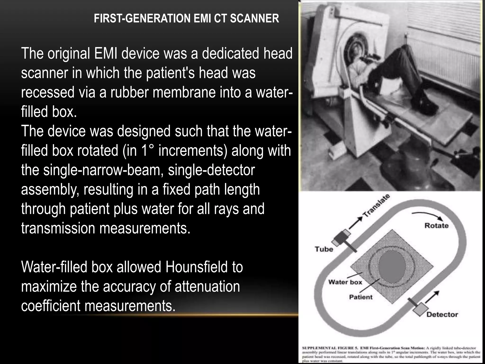


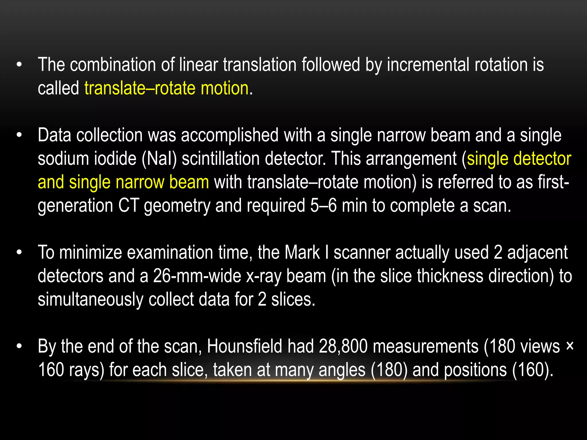


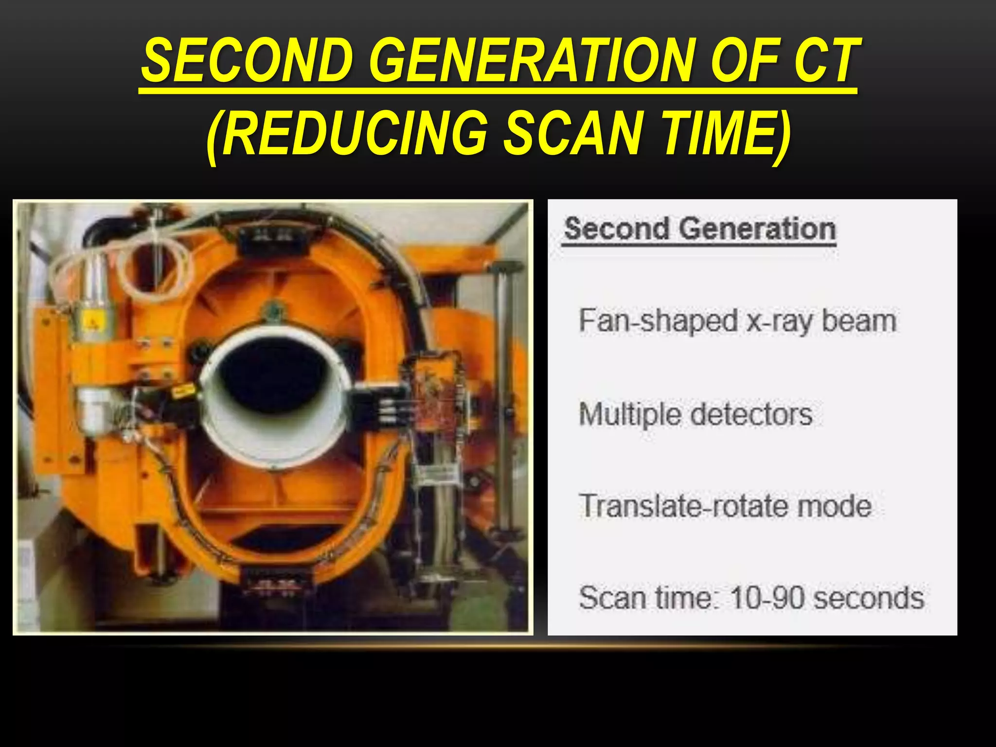


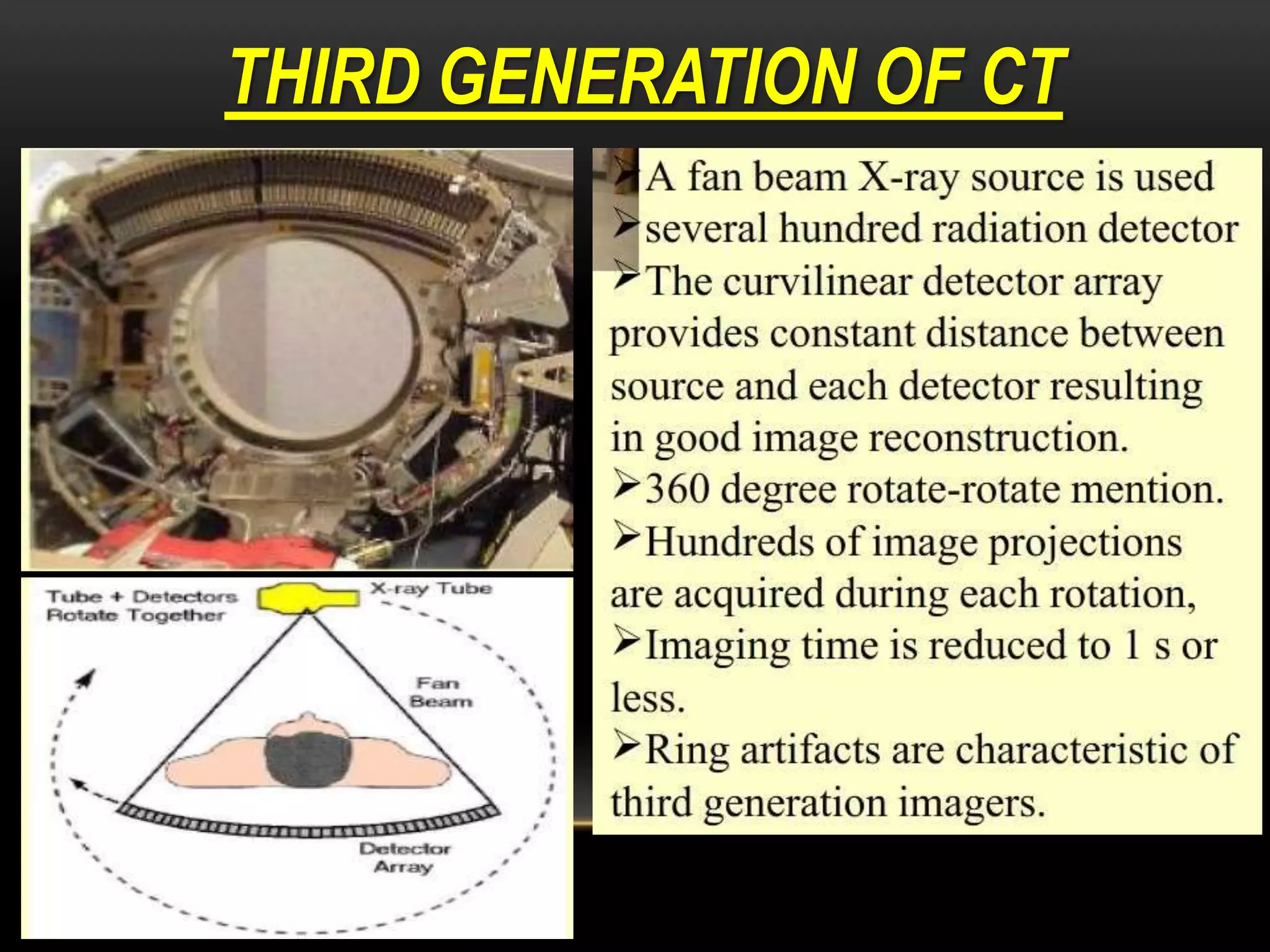


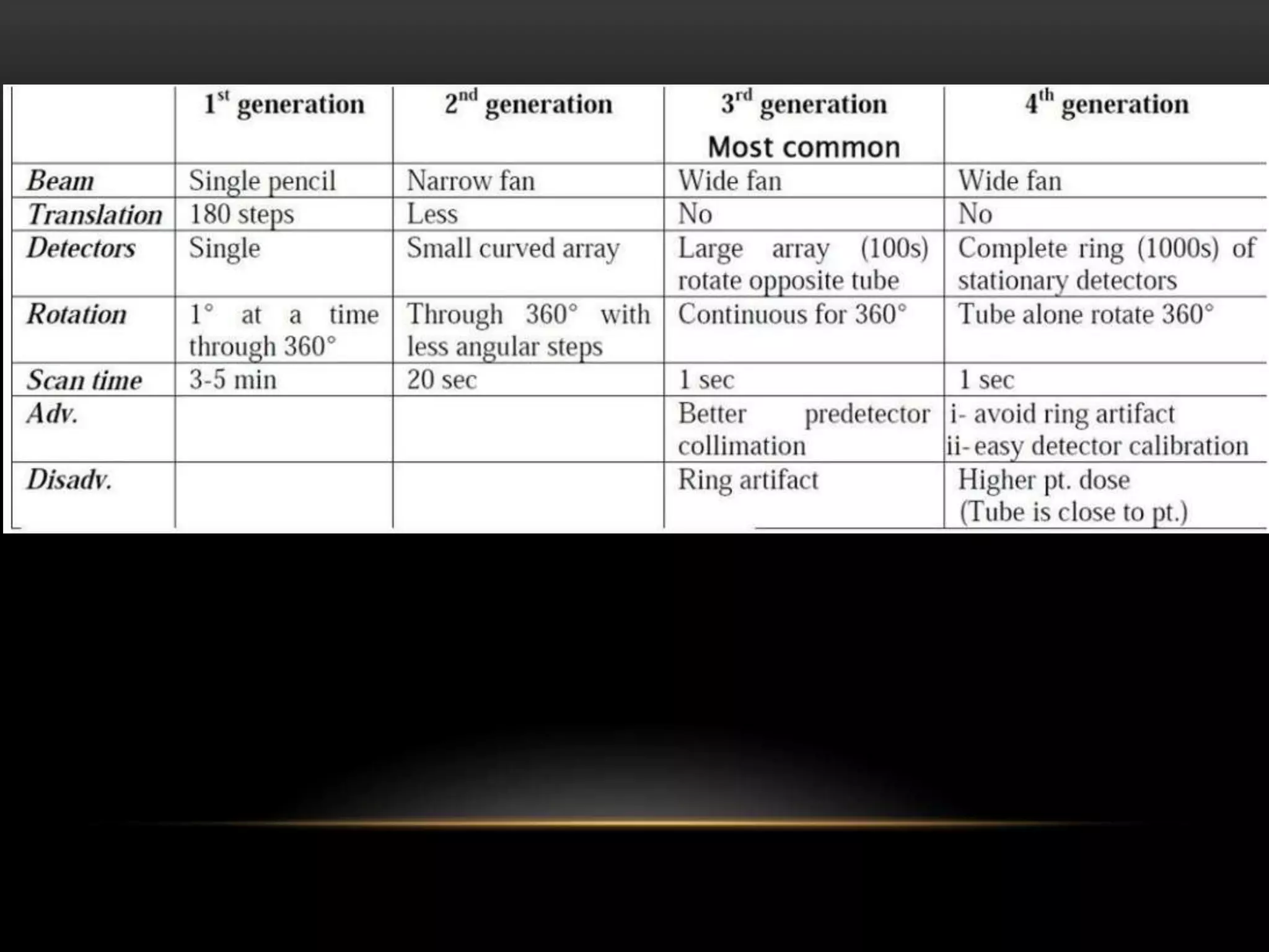


1. The first generation of CT used a single narrow x-ray beam and detector that rotated around the patient in a translate-rotate motion. It took 5-6 minutes to complete a scan. 2. The second generation used multiple narrow beams and detectors, reducing scan time by a factor equal to the number of detectors by collecting multiple views simultaneously. Scan times were reduced to 20 seconds. 3. The third generation eliminated translation motion by using a fan-beam of x-rays and multiple stationary detectors arranged in a ring. Only rotational motion was needed, simplifying the mechanics. This further reduced scan times.


