Downloaded 225 times
![Name of Institution REVERSE SHIFT
PREVENTION
21
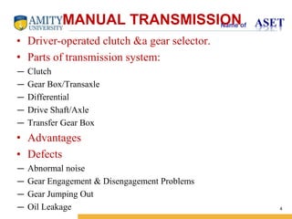
The cubic projection on the gear shift and select
lever is blocked by the projection of reverse shift
limit yoke when gear shift control lever is
shifted from 5th position to reverse position.
1. Gear shift and select lever
2. Reverse shift limit yoke
[A] : 5th
[B] : Reverse
[C] : 4th
As cubic projection of gear shift and select
lever pushes the reverse shift limit yoke, the
yoke rotates and pushes the cubic projection
of the lever toward the neutral position.
Gear is shifted into 4th position if gear shift
and select lever is still pushed toward
reverse position. Reverse shift limit yoke
returns to original position by spring force.](https://image.slidesharecdn.com/summerinternppt-131027013222-phpapp01d-141013151011-conversion-gate02/85/Transmission-In-Maruti-cars-21-320.jpg)
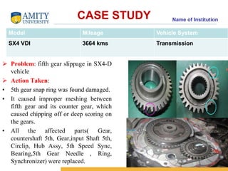


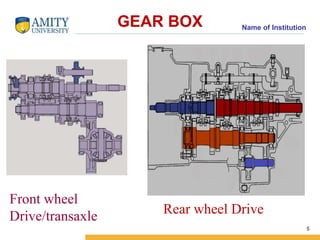
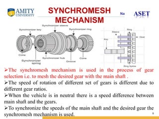
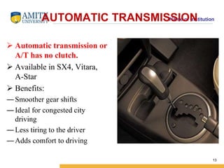
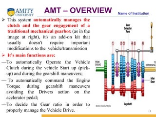
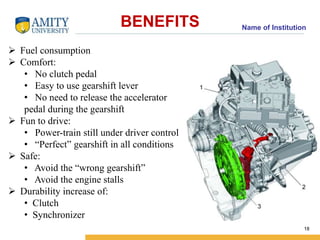
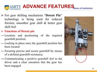
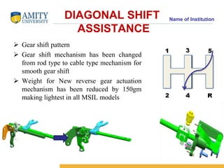
This document summarizes different types of vehicle transmissions, including manual, automatic, and auto-manual transmissions. It describes the key components of a manual transmission like the clutch, gearbox, differential, and drive shaft. Automatic transmissions are introduced as having no clutch and providing smoother gear shifts. An auto-manual transmission is described as automatically operating the clutch and commanding engine torque for gear shifts. Advanced features like detent pins for smoother gear changes are also summarized. The document concludes with a case study of repairing a fifth gear slippage issue in an SX4 vehicle.


![Engine management system[ EMS ] or Engine Control Unit [ ECU ]](https://cdn.slidesharecdn.com/ss_thumbnails/enginemanagementsystem-170920182131-thumbnail.jpg?width=640&height=640&fit=bounds)


