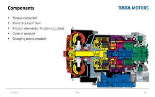
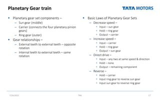
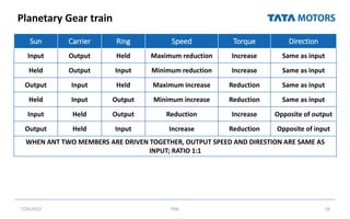
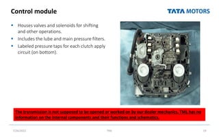
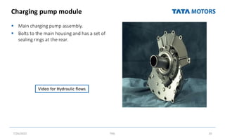
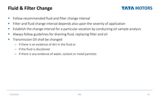
This document provides an overview of a training module on transmission and clutch systems. The module objectives are to perform basic checks, maintenance, dismantling and assembly of transmissions and clutches. The agenda covers Allison automatic transmissions, ZF manual gearboxes, and clutch system overhauling. Preventive maintenance tips are provided for transmissions, including fluid level checks, fluid and filter changes. Components and operation of Allison transmissions are explained. Practical exercises include identifying gearbox components, checking fluid levels, and removing/refitting a gearbox.


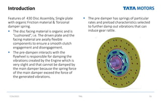
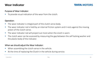
![Clutch Assembly
Remove the two guide studs and crew in
the remaining 2 mounting bolts
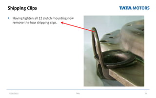
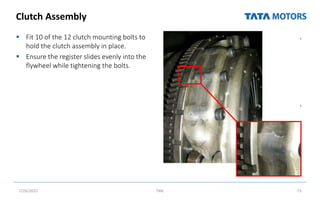
Tighten the 12 clutch mounting bolts in
two stages to the correct torque setting
– 22lb/ft [30nm] : Fist Stage
– 43lb/ft [58nm] : Second Stage
The sequence is shown in the image
7/26/2022 TML 74](https://image.slidesharecdn.com/clutchtransmissionsystem-220726075107-4a5d364e/85/Clutch-Transmission-System-pptx-74-320.jpg)