Downloaded 1,291 times
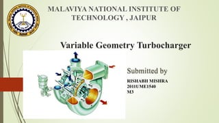
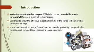


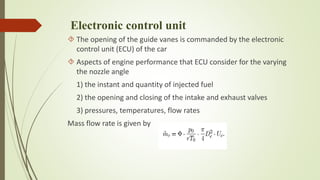


The document discusses variable geometry turbochargers (VGTs), which adjust the aspect ratio of the turbocharger to optimize engine performance across varying conditions. It covers the history, working principles, benefits, and design considerations of VGTs, including the role of the electronic control unit in managing nozzle angles. The conclusion highlights the VGT's ability to enhance intake air mass flow, reduce pumping losses, and improve overall engine efficiency.


