Downloaded 162 times


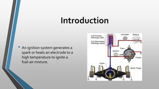


The document discusses various sensors used in modern vehicle ignition systems. It describes common sensors like oxygen sensors, coolant temperature sensors, crankshaft position sensors, throttle position sensors, manifold absolute pressure sensors, and knock sensors. It explains how each sensor works and the important role it plays in engine management and emissions control. Modern ignition systems rely on input from multiple sensors to precisely control ignition timing, fuel delivery, and emissions equipment.