1. Site Exploration
3
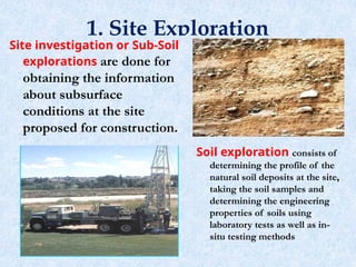
Siteinvestigation or Sub-Soil
explorations are done for
obtaining the information
about subsurface
conditions at the site
proposed for construction.
Soil exploration consists of
determining the profile of the
natural soil deposits at the site,
taking the soil samples and
determining the engineering
properties of soils using
laboratory tests as well as in-
situ testing methods
4.
1.1. Purpose ofsoil exploration
The primary objective is to analyze the nature of
the soil in all aspects, basically is to find out
strength characteristics of the sub-soil over which
the structure has to be built.
Soil exploration includes:
Selection of alternative construction sites or the
choice of the most economical sites,
Selection of alternative types or depth of
foundation,
Selection of alternative methods of construction,
Evaluation of the safety of existing structure,
Location and selection of construction materials.
4
5.
The soil explorationshould provide the
following data:
Soil parameters and properties of different
layers (e.g. for classification, bearing
capacity or settlement calculation),
Thickness of soil layers and depth to
bedrock (stratification of soil),
Location of ground water level and
important groundwater related issues,
Special problems and concerns.
5
6.
1.2. Phases ofSite Exploration (Ground
Investigation)
• The planning of a program for soil exploration
depends upon:
– The nature of sub-soil
– The type of structure
– The importance of structure
• The actual planning of a subsurface exploration
program includes some or all of the following
steps:
i. Desk-study:
Assembly of all available information on type and use of
the structure, and also of the general topographic and
geological character of the site.
6
7.
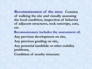
ii. Reconnaissance ofthe area: Consists
of walking the site and visually assessing
the local condition, inspection of behavior
of adjacent structures, rock outcrops, cuts,
etc.
Reconnaissance includes the assessment of;
• Any previous development on site,
• Any previous grading on site,
• Any potential landslide or other stability
problems,
• Condition of nearby structure
7
8.
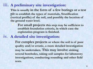
iii. A preliminarysite investigation:
This is usually in the form of a few borings or a test
pit to establish the types of materials, Stratification
(vertical profile) of the soil, and possibly the location of
the ground water level.
For small projects this step may be sufficient to
establish foundation criteria, in which case the
exploration program is finished.
iv. A detailed site investigation:
For complex projects or where the soil is of poor
quality and/or erratic, a more detailed investigation
may be undertaken. This may involve sinking
several boreholes, taking soil samples for laboratory
investigations, conducting sounding and other field
tests.
8
9.
1.3. Methods ofSite Exploration (Ground
Investigation)
Methods of determining the stratification and
engineering characteristics of sub-surface are
Test pits
Boring and sampling
Field tests
Geophysical methods
Laboratory tests
Test Pits
• The simplest and cheapest method of shallow soil
exploration is to sink test pit to depths of 3 to 4 m.
• Test pits enable the in-situ soil conditions to be examined
visually.
• It is relatively easy to obtain disturbed or undisturbed soil
samples:
9
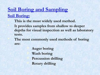
Soil Boring andSampling
Soil Boring:
• This is the most widely used method.
• It provides samples from shallow to deeper
depths for visual inspection as well as laboratory
tests.
• The most commonly used methods of boring
are:
Auger boring
Wash boring
Percussion drilling
Rotary drilling
11
12.
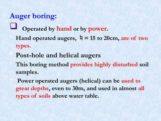
Auger boring:
Operatedby hand or by power.
• Hand operated augers, = 15 to 20cm, are of two
types.
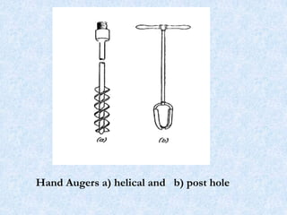
• Post-hole and helical augers
• This boring method provides highly disturbed soil
samples.
• Power operated augers (helical) can be used to
great depths, even to 30m, and used in almost all
types of soils above water table.
12
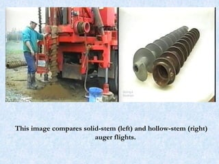
This image comparessolid-stem (left) and hollow-stem (right)
auger flights.
14
15.
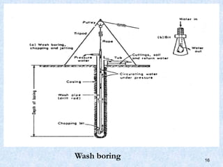
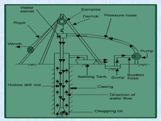
Wash boring:
Power operated.
Holeis advanced by chopping, twisting action of a light
chopping bit and jetting action of drilling fluid, usually
water, under pressure.
Loosened soil particles rise as suspended particles
through the annular space between casing and drill rod.
This method best suits in sandy and clayey soils and not
in very hard soil strata (i.e. boulders) and rocks.
Depth of boring could be up to 60m or more.
Changes in soil strata are indicated by changes in the
rate of progress of boring, examination of out coming slurry
and cutting in the slurry.
Undisturbed samples whenever needed can be obtained by
use of proper samplers.
15
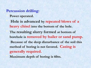
Percussion drilling:
• Poweroperated.
• Hole is advanced by repeated blows of a
heavy chisel into the bottom of the hole.
• The resulting slurry formed at bottom of
borehole is removed by bailer or sand pump.
• Because of the deep disturbance of the soil this
method of boring is not favored. Casing is
generally required.
• Maximum depth of boring is 60m.
19
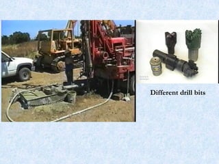
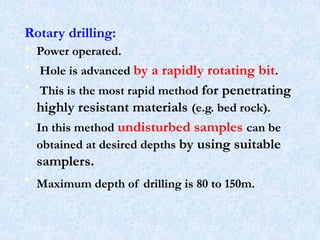
Rotary drilling:
• Poweroperated.
• Hole is advanced by a rapidly rotating bit.
• This is the most rapid method for penetrating
highly resistant materials (e.g. bed rock).
• In this method undisturbed samples can be
obtained at desired depths by using suitable
samplers.
• Maximum depth of drilling is 80 to 150m.
21
Drilling in soilsprone to caving or squeezing
• Open hole methods encounter problems in soils
prone to caving (i.e., the sides of the boring
fall in) or squeezing (the soil moves inwards,
reducing the boring diameter).
• Caving is most likely in loose sands and
gravels, especially below the groundwater table,
while squeezing is likely in soft saturated silts
and clays.
• In such cases, it becomes necessary to provide
some type of lateral support inside the hole during
drilling. 23
24.
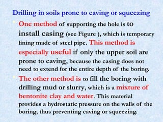
Drilling in soilsprone to caving or squeezing
• One method of supporting the hole is to
install casing (see Figure ), which is temporary
lining made of steel pipe. This method is
especially useful if only the upper soil are
prone to caving, because the casing does not
need to extend for the entire depth of the boring.
• The other method is to fill the boring with
drilling mud or slurry, which is a mixture of
bentonite clay and water. This material
provides a hydrostatic pressure on the walls of the
boring, thus preventing caving or squeezing.
24
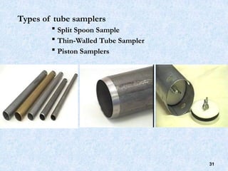
Soil Sampling
• Laboratorytest results are mainly dependent on
the quality of soil samples.
• There are two main types of soil samples which
can be recovered from bore holes or trial pits.
Disturbed and
Undisturbed samples
26
Disturbed Samples
• Theseare samples where the structure of the
natural soil has been disturbed to a
considerable degree by the action of the
boring tools or excavation equipment.
• However, these samples represent the
composition and the mineral content
of the soil.
• Disturbed samples are satisfactory for
performing classification tests such as,
sieve analysis, Atterberg limits etc.
28
29.
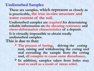
Undisturbed Samples
• Theseare samples, which represent as closely as
is practicable, the true in-situ structure and
water content of the soil.
• Undisturbed samples are required for determining
reliable information on the shearing resistance and
stress-deformation characteristics of a deposit.
• It is virtually impossible to obtain totally
undisturbed samples.
This is due to that:
The process of boring, driving the coring
tool, raising and withdrawing the coring tool
and extruding the sample from the coring
tool, all conspire to cause some disturbance.
In addition, samples taken from holes may
tend to swell as a result of stress relief.
29
30.
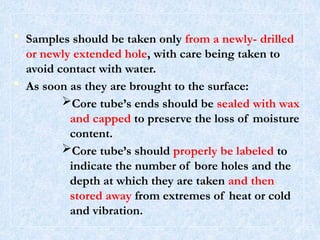
• Samples shouldbe taken only from a newly- drilled
or newly extended hole, with care being taken to
avoid contact with water.
• As soon as they are brought to the surface:
Core tube’s ends should be sealed with wax
and capped to preserve the loss of moisture
content.
Core tube’s should properly be labeled to
indicate the number of bore holes and the
depth at which they are taken and then
stored away from extremes of heat or cold
and vibration.
30
Field [in-situ] tests
•These tests are valuable means of determining the
relative densities; shear strengths and bearing
capacities of soils directly without disturbing effects
of boring and sampling.
• The most commonly used field tests are:
Penetration or sounding tests
Vane shear test
Plate loading test
Pile loading test
32
33.
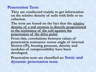
Penetration Tests
• Theyare conducted mainly to get information
on the relative density of soils with little or no
cohesion.
• The tests are based on the fact that the relative
density of a soil stratum is directly proportional
to the resistance of the soil against the
penetration of the drive point.
• From this, correlations between values of
penetration resistance versus angle of internal
friction (Φ), bearing pressure, density and
modulus of compressibility have been
developed.
• Penetration tests are classified as: Static and
dynamic penetration tests.
33
34.
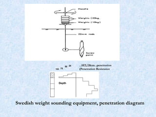
Static Penetration Tests
1)Swedish Weight Sounding Test:
• This method of testing is widely used in
Scandinavia and here in Ethiopia.
• The depth of penetration is measured for each
loading after which the number of half-turns is
counted by 100kg (1 KN) load; the penetration
depth is then measured after 25 half-turns.
• If the penetration after 25 half-turns is less
than 5cm the rod is unloaded and driven down by
a 5 to 6kg hammer.
34
• The correlationbetween density of frictional soils and
consistency (relative strength) of cohesive soils and ht/m
(half-turns per meter) are as given below.
Frictional Soils Density (kN/m3
)
Very loose <50ht/m 11-16
Loose 50 -150ht/m 14.5 - 18.5
Medium 150 - 300ht/m 17.5 - 21
Dense 300 - 500ht/m 17.5 - 22.5
Very dense > 500ht/m 21 – 24
Cohesive Soils Density (kN/m3
)
Soft 0 ht/m 16 –19
Firm 0 – 100 ht/m 17.5 – 21
Stiff 100-200 ht/m
Very stiff 200 - 500 ht/m 19 – 22.5
Hard >500 ht/m
36
37.
2. Static ConePenetration Test (Dutch Cone
Penetrometer Test):
• This method is widely used in Europe.
• The test consists of a cone (apex angle 600
, overall
diameter 35.7mm, end area 10cm2
, rods (⅝” ),
casing pipe ( ¾”).
• The rod is pushed hydraulically into the ground at a
rate of 10mm/sec.
• The pressure exerted on the rod is measured with a
proving ring, manometer or a strain gauge.
• The cone is 1st
pushed into the ground. The force
required to push the cone 20cm into the soil is
recorded. (Point Resistance)
• The casing pipe is then advanced to join the cone.
The force required to push the pipe is also recorded.
(Total Resistance)
• The readings thus taken are plotted against depth.
37
Correlation between Cone(Point) Resistance and
Relative Density of Frictional Soils
Relative Density Point Resistance (kN/m2
)
Very loose soil < 2500
Medium dense 5000 – 10,000
Dense 10,000 – 15,000
Very dense > 15,000
According to Meyerhof:
N = ¼ (Ckd)
where: N = Standard penetration number
Ckd = Static Cone resistance (kg/cm2
)
For sand, modulus of compressibility (ES) can be estimated
from cone resistance from the following relationship.
ES =3/2(Ckd) 39
40.
Dynamic Penetration Tests
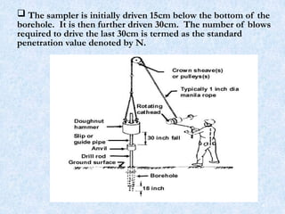
1)Standard Penetration Test (SPT):
• This is the most common of the field tests and
measures the resistance of the soil to dynamic
penetration by a 50mm diameter split spoon
sampler which is driven into the soil at the bottom
of a borehole (sometimes cased).
• The sampler is attached to drill rods and the
dynamic driving force is a 63.5kg mass falling
through a height of 76cm onto the top of the rods.
40
41.
41
The sampleris initially driven 15cm below the bottom of the
borehole. It is then further driven 30cm. The number of blows
required to drive the last 30cm is termed as the standard
penetration value denoted by N.
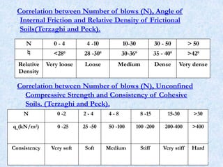
Correlation between Numberof blows (N), Angle of
Internal Friction and Relative Density of Frictional
Soils(Terzaghi and Peck).
N 0 - 4 4 -10 10-30 30 - 50 > 50
<280
28 -300
30-360
35 - 400
>420
Relative
Density
Very loose Loose Medium Dense Very dense
Correlation between Number of blows (N), Unconfined
Compressive Strength and Consistency of Cohesive
Soils. (Terzaghi and Peck).
N 0 -2 2 - 4 4 - 8 8 -15 15-30 >30
qu
(kN/m2
) 0 -25 25 -50 50 -100 100 -200 200-400 >400
Consistency Very soft Soft Medium Stiff Very stiff Hard
43
44.
• The relationshipbetween and Dr may be
expressed approximately by the following
equation (Meyerhof):
For granular soil, containing more than 5
percent fine sand and silt.
0
=25+0.15Dr
• For granular soil, containing less than 5
percent fine sand and silt. In the equations Dr
is expressed in percent.
0
=30+0.15Dr
44
45.
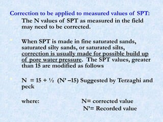
Correction to beapplied to measured values of SPT:
• The N values of SPT as measured in the field
may need to be corrected.
• When SPT is made in fine saturated sands,
saturated silty sands, or saturated silts,
correction is usually made for possible build up
of pore water pressure. The SPT values, greater
than 15 are modified as follows
• N = 15 + ½ (N’ –15) Suggested by Terzaghi and
peck
where: N= corrected value
N’= Recorded value
45
46.
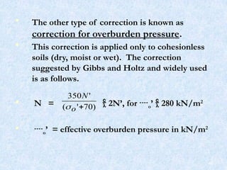
• The othertype of correction is known as
correction for overburden pressure.
• This correction is applied only to cohesionless
soils (dry, moist or wet). The correction
suggested by Gibbs and Holtz and widely used
is as follows.
• N = 2N’, for o’ 280 kN/m2
• o’ = effective overburden pressure in kN/m2
)
70
'
(
'
350
o
N
46
47.
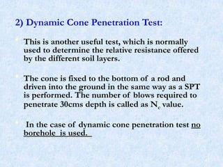
2) Dynamic ConePenetration Test:
• This is another useful test, which is normally
used to determine the relative resistance offered
by the different soil layers.
• The cone is fixed to the bottom of a rod and
driven into the ground in the same way as a SPT
is performed. The number of blows required to
penetrate 30cms depth is called as Nc value.
• In the case of dynamic cone penetration test no
borehole is used.
47
48.
• Experiments carriedout indicate that beyond about
6m depth, frictional resistance on the rod increases
which gives erroneous results for Nc value. The
maximum depth suggested for this test is about 6
m.
• If the test has to be conducted beyond 6 m depth,
one has to use drilling mud (bentonite slurry) under
pressure forced through the pipe and the cone.
• The mud solution coming out of the cone rises
above along the drill rod eliminating thereby the
frictional resistance offered by the soil for
penetration.
• The former method is called as dry method and the
latter wet method.
48
49.
• To judgethe consistency of soil from Nc values, the
general practice is to convert Nc to N values of SPT:
Nc = N/C
Where:
N = blow count for SPT
Nc = blow count for dynamic cone
C = Constant, lies between 0.8 and 1.2 when
bentonite is used.
Nc = 1.5N for depths up to 3m
Nc = 1.75N for depths between 3m and 6m
Nc Values need to be corrected for overburden
pressure in cohesionless soils like SPT
49
50.
Vane Shear Test
•It is used to determine the undrained shear
strength of soft clays soils.
• The apparatus consists of a vertical steel rod
having four thin stainless steel blades (vanes)
fixed at its bottom ends.
• Vane head (torsion head), complete with pointer,
stop pin, circumferential graduated scale,
calibrated torsion spring.
50
• In mostcases a hole is drilled to the desired
depth, where the vane shear test is planned to be
performed and the vane is carefully pushed into
the soil.
• A torque necessary to shear the cylinder of soil
defined by the blades of the vane is applied by
rotating the arm of the apparatus with a
constant speed of 0.5 degree/sec.
• The maximum torque is then measured from
which the shearing strength is determined.
• From the measured maximum torque one may
estimate the shearing resistance of the tested
clay from the following formula.
53
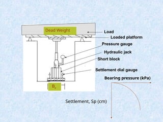
Plate Loading Test
•In this test a gradually increasing static load is applied to
the soil through a steel plate, and readings of the
settlement and applied load are recorded, from which a
relationship between bearing pressure and settlement for
the soil can be obtained.
The test procedure:
1. Pit for the test must be at least 5 times the size of the
plate.
2. The plate should be properly placed in the soil. In the
case of cohesionless soil (to prevent early displacement of
soil under the edges of the plate), the plate must be
positioned in cast in-situ concrete.
3. Loading platform should be properly erected.
55
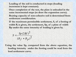
4. Loading ofthe soil is conducted in steps (loading
increment is kept constant).
5. Once completion of the test, the plate is unloaded in the
same incremental steps (to draw the expansion curve).
• Bearing capacity of non-cohesive soil is determined from
settlement consideration.
• If the maximum permissible settlement, S, of a footing of
width Bf is given, the settlement, Sp, of a plate of width
Bp under the same intensity of loading is given by.
2
)
(
2
)
2
(
p
B
f
B
Bf
Sp
S
Using the value Sp, computed from the above equation, the
loading intensity under the footing could be read from the
load settlement curve.
58
59.
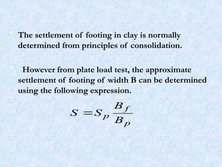
• The settlementof footing in clay is normally
determined from principles of consolidation.
• However from plate load test, the approximate
settlement of footing of width B can be determined
using the following expression.
p
f
p
B
B
S
S
59
60.
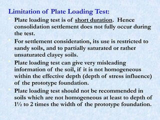
Limitation of PlateLoading Test:
• Plate loading test is of short duration. Hence
consolidation settlement does not fully occur during
the test.
• For settlement consideration, its use is restricted to
sandy soils, and to partially saturated or rather
unsaturated clayey soils.
• Plate loading test can give very misleading
information of the soil, if it is not homogeneous
within the effective depth (depth of stress influence)
of the prototype foundation.
• Plate loading test should not be recommended in
soils which are not homogeneous at least to depth of
1½ to 2 times the width of the prototype foundation.
60
61.
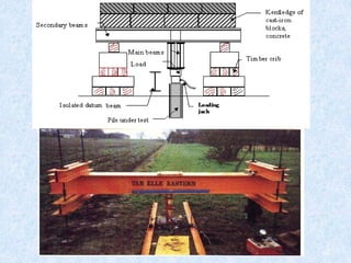
Pile Loading Test:
•This is the most reliable means of
determining the load carrying capacity of
a pile.
• The load arrangement and testing
procedure are more or less similar to the
plate-loading test.
• From the results of this test, the allowable
bearing capacity and load-settlement
relationship of a group of friction piles can
be estimated.
61
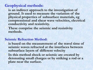
Geophysical methods:
• isan indirect approach to the investigation of
ground. It used to measure the variation of the
physical properties of subsurface materials, eg
compressional and shear wave velocities, electrical
conductivity and resistivity.
• These comprise the seismic and resistivity
methods.
Seismic Refraction Method:
• is based on the measurement of the travel time of
seismic waves refracted at the interfaces between
subsurface layers of different velocity
• In this method shock or seismic are created by
detonating small charges or by striking a rod or a
plate near the surface.
63
64.
64
The radiating wavesare picked up and time of
travel from source recorded by detectors known as
geophones or seismometers.
Seismic method is based on the fact that sound
waves travel faster through rocks than through
soils.
65.
Electrical Resistivity:
• Itis one of the types of geophysical methods in civil
engineering. It is based on the measurement and recording
of changes in the mean resistivity or apparent specific
resistance of various soil.
• In this method four metallic spikes to serve as electrodes
are driven in to the ground at equal intervals along a line. A
known potential is then applied between the outermost
electrodes and potential drop is measured between the
innermost electrodes.
• The resistivity method makes use of the fact some soils
(e.g. soft clays) have low electrical resistivity than others
(e.g. sand or gravel).
• Seismic and resistivity methods are normally employed as
preliminary or supplementary to other methods of
exploration.
65
66.
Laboratory tests
The commonlaboratory tests that concern the foundation
engineers are
– Grain size analysis
– Atterberg limits
– Natural moisture content
– Unit weight
– Unconfined compression test
– Direct shear test
– Triaxial compression test
– Consolidation test
– Compaction test
– Chemical analysis
66
67.
Ground Water Measurement
•Ground water affects many elements of
foundation design and construction.
• Because of this its location should be
determined in each job with reasonable accuracy.
• The depth of water table is measured by lowering
a chalk-coated steel tape in the borehole.
• The depth can also be measured by lowering the
leads of an electrical circuit. As soon as the open
ends of the leads touch the water in the borehole,
the circuit is completed. It is indicated by glow of
the indicator lamp.
67
68.
Depth and numberof borings
Depth of Boring
The depth to which boreholes should be sunk is
governed by the depth of soil affected by foundation
bearing pressures.
According to Tomlinson the following depths of
boreholes for various foundation conditions may be
used.
1. For widely spaced strip of pad foundations, boring
depth should be deeper than 1.5 times the width of the
foundation.
2. For raft foundations, boring depth deeper than 1.5 times
width of raft should be used.
68
69.
3. For closelyspaced strip or pad foundations
where there is overlapping of the zones of
pressure, boring depth deeper than 1.5 times
width of building should be used.
4. For a group of piled foundation on soil, boring
depth should be deeper than 1.5 times width of
pile group, the depth being measured from a
depth of two- thirds of the length of the piles.
5. For piled foundation on rock, boring depth
should be deeper than 3.0m inside bedrock.
6. According to Teng, for highways and airfields
minimum depth of boring is 1.5m, but should be
extended below organic soil, fill or compressible
layers such as soft clays and silts.
69
70.
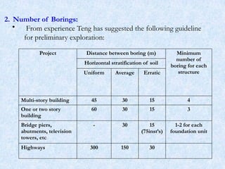
Project Distance betweenboring (m) Minimum
number of
boring for each
structure
Horizontal stratification of soil
Uniform Average Erratic
Multi-story building 45 30 15 4
One or two story
building
60 30 15 3
Bridge piers,
abutments, television
towers, etc
- 30 15
(75inst’s)
1-2 for each
foundation unit
Highways 300 150 30
2. Number of Borings:
• From experience Teng has suggested the following guideline
for preliminary exploration:
70
71.
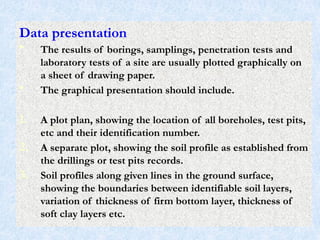
Data presentation
• Theresults of borings, samplings, penetration tests and
laboratory tests of a site are usually plotted graphically on
a sheet of drawing paper.
• The graphical presentation should include.
1. A plot plan, showing the location of all boreholes, test pits,
etc and their identification number.
2. A separate plot, showing the soil profile as established from
the drillings or test pits records.
3. Soil profiles along given lines in the ground surface,
showing the boundaries between identifiable soil layers,
variation of thickness of firm bottom layer, thickness of
soft clay layers etc.
71
72.
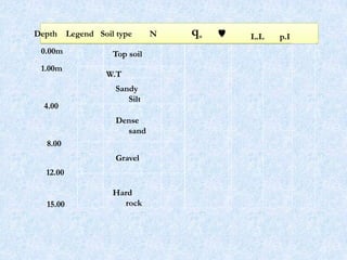
4. The penetrationnumber, the unconfined compression
strength, Atterberg limits, natural moisture content, and
other appropriate laboratory data may be shown on each
boring on the soil profile.
5. The location of ground water table should also be shown
on the soil profile.
72
Soil Exploration Report
Mostreports have the following contents:
1. Introduction: - Purpose of investigation, type of
investigation carried out.
2. General description of the site: - general configuration and
surface features of the site.
3. General geology of the area.
4. Description of soil conditions found in bore holes (and
test pits)
5. Laboratory test results.
6. Discussion of results of investigation in relation to
foundation design and constructions.
7. Conclusion: recommendations on the type and depth of
foundations, allowable bearing pressure and methods of
construction.
75


![Field [in-situ] tests
• These tests are valuable means of determining the
relative densities; shear strengths and bearing
capacities of soils directly without disturbing effects
of boring and sampling.
• The most commonly used field tests are:
Penetration or sounding tests
Vane shear test
Plate loading test
Pile loading test
32](https://image.slidesharecdn.com/lecturenote-chapteroneonsiteexploration-251229124438-aa825e90/85/Lecture-Note-Chapter-One-on-Site-Exploration-pptx-32-320.jpg)


![Foundation Eng'g-1, [Lecture Note] on Site Exploration [Chapter One].pptx](https://cdn.slidesharecdn.com/ss_thumbnails/foundationengg-1lecturenoteonsiteexplorationchapterone-251229124058-ecb78644-thumbnail.jpg?width=640&height=640&fit=bounds)


![[LNote], Foundation Types and Their Selection,[CH-Two].pptx](https://cdn.slidesharecdn.com/ss_thumbnails/lnotefoundationtypesandtheirselectionch-two-251229125133-9837d913-thumbnail.jpg?width=640&height=640&fit=bounds)


![[LN], [Chapter3.1], Foundation Eng'g-1, Bearing Capacity of Shallow Foundatio...](https://cdn.slidesharecdn.com/ss_thumbnails/lnchapter3-251229124520-79d90b38-thumbnail.jpg?width=640&height=640&fit=bounds)


