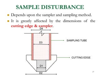
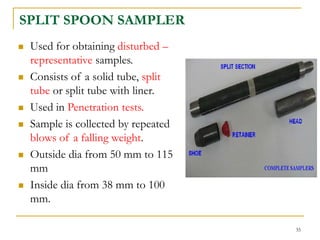
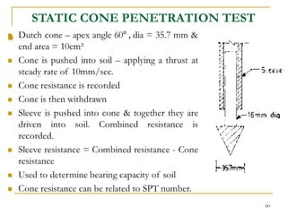
SUBSURFACE
EXPLORATION
1
OVERVIEW
I. SITE INVESTIGATION
II. SOIL EXPLORATION
III. OBJECTIVES
IV. PHASES OF EXPLORATION
V. METHODS OF EXPLORATION
I. OPEN EXCAVATION
II. BORING
III. SUBSURFACE SOUNDINGS
IV. GEOPHYSICAL METHODS
VI. BOREHOLE LOGS
VII. SOIL EXPLORATION REPORT
2
SITE INVESTIGATION
 Site investigation is an engineering programme used
to assess the suitability of a site for a proposed
construction work.
 It is also necessary in reporting the safety & causes
of failures of existing works.
3
Failures
4
Leaning Tower of Pisa
and Sinkholes
5
Steps in Site investigation:
1. Preliminary work
 Collecting general information and already existing
data such as study of geologic , seismic maps, etc.
at or near site.
 Study site history – if previously used as quarry,
agricultural land, industrial unit, etc.
2. Reconnaissance: Actual site inspection
 To judge general suitability
 Decide exploration techniques
3. Soil exploration
4. Report of investigations
6
SOIL EXPLORATION
 The field & laboratory studies carried out to obtain
the knowledge of sub-soil conditions for a safe &
economic design of substructures is called as SOIL
EXPLORATION.
7
OBJECTIVES OF SOIL
EXPLORATION
 To know geological conditions of soil and rock formations.
 To establish the ground water table & determine its properties.
 To select type & depth of foundation of proposed structure.
 To determine the bearing capacity of the site.
 To estimate probable settlement.
 To solve foundation problems.
 To predict suitable construction techniques.
 To select suitable construction material for foundation.
 To investigate the safety of existing structures & suggest
remedial measures. 8
PHASES OF EXPLORATION
A. PHASE 1- Collection of available information such as a site
plan, type, size, and importance of the structure, loading
conditions, previous geotechnical reports, topographic maps,
geologic maps, hydrological information and newspaper clippings.
B. PHASE 2 - Preliminary reconnaissance. Visual inspection is
done to gather information on topography, soil stratification,
vegetation, water marks, ground water level, and type of
construction nearby.
9
C. PHASE 3 - Detailed soil exploration in the form trial pits
or borings is carried out. The details of the soils
encountered, type of field tests adopted, type of sampling
done, presence of water table are recorded in the form of
bore log. The soil samples are properly labeled and sent to
laboratory to determine engineering properties.
D. PHASE 4 - Write a report containing a clear description of
the soils at the site, methods of exploration, soil profile, test
methods and results, and the location of the groundwater.
10
METHODS OF EXPLORATION
A. OPEN EXCAVATION
B. BORING
C. SUB SURFACE SOUNDINGS
D. GEOPHYSICAL METHODS
11
A. OPEN EXCAVATION
 Test pits
 Permits visual inspection of subsurface conditions in natural state.
 Max. depth limited to 3m. Working space of 1.2m x 1.2m is
required at the bottom of the pit.
 Used to obtain disturbed/ undisturbed samples.
 Trenches
 Used to provide a continuous exposure of soil strata.
12
 Shafts
 For greater depths, shafts are made with proper supports by
timber/ steel.
 Boreholes
 For depths greater than 6m & below WT.
 Tunnels
 Used to explore areas beneath steep slopes.
13
ADVANTAGES
 Detailed information of
soil stratigraphy
 Large quantities of
disturbed samples are
available for lab testing.
 Blocks of undisturbed
samples can be carved out.
 Bottom of pits can be used
for field tests.
DISADVANTAGES
 Deep pits are uneconomical
 Depth limited to 6m
 Excavation below WT is
difficult.
14
B. BORING
 Making & advancing of boreholes is known as
boring.
 Methods of Boring are:
 AUGER BORING
 AUGER & SHELL BORING
 WASH BORING
 PERCUSSION BORING
 ROTARY BORING
15
 AUGER BORING:
 Simplest method of exploration and sampling.
 Method:
 Auger is held vertically on ground surface & is
pressed out by rotating.
 Turning action cuts the soil which fills the annular
space.
 Auger is then withdrawn & cleaned. The process is
again repeated.
16
 Types: Hand operated or
Power driven .
 Hand operated augers
 Post hole augers
 Boring pits of sizes 7.5 to
30 cm in dia.
 Used for depth upto 6m.
 Casing pipes may be used
to prevent the collapse of
sides of boreholes.
 If stones are encountered,
chisel bits are used to
break them.
 Spiral/ Helical augers
CHISEL BITS
17
 Power driven augers
 Used for greater boring depths.
 Useful in hard & stiff soil strata.
 Continuous flight of augers are used.
 Useful in all soil types.
18
 Auger boring is suitable in loose, moderately cohesive soils,
partially saturated sand & silts.
 Max. depth 10 m
 Samples obtained are highly disturbed.
19
 PERCUSSION BORING:
 Percussion drilling
 Grinding the soil by repeated lifting and
dropping of heavy chisels or drilling bits.
 Water is added to form slurry of cuttings.
 Slurry removed by bailers or pumps.
BAILER 20
 In general, a machine used to drill holes is called a drill
rig (generally power driven, but may be hand driven).
 A winch is provided to raise and lower the drilling tools
into the hole.
 Sides of holes are stabilized by using casing or drilling
mud (Bentonite clay mixed with water).
 Useful in rocks, boulders & hard strata.
 Expensive method.
 Highly disturbed samples are obtained.
21
 ROTARY DRILLING
 Used to bore holes of few cm to 1m
dia & of greater depths.
 Can be used in clay, sand & rocks.
 Two types: Mud Rotary drilling &
Core drilling
 Mud Rotary drilling
 Hollow drill rods with a drill bit is
rotated into the soil by a chuck.
 Drilling mud is continuously
pumped into the hole through drill
rods.
 The bit grinds the soil and the
return flow brings the cuttings to
the surface.
 No casing used.
22
 Core drilling
 Used for obtaining rock cores.
 A core barrel is fitted with a
drill bit is attached to a string of
hollow drill rods and is rotated
into the hole.
 As the bit advances, rock core
passes to the barrel & is
retained by core lifter.
 Bit is kept cool by pumping
water through drill rods.
 Examples: diamond bit or steel
bit.
23
TYPES OF SAMPLES
 DISTURBED SAMPLES
 REPRESENTATIVE – DISTURBED SAMPLES
 NON REPRESENTATIVE – DISTURBED
SAMPLES
 UNDISTURBED SAMPLES
24
DISTURBED SAMPLES
 Samples in which the natural soil structure gets destroyed or
modified during the sampling operations.
 REPRESENTATIVE SAMPLES: Disturbed samples whose
moisture content & proportion of mineral constituents can be
preserved.
 Used to determine the index properties (grain size, plasticity
characteristics, specific gravity).
 Used for compaction tests, stabilization tests etc.
 NON - REPRESENTATIVE SAMPLES: Disturbed samples in
which the moisture content & proportion of mineral constituents
cannot be preserved. They are virtually of no use.
 Obtained during auger boring & percussion drilling.
25
UNDISTURBED SAMPLES
 Samples in which the natural soil structure is preserved
& the properties have not changed during the sampling
operations.
 Suitable to determine engineering properties such as
compressibility, shear strength & permeability and
index properties like Atterberg’s limits.
 Obtained using samplers like Shelby tube, piston
sampler etc.
26
SAMPLE DISTURBANCE
 Depends upon the sampler and sampling method.
 It is greatly affected by the dimensions of the
cutting edge & sampler.
D4
D3
D1
D2
D3
SAMPLING TUBE
CUTTING EDGE
27
Design features affecting the sample
disturbance:

28
Design features affecting the sample
disturbance:

29
Design features affecting the sample
disturbance:

30
Design features affecting the sample
disturbance:

31
Design features affecting the sample
disturbance:

32
SAMPLERS
1. OPEN DRIVE SAMPLERS
1. SPLIT SPOON SAMPLER
2. SHELBY TUBE SAMPLER
2. STATIONARY PISTON SAMPLERS
3. ROTARY SAMPLERS
4. BLOCK / CHUNK SAMPLES
33
1. OPEN DRIVE SAMPLERS
 Consists of a seamless – open ended steel tube with a cutting
edge.
 Tube is connected to a drill rod.
 Sampler head has vents – permits water & air to escape
during sampling.
 Check valve – retains the sample in the tube, while it is
withdrawn.
 Two types:
1. SPLIT SPOON SAMPLER
2. SHELBY TUBE SAMPLER
34
SPLIT SPOON SAMPLER
 Used for obtaining disturbed –
representative samples.
 Consists of a solid tube, split
tube or split tube with liner.
 Used in Penetration tests.
 Sample is collected by repeated
blows of a falling weight.
 Outside dia from 50 mm to 115
mm
 Inside dia from 38 mm to 100
mm.
35

36
SHELBY TUBE SAMPLER

37
 Length of sampler is such that it can
be penetrated into:
 Sandy soils from 5 to 10 times dia
 Clays from 10 to 15 times dia
 Sampler attached to the drill rod is
pushed into the soil from the bottom
of borehole by a continuous rapid
motion.
38
2. STATIONARY PISTON SAMPLER
 It is a thin wall sampler with a piston
inside.
 Piston is attached to the piston rod.
 Piston keeps the lower end of the
sampling tube closed, when sampler is
lowered to the bottom of hole.
 Once the sampler is lowered, piston is
prevented from moving downwards
using locking cone.
 Sampler is pushed past the piston to
obtain the sample.
 Piston remains in contact with the top of
the sample – it prevents sample
disturbances. 39
 Used in saturated sands & wet / soft clays to obtain
undisturbed samples
 Cannot be used in Hard & gravelly soils.
40
3. ROTARY SAMPLER
 Double walled tube sampler with
an inner removable liner.
 Outer tube has removable cutting
bit at its bottom, which rotates &
cut the soil.
 Cuttings are washed up from
borehole using water/ drilling mud,
which is continuously pumped
through drill rods & flows btw the
tubes.
 Inner tube has a spring core
catcher to retain the sample.
 Sample is received in inner liner.
41
 Used in hard rocks, firm to hard
cohesive soils & slightly cohesive sands
 Not suitable for gravelly soils, loose
sands & silts below WT & very soft
cohesive soils.
 Quality of sample can be estimated
using a ratio – RQD (Rock Quality
Designation)
 RQD = measure of amount of
fracturing/weathering in rocks
42
RQD ROCK
QUALITY
<25 Very poor
25 – 50 Poor
50 – 75 Fair
75 – 90 Good
90 – 100 Excellent
4. BLOCK OR CHUNK
SAMPLES
 Obtained from open excavations.
 Possible in cohesive soils.
 Soil block of 40cm x 40 cm is left undisturbed during
excavation.
 From this, a 30 x 30 cm block is trimmed out
undisturbed.
 Open ended box is made to slide over the trimmed
block.
 Space btw box & sample is filled with sand & top is
sealed with paraffin wax.
 Box is then cut out from base using a spade. 43
44
DEPTH OF EXPLORATION
 Should be done up to which the pressure due to
building loads causes undesirable settlement or shear
failure – Significant depth.
 = 1.5 to 2 times width of loaded area.
 Depends on :
 Type of structure
 Load intensity
 Size, shape & disposition of loaded areas
 Soil profile & properties.
45
ISOLATED SPREAD FOOTING / RAFT 1.5 B (WIDTH)
ADJACENT FOOTINGS WITH CLEAR SPACING < 2B 1.5 L
ADJACENT FOOTINGS WITH CLEAR SPACING ≥ 4B 1.5 B
PILE FOUNDATIONS 10 to 30 m or 1.5 B
BASE OF RETAINING WALL 1.5 B or 1.5 H (greater)
DAMS 0.5 B or 2 H
ROAD CUTS 1 m
ROAD FILLS 2 m below GL
or
Ht of fill abv GL, (greater)
CONSIDERING WEATHERING 1.5 m , in general
3.5 m in black cotton soil
MULTISTOREYED BUILDINGS
46
NUMBER & SPACING OF
BORINGS
 It should be such as to reveal any major changes in
thickness, depth or properties of strata affected by
construction or immediate surroundings.
47
Multi storeyed building 10 – 30 m
Industrial plant 20 – 60 m
Highway 250 – 500 m
Residential subdivision 250 – 500 m
Dams & dikes 40 – 80 m
SPACING OF BOREHOLES
48
Compact building site 0.4
hectares area
1 in each corner & 1 at centre
Small & less important
building sites < 0.4 hectares
area
1 at centre
Large area buildings > 0.4
hectares
Area divided into grids & 1 at every
100m
Dam sites 1 at every 50 m spacing along top line
of upstream side & across abutments.
Road sites 1 at every 100 m spacing along centre
line & both side ditch lines.
1 at every 500 m, on uniform soils
1 at every 30 m, on non-uniform soils
NUMBER OF BOREHOLES
SUB SURFACE SOUNDINGS
Sub surface sounding is in-situ determination of variation
in penetration resistance of a soil deposit along vertical
lines. APPLICATIONS
 To locate bedrock or hard strata underlying soft and loose
strata.
 To explore an erratic soil profile
 To determine boundaries of soft pockets.
 To get information on the relative density of cohesionless
soils and consistency of cohesive soil.
 To estimate the approximate bearing capacity of soil, length
and bearing capacity of piles and settlement of foundation.
49
TYPES OF SOUNDING OR
PENETRATION TEST
 STANDARD PENETRATION TEST
 CONE PENETRATION TEST
50
STANDARD PENETRATION
TEST (SPT)
 Most extensively used method in India
 Suitable in cohesionless soils
 Carried out in a borehole, which is clean having 55 to 150 mm
diameter.
 The borehole is advanced to required depth and cleaned.
 Casing / Drilling mud is used to support sides.
 Split spoon sampler dia inner 35mm & outer 50.8mm is driven
for a distance of 450 mm with hammer of -
 weight 65kg
 Drop 750mm
 Rate of penetration 30mm/minute
51
 No of blows for every 150mm is recorded.
 Blows for first 150mm penetration is discarded – seating drive.
 The blows for last 2 penetrations are added together to give the
STANDARD PENETRATION NUMBER(N value).
 Sampler is withdrawn and detached from drill rod.
 Sample is extracted and sealed with paraffin wax and transported
for testing.
 SPT is carried out at every 0.75 or 1m depth.
 It is discontinued if :
 Blows 50 – for 150mm
 Blows 100- for 300mm
 10 successive blows produce no advance.
 Sample obtained- representative, disturbed.
52
SPT CORRECTIONS
 OVERBURDEN PRESSURE CORRECTION
 DILATANCY CORRECTION
53
Overburden pressure correction
 Significant in granular soils
 As depth increases, confining pressure also increases in granular
soils.
 N value will be over estimated for greater depths
 N value will be under estimated for shallow depths.
 N values are corrected to a Standard effective overburden
pressure.
54

55
Dilatancy correction (fine sand & silt)

56
57
58
CONE PENETRATION TEST
(CPT)
 Also called as Dutch cone test.
 Useful in cohesionless soil & soft
sensitive silt & clay.
 Soil sample cannot be obtained.
 Types:
 STATIC CONE
PENETRATION TEST
 DYNAMIC CONE TEST
59
STATIC CONE PENETRATION TEST

60
61

62
DYNAMIC CONE TEST

63

64
METHODS OF EXPLORATION
A. OPEN EXCAVATION
B. BORING
C. SUB SURFACE SOUNDINGS
D. GEOPHYSICAL METHODS
65
GEOPHYSICAL METHODS
 Used in preliminary investigations of sub soil strata
to locate different soil layers & for rapid evaluation
of soil characteristics.
 Two methods:
 SEISMIC REFRACTION METHOD
 ELECTRICAL RESISTIVITY METHOD
66
SEISMIC REFRACTION METHOD
 PRINCIPLE: seismic waves have different
velocities in different types of soil/ rock.
 It gets refracted – when it crosses the
boundaries – as different soil types possess
different elastic properties.
 Used to determine soil types & approx. depth of
soil strata.
67
68
Procedure:
 An IMPACT or SHOCK is generated –
 by striking a plate on soil with hammer
 by exploding a small charge at/ near ground surface.
 Vibration detectors called as GEOPHONES, placed
on ground surface at a certain distance from the
SOURCE, picks up the radiating shock waves.
 Geophones/ SEISMOMETER – record the time of
travel of waves.
69
70
A B
V1
V2
Z1
Z2
TOP
SOIL
DENSER
SOIL
Refracted waves (V2)
Refracted waves (V3)
Direct waves (V1)
B
D1 D2
A
 Direct/Primary waves travel directly from source
along the ground surface & are picked up by first
geophone.
 If subsoil has more layers – waves travel
downwards to lower layer & get refracted at the
interface b/w layers.
 If lower layer is denser, - refracted waves travel
faster – merge again - & reach geophone.
 As distance b/w Source & Geophone increases –
refracted waves will reach faster than direct waves.
71
 P – source – shock waves are generated here.
 A & B - Geophones – record the arrival of waves &
convert them to electrical impulses & transmit to
recording devices.
 V1 – velocity of direct waves
 V2 – velocity of refracted waves from top layer
 V3 – velocity of refracted waves from denser layer.
 V3 > V2 > V1
72
73
DISTANCE – TIME
GRAPH

74

75
Limitations
 Not applicable, if a hard layer overlies a softer layer
with smaller seismic velocity.
 Not applicable in areas covered with concrete,
asphalt pavement , underground conduits, irregular
WT, frozen soil layer.
 Costly
 Requires sophisticated equipment & expert persons
for interpreting the results.
76
ELECTRICAL RESISTIVITY
METHOD
77
78
79
Electrical Profiling / Resistivity
mapping
 4 electrodes in the form of metal spikes are
driven into soil
 Outer 2 – current electrodes
 Inner 2 – potential electrodes
 DC is applied to outer electrodes & Voltage
drop b/w inner electrodes are then measured.
 To know horizontal changes in sub – soil, the
electrodes kept at a constant spacing are
moved as a group along the test line.
80
81
Mean resistivity is given as,
d
Electrical Sounding / Resistivity
Sounding
 To study vertical changes in soil strata,
electrode system is expanded, by increasing
spacing b/w electrodes upto a distance equal
to depth required.
82
Limitations
 The methods are capable of detecting only the strata
having different electrical resistivity.
 The results are considerably influenced by surface
irregularities, wetness of the strata and electrolyte
concentration of the ground water.
 As the resistivity of different strata at the interface
changes gradually and not abruptly as assumed, then
the interpolation becomes difficult.
 The services of an expert in the field are needed
83
STABILIZATION OF BOREHOLE
 It is important to prevent the caving in of the sides
of a borehole, while it is drilled in successive stages.
 METHODS:
1. SELF SUPPORTING BOREHOLE
2. BY FILLING WATER ABOVE GWT
3. BY FILLING DRILLING MUD ABOVE GWT
4. BY CASING PIPE & FILLING WITH WATER
ABOVE GWT
84
1. SELF SUPPORTING BOREHOLE
 In clays, boreholes are self-supportive because:
 Dry – above WT – have apparent cohesion
 Wet – below WT – have undrained shear
strength
 In silt, boreholes are self-supportive because of
cohesion due to negative pore pressure.
2. BY FILLING WATER ABOVE GWT
 GWT- above the water in borehole – seepage
forces push the soil particles into the hole.
 If water level in hole is raised - flow will be
reverse & the soil particles will remain in original
position.
 Suitable in sandy soil 85
3. BY FILLING DRILLING MUD ABOVE GWT
 Drilling mud/ Bentonite coating on sides of borehole –
have low permeability & high plasticity - prevents caving
in.
 Suitable in fine sand.
4. BY CASING PIPE & FILLING WITH WATER ABOVE
GWT
 Suitable in medium & coarse sand & soft clays
86
BORELOG
 After the soil investigation has been completed &
the laboratory results are available, the ground
conditions discovered in each borehole is
summarized in the form of a BORELOG.
87
 It consists of :
 Name of Project & Client
 Method of investigation & Details of equipment
used
 Date of Start & Completion of project
 Location, Ground level & diameter of borehole.
 Soil profile & elevations of different strata
 Ground water level
 Depths at which tests are done & samples are taken.
 Types of soil samples
 Results of important Lab tests
 N values obtained at various depths
88
89
SOIL EXPLORATION
REPORT
90
 It should contain the following data:
1. Introduction
 Scope of investigation
 Nature of project
2. Location & Description of the site & its geological conditions.
3. Details of soil exploration programme – Number of borings,
their location, depth etc.
4. Methods of exploration
5. Laboratory & Field tests conducted & their results, tables,
plots, test procedure, IS standards etc.
6. Depth of Ground water table & their changes
7. Borelogs & representation of data from a number of
boreholes as a surface profile.
91
92
8. Analysis of Data. It should include:
 Reference to Borelog & subsurface profile
 RL of GWT
 Calculations for recommended type of foundation, size,
depth, allowable bearing pressure etc.
9. Recommendations
10. Conclusions
11. Limitations of investigation
12. References & relevant literature extracts.
93

SOIL EXPLORATION

  • 1.
  • 2.
    OVERVIEW I. SITE INVESTIGATION II.SOIL EXPLORATION III. OBJECTIVES IV. PHASES OF EXPLORATION V. METHODS OF EXPLORATION I. OPEN EXCAVATION II. BORING III. SUBSURFACE SOUNDINGS IV. GEOPHYSICAL METHODS VI. BOREHOLE LOGS VII. SOIL EXPLORATION REPORT 2
  • 3.
    SITE INVESTIGATION  Siteinvestigation is an engineering programme used to assess the suitability of a site for a proposed construction work.  It is also necessary in reporting the safety & causes of failures of existing works. 3
  • 4.
  • 5.
    Leaning Tower ofPisa and Sinkholes 5
  • 6.
    Steps in Siteinvestigation: 1. Preliminary work  Collecting general information and already existing data such as study of geologic , seismic maps, etc. at or near site.  Study site history – if previously used as quarry, agricultural land, industrial unit, etc. 2. Reconnaissance: Actual site inspection  To judge general suitability  Decide exploration techniques 3. Soil exploration 4. Report of investigations 6
  • 7.
    SOIL EXPLORATION  Thefield & laboratory studies carried out to obtain the knowledge of sub-soil conditions for a safe & economic design of substructures is called as SOIL EXPLORATION. 7
  • 8.
    OBJECTIVES OF SOIL EXPLORATION To know geological conditions of soil and rock formations.  To establish the ground water table & determine its properties.  To select type & depth of foundation of proposed structure.  To determine the bearing capacity of the site.  To estimate probable settlement.  To solve foundation problems.  To predict suitable construction techniques.  To select suitable construction material for foundation.  To investigate the safety of existing structures & suggest remedial measures. 8
  • 9.
    PHASES OF EXPLORATION A.PHASE 1- Collection of available information such as a site plan, type, size, and importance of the structure, loading conditions, previous geotechnical reports, topographic maps, geologic maps, hydrological information and newspaper clippings. B. PHASE 2 - Preliminary reconnaissance. Visual inspection is done to gather information on topography, soil stratification, vegetation, water marks, ground water level, and type of construction nearby. 9
  • 10.
    C. PHASE 3- Detailed soil exploration in the form trial pits or borings is carried out. The details of the soils encountered, type of field tests adopted, type of sampling done, presence of water table are recorded in the form of bore log. The soil samples are properly labeled and sent to laboratory to determine engineering properties. D. PHASE 4 - Write a report containing a clear description of the soils at the site, methods of exploration, soil profile, test methods and results, and the location of the groundwater. 10
  • 11.
    METHODS OF EXPLORATION A.OPEN EXCAVATION B. BORING C. SUB SURFACE SOUNDINGS D. GEOPHYSICAL METHODS 11
  • 12.
    A. OPEN EXCAVATION Test pits  Permits visual inspection of subsurface conditions in natural state.  Max. depth limited to 3m. Working space of 1.2m x 1.2m is required at the bottom of the pit.  Used to obtain disturbed/ undisturbed samples.  Trenches  Used to provide a continuous exposure of soil strata. 12
  • 13.
     Shafts  Forgreater depths, shafts are made with proper supports by timber/ steel.  Boreholes  For depths greater than 6m & below WT.  Tunnels  Used to explore areas beneath steep slopes. 13
  • 14.
    ADVANTAGES  Detailed informationof soil stratigraphy  Large quantities of disturbed samples are available for lab testing.  Blocks of undisturbed samples can be carved out.  Bottom of pits can be used for field tests. DISADVANTAGES  Deep pits are uneconomical  Depth limited to 6m  Excavation below WT is difficult. 14
  • 15.
    B. BORING  Making& advancing of boreholes is known as boring.  Methods of Boring are:  AUGER BORING  AUGER & SHELL BORING  WASH BORING  PERCUSSION BORING  ROTARY BORING 15
  • 16.
     AUGER BORING: Simplest method of exploration and sampling.  Method:  Auger is held vertically on ground surface & is pressed out by rotating.  Turning action cuts the soil which fills the annular space.  Auger is then withdrawn & cleaned. The process is again repeated. 16
  • 17.
     Types: Handoperated or Power driven .  Hand operated augers  Post hole augers  Boring pits of sizes 7.5 to 30 cm in dia.  Used for depth upto 6m.  Casing pipes may be used to prevent the collapse of sides of boreholes.  If stones are encountered, chisel bits are used to break them.  Spiral/ Helical augers CHISEL BITS 17
  • 18.
     Power drivenaugers  Used for greater boring depths.  Useful in hard & stiff soil strata.  Continuous flight of augers are used.  Useful in all soil types. 18
  • 19.
     Auger boringis suitable in loose, moderately cohesive soils, partially saturated sand & silts.  Max. depth 10 m  Samples obtained are highly disturbed. 19
  • 20.
     PERCUSSION BORING: Percussion drilling  Grinding the soil by repeated lifting and dropping of heavy chisels or drilling bits.  Water is added to form slurry of cuttings.  Slurry removed by bailers or pumps. BAILER 20
  • 21.
     In general,a machine used to drill holes is called a drill rig (generally power driven, but may be hand driven).  A winch is provided to raise and lower the drilling tools into the hole.  Sides of holes are stabilized by using casing or drilling mud (Bentonite clay mixed with water).  Useful in rocks, boulders & hard strata.  Expensive method.  Highly disturbed samples are obtained. 21
  • 22.
     ROTARY DRILLING Used to bore holes of few cm to 1m dia & of greater depths.  Can be used in clay, sand & rocks.  Two types: Mud Rotary drilling & Core drilling  Mud Rotary drilling  Hollow drill rods with a drill bit is rotated into the soil by a chuck.  Drilling mud is continuously pumped into the hole through drill rods.  The bit grinds the soil and the return flow brings the cuttings to the surface.  No casing used. 22
  • 23.
     Core drilling Used for obtaining rock cores.  A core barrel is fitted with a drill bit is attached to a string of hollow drill rods and is rotated into the hole.  As the bit advances, rock core passes to the barrel & is retained by core lifter.  Bit is kept cool by pumping water through drill rods.  Examples: diamond bit or steel bit. 23
  • 24.
    TYPES OF SAMPLES DISTURBED SAMPLES  REPRESENTATIVE – DISTURBED SAMPLES  NON REPRESENTATIVE – DISTURBED SAMPLES  UNDISTURBED SAMPLES 24
  • 25.
    DISTURBED SAMPLES  Samplesin which the natural soil structure gets destroyed or modified during the sampling operations.  REPRESENTATIVE SAMPLES: Disturbed samples whose moisture content & proportion of mineral constituents can be preserved.  Used to determine the index properties (grain size, plasticity characteristics, specific gravity).  Used for compaction tests, stabilization tests etc.  NON - REPRESENTATIVE SAMPLES: Disturbed samples in which the moisture content & proportion of mineral constituents cannot be preserved. They are virtually of no use.  Obtained during auger boring & percussion drilling. 25
  • 26.
    UNDISTURBED SAMPLES  Samplesin which the natural soil structure is preserved & the properties have not changed during the sampling operations.  Suitable to determine engineering properties such as compressibility, shear strength & permeability and index properties like Atterberg’s limits.  Obtained using samplers like Shelby tube, piston sampler etc. 26
  • 27.
    SAMPLE DISTURBANCE  Dependsupon the sampler and sampling method.  It is greatly affected by the dimensions of the cutting edge & sampler. D4 D3 D1 D2 D3 SAMPLING TUBE CUTTING EDGE 27
  • 28.
    Design features affectingthe sample disturbance:  28
  • 29.
    Design features affectingthe sample disturbance:  29
  • 30.
    Design features affectingthe sample disturbance:  30
  • 31.
    Design features affectingthe sample disturbance:  31
  • 32.
    Design features affectingthe sample disturbance:  32
  • 33.
    SAMPLERS 1. OPEN DRIVESAMPLERS 1. SPLIT SPOON SAMPLER 2. SHELBY TUBE SAMPLER 2. STATIONARY PISTON SAMPLERS 3. ROTARY SAMPLERS 4. BLOCK / CHUNK SAMPLES 33
  • 34.
    1. OPEN DRIVESAMPLERS  Consists of a seamless – open ended steel tube with a cutting edge.  Tube is connected to a drill rod.  Sampler head has vents – permits water & air to escape during sampling.  Check valve – retains the sample in the tube, while it is withdrawn.  Two types: 1. SPLIT SPOON SAMPLER 2. SHELBY TUBE SAMPLER 34
  • 35.
    SPLIT SPOON SAMPLER Used for obtaining disturbed – representative samples.  Consists of a solid tube, split tube or split tube with liner.  Used in Penetration tests.  Sample is collected by repeated blows of a falling weight.  Outside dia from 50 mm to 115 mm  Inside dia from 38 mm to 100 mm. 35
  • 36.
  • 37.
  • 38.
     Length ofsampler is such that it can be penetrated into:  Sandy soils from 5 to 10 times dia  Clays from 10 to 15 times dia  Sampler attached to the drill rod is pushed into the soil from the bottom of borehole by a continuous rapid motion. 38
  • 39.
    2. STATIONARY PISTONSAMPLER  It is a thin wall sampler with a piston inside.  Piston is attached to the piston rod.  Piston keeps the lower end of the sampling tube closed, when sampler is lowered to the bottom of hole.  Once the sampler is lowered, piston is prevented from moving downwards using locking cone.  Sampler is pushed past the piston to obtain the sample.  Piston remains in contact with the top of the sample – it prevents sample disturbances. 39
  • 40.
     Used insaturated sands & wet / soft clays to obtain undisturbed samples  Cannot be used in Hard & gravelly soils. 40
  • 41.
    3. ROTARY SAMPLER Double walled tube sampler with an inner removable liner.  Outer tube has removable cutting bit at its bottom, which rotates & cut the soil.  Cuttings are washed up from borehole using water/ drilling mud, which is continuously pumped through drill rods & flows btw the tubes.  Inner tube has a spring core catcher to retain the sample.  Sample is received in inner liner. 41
  • 42.
     Used inhard rocks, firm to hard cohesive soils & slightly cohesive sands  Not suitable for gravelly soils, loose sands & silts below WT & very soft cohesive soils.  Quality of sample can be estimated using a ratio – RQD (Rock Quality Designation)  RQD = measure of amount of fracturing/weathering in rocks 42 RQD ROCK QUALITY <25 Very poor 25 – 50 Poor 50 – 75 Fair 75 – 90 Good 90 – 100 Excellent
  • 43.
    4. BLOCK ORCHUNK SAMPLES  Obtained from open excavations.  Possible in cohesive soils.  Soil block of 40cm x 40 cm is left undisturbed during excavation.  From this, a 30 x 30 cm block is trimmed out undisturbed.  Open ended box is made to slide over the trimmed block.  Space btw box & sample is filled with sand & top is sealed with paraffin wax.  Box is then cut out from base using a spade. 43
  • 44.
  • 45.
    DEPTH OF EXPLORATION Should be done up to which the pressure due to building loads causes undesirable settlement or shear failure – Significant depth.  = 1.5 to 2 times width of loaded area.  Depends on :  Type of structure  Load intensity  Size, shape & disposition of loaded areas  Soil profile & properties. 45
  • 46.
    ISOLATED SPREAD FOOTING/ RAFT 1.5 B (WIDTH) ADJACENT FOOTINGS WITH CLEAR SPACING < 2B 1.5 L ADJACENT FOOTINGS WITH CLEAR SPACING ≥ 4B 1.5 B PILE FOUNDATIONS 10 to 30 m or 1.5 B BASE OF RETAINING WALL 1.5 B or 1.5 H (greater) DAMS 0.5 B or 2 H ROAD CUTS 1 m ROAD FILLS 2 m below GL or Ht of fill abv GL, (greater) CONSIDERING WEATHERING 1.5 m , in general 3.5 m in black cotton soil MULTISTOREYED BUILDINGS 46
  • 47.
    NUMBER & SPACINGOF BORINGS  It should be such as to reveal any major changes in thickness, depth or properties of strata affected by construction or immediate surroundings. 47 Multi storeyed building 10 – 30 m Industrial plant 20 – 60 m Highway 250 – 500 m Residential subdivision 250 – 500 m Dams & dikes 40 – 80 m SPACING OF BOREHOLES
  • 48.
    48 Compact building site0.4 hectares area 1 in each corner & 1 at centre Small & less important building sites < 0.4 hectares area 1 at centre Large area buildings > 0.4 hectares Area divided into grids & 1 at every 100m Dam sites 1 at every 50 m spacing along top line of upstream side & across abutments. Road sites 1 at every 100 m spacing along centre line & both side ditch lines. 1 at every 500 m, on uniform soils 1 at every 30 m, on non-uniform soils NUMBER OF BOREHOLES
  • 49.
    SUB SURFACE SOUNDINGS Subsurface sounding is in-situ determination of variation in penetration resistance of a soil deposit along vertical lines. APPLICATIONS  To locate bedrock or hard strata underlying soft and loose strata.  To explore an erratic soil profile  To determine boundaries of soft pockets.  To get information on the relative density of cohesionless soils and consistency of cohesive soil.  To estimate the approximate bearing capacity of soil, length and bearing capacity of piles and settlement of foundation. 49
  • 50.
    TYPES OF SOUNDINGOR PENETRATION TEST  STANDARD PENETRATION TEST  CONE PENETRATION TEST 50
  • 51.
    STANDARD PENETRATION TEST (SPT) Most extensively used method in India  Suitable in cohesionless soils  Carried out in a borehole, which is clean having 55 to 150 mm diameter.  The borehole is advanced to required depth and cleaned.  Casing / Drilling mud is used to support sides.  Split spoon sampler dia inner 35mm & outer 50.8mm is driven for a distance of 450 mm with hammer of -  weight 65kg  Drop 750mm  Rate of penetration 30mm/minute 51
  • 52.
     No ofblows for every 150mm is recorded.  Blows for first 150mm penetration is discarded – seating drive.  The blows for last 2 penetrations are added together to give the STANDARD PENETRATION NUMBER(N value).  Sampler is withdrawn and detached from drill rod.  Sample is extracted and sealed with paraffin wax and transported for testing.  SPT is carried out at every 0.75 or 1m depth.  It is discontinued if :  Blows 50 – for 150mm  Blows 100- for 300mm  10 successive blows produce no advance.  Sample obtained- representative, disturbed. 52
  • 53.
    SPT CORRECTIONS  OVERBURDENPRESSURE CORRECTION  DILATANCY CORRECTION 53
  • 54.
    Overburden pressure correction Significant in granular soils  As depth increases, confining pressure also increases in granular soils.  N value will be over estimated for greater depths  N value will be under estimated for shallow depths.  N values are corrected to a Standard effective overburden pressure. 54
  • 55.
  • 56.
    Dilatancy correction (finesand & silt)  56
  • 57.
  • 58.
  • 59.
    CONE PENETRATION TEST (CPT) Also called as Dutch cone test.  Useful in cohesionless soil & soft sensitive silt & clay.  Soil sample cannot be obtained.  Types:  STATIC CONE PENETRATION TEST  DYNAMIC CONE TEST 59
  • 60.
  • 61.
  • 62.
  • 63.
  • 64.
  • 65.
    METHODS OF EXPLORATION A.OPEN EXCAVATION B. BORING C. SUB SURFACE SOUNDINGS D. GEOPHYSICAL METHODS 65
  • 66.
    GEOPHYSICAL METHODS  Usedin preliminary investigations of sub soil strata to locate different soil layers & for rapid evaluation of soil characteristics.  Two methods:  SEISMIC REFRACTION METHOD  ELECTRICAL RESISTIVITY METHOD 66
  • 67.
    SEISMIC REFRACTION METHOD PRINCIPLE: seismic waves have different velocities in different types of soil/ rock.  It gets refracted – when it crosses the boundaries – as different soil types possess different elastic properties.  Used to determine soil types & approx. depth of soil strata. 67
  • 68.
  • 69.
    Procedure:  An IMPACTor SHOCK is generated –  by striking a plate on soil with hammer  by exploding a small charge at/ near ground surface.  Vibration detectors called as GEOPHONES, placed on ground surface at a certain distance from the SOURCE, picks up the radiating shock waves.  Geophones/ SEISMOMETER – record the time of travel of waves. 69
  • 70.
    70 A B V1 V2 Z1 Z2 TOP SOIL DENSER SOIL Refracted waves(V2) Refracted waves (V3) Direct waves (V1) B D1 D2 A
  • 71.
     Direct/Primary wavestravel directly from source along the ground surface & are picked up by first geophone.  If subsoil has more layers – waves travel downwards to lower layer & get refracted at the interface b/w layers.  If lower layer is denser, - refracted waves travel faster – merge again - & reach geophone.  As distance b/w Source & Geophone increases – refracted waves will reach faster than direct waves. 71
  • 72.
     P –source – shock waves are generated here.  A & B - Geophones – record the arrival of waves & convert them to electrical impulses & transmit to recording devices.  V1 – velocity of direct waves  V2 – velocity of refracted waves from top layer  V3 – velocity of refracted waves from denser layer.  V3 > V2 > V1 72
  • 73.
  • 74.
  • 75.
  • 76.
    Limitations  Not applicable,if a hard layer overlies a softer layer with smaller seismic velocity.  Not applicable in areas covered with concrete, asphalt pavement , underground conduits, irregular WT, frozen soil layer.  Costly  Requires sophisticated equipment & expert persons for interpreting the results. 76
  • 77.
  • 78.
  • 79.
  • 80.
    Electrical Profiling /Resistivity mapping  4 electrodes in the form of metal spikes are driven into soil  Outer 2 – current electrodes  Inner 2 – potential electrodes  DC is applied to outer electrodes & Voltage drop b/w inner electrodes are then measured.  To know horizontal changes in sub – soil, the electrodes kept at a constant spacing are moved as a group along the test line. 80
  • 81.
  • 82.
    Electrical Sounding /Resistivity Sounding  To study vertical changes in soil strata, electrode system is expanded, by increasing spacing b/w electrodes upto a distance equal to depth required. 82
  • 83.
    Limitations  The methodsare capable of detecting only the strata having different electrical resistivity.  The results are considerably influenced by surface irregularities, wetness of the strata and electrolyte concentration of the ground water.  As the resistivity of different strata at the interface changes gradually and not abruptly as assumed, then the interpolation becomes difficult.  The services of an expert in the field are needed 83
  • 84.
    STABILIZATION OF BOREHOLE It is important to prevent the caving in of the sides of a borehole, while it is drilled in successive stages.  METHODS: 1. SELF SUPPORTING BOREHOLE 2. BY FILLING WATER ABOVE GWT 3. BY FILLING DRILLING MUD ABOVE GWT 4. BY CASING PIPE & FILLING WITH WATER ABOVE GWT 84
  • 85.
    1. SELF SUPPORTINGBOREHOLE  In clays, boreholes are self-supportive because:  Dry – above WT – have apparent cohesion  Wet – below WT – have undrained shear strength  In silt, boreholes are self-supportive because of cohesion due to negative pore pressure. 2. BY FILLING WATER ABOVE GWT  GWT- above the water in borehole – seepage forces push the soil particles into the hole.  If water level in hole is raised - flow will be reverse & the soil particles will remain in original position.  Suitable in sandy soil 85
  • 86.
    3. BY FILLINGDRILLING MUD ABOVE GWT  Drilling mud/ Bentonite coating on sides of borehole – have low permeability & high plasticity - prevents caving in.  Suitable in fine sand. 4. BY CASING PIPE & FILLING WITH WATER ABOVE GWT  Suitable in medium & coarse sand & soft clays 86
  • 87.
    BORELOG  After thesoil investigation has been completed & the laboratory results are available, the ground conditions discovered in each borehole is summarized in the form of a BORELOG. 87
  • 88.
     It consistsof :  Name of Project & Client  Method of investigation & Details of equipment used  Date of Start & Completion of project  Location, Ground level & diameter of borehole.  Soil profile & elevations of different strata  Ground water level  Depths at which tests are done & samples are taken.  Types of soil samples  Results of important Lab tests  N values obtained at various depths 88
  • 89.
  • 90.
  • 91.
     It shouldcontain the following data: 1. Introduction  Scope of investigation  Nature of project 2. Location & Description of the site & its geological conditions. 3. Details of soil exploration programme – Number of borings, their location, depth etc. 4. Methods of exploration 5. Laboratory & Field tests conducted & their results, tables, plots, test procedure, IS standards etc. 6. Depth of Ground water table & their changes 7. Borelogs & representation of data from a number of boreholes as a surface profile. 91
  • 92.
  • 93.
    8. Analysis ofData. It should include:  Reference to Borelog & subsurface profile  RL of GWT  Calculations for recommended type of foundation, size, depth, allowable bearing pressure etc. 9. Recommendations 10. Conclusions 11. Limitations of investigation 12. References & relevant literature extracts. 93