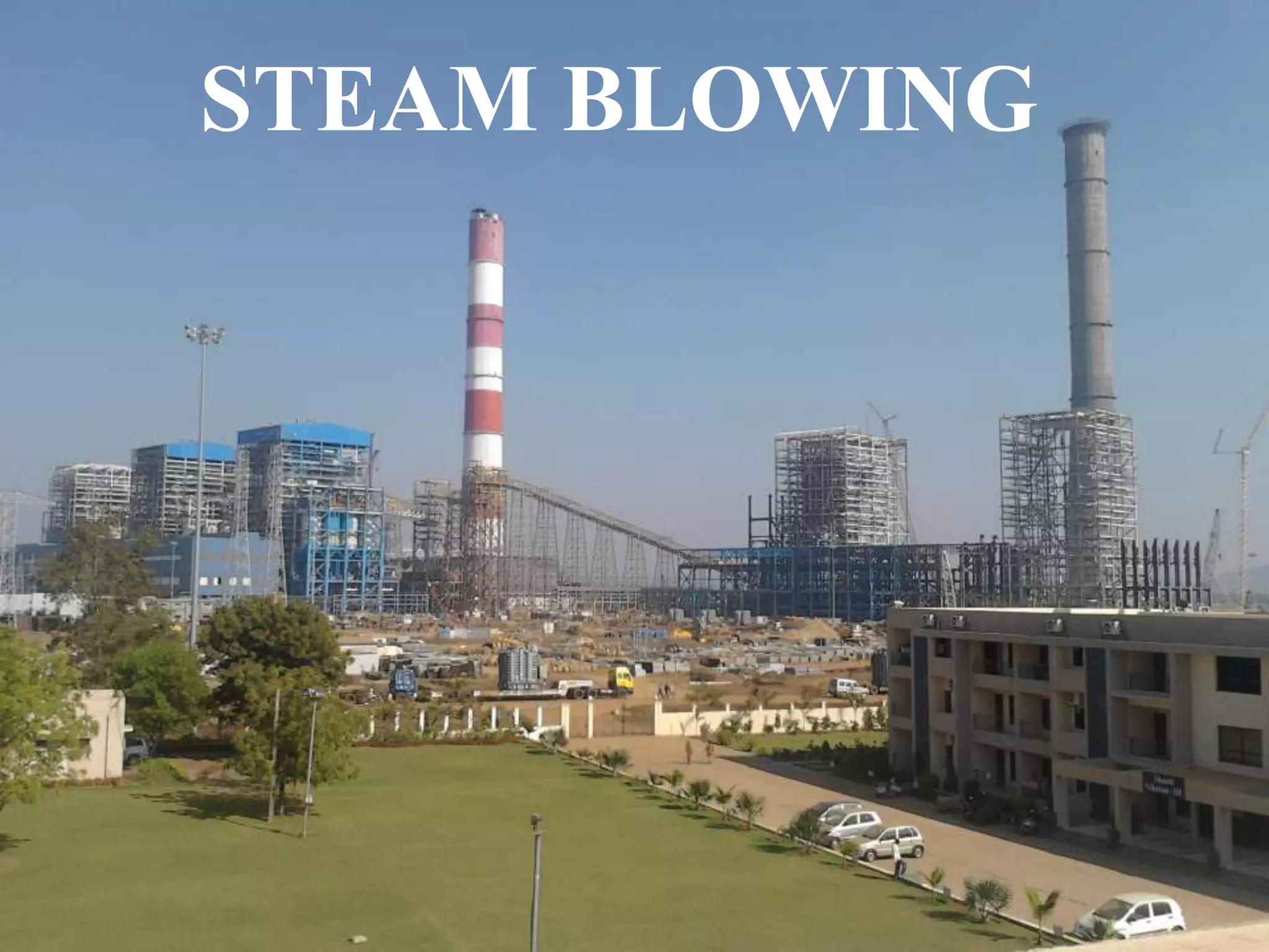
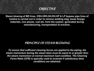
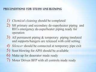
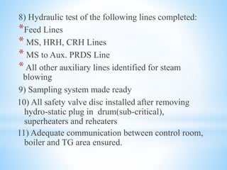
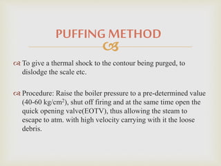
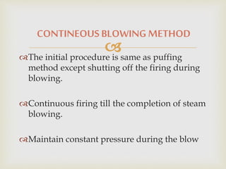
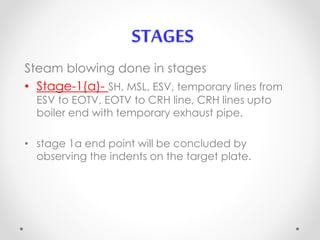
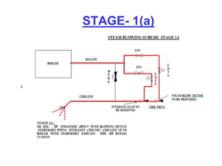
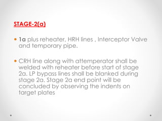
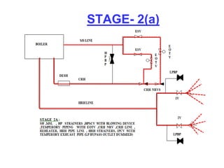
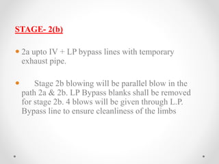
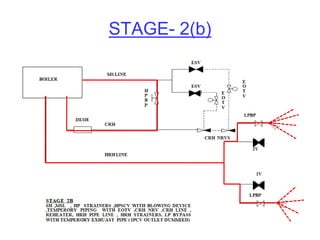
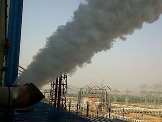
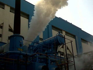
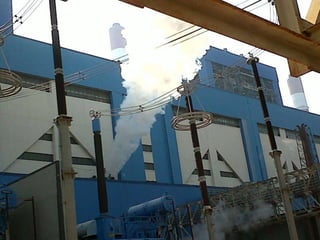
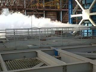
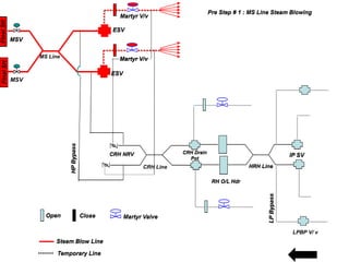
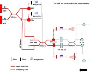
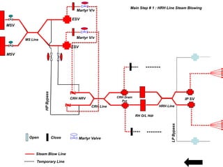
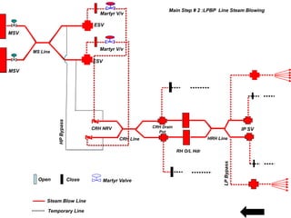
STEAM BLOWING
OBJECTIVE 
Steam blowing of MS lines, CRH,HRH,SH,RH,HP & LP bypass pipe lines of 
turbine is carried out in order to remove welding slag, loose foreign 
materials, iron pieces, rust etc. from the system, generated during 
manufacturing, transportation & erection. 
PRINCIPLE OF STEAM BLOWING 
To ensure that sufficient cleaning forces are applied to the piping, the 
steam momentum during the steam blow must be equal to or greater than 
the steam momentum at normal maximum load condition. The Cleaning 
Force Ratio (CFR) is typically used to evaluate if satisfactory blow 
conditions are obtained.
PRECONDITIONS FOR STEAM LINE BLOWING 
1) Chemical cleaning should be completed 
2) SH primary and secondary de-superheater piping and 
RH’s emergency de-superheater piping ready for 
operation 
3) All permanent piping & temporary piping insulated 
and supports/hangers are released with cold setting 
4) Silencer should be connected at temporary pipe exit 
5) Soot blowing for APH should be available 
6) Make up for deaerator made ready 
7) Motor Driven BFP with all controls made ready
8) Hydraulic test of the following lines completed: 
*Feed Lines 
* MS, HRH, CRH Lines 
* MS to Aux. PRDS Line 
* All other auxiliary lines identified for steam 
blowing 
9) Sampling system made ready 
10) All safety valve disc installed after removing 
hydro-static plug in drum(sub-critical), 
superheaters and reheaters 
11) Adequate communication between control room, 
boiler and TG area ensured.
12) Flow nozzle, control valves and NRV flaps wherever 
applicable should be not erected before steam blowing and 
suitable spool pieces are erected. Strainers in the path 
should be removed. 
13) Required number of Target Plates and holder made 
available
BASIC TECHNIQUE USED 
1) PUFFING METHOD 
2) PURGING METHOD / CONTINEOUS BLOW 
METHOD
PUFFING METHOD 
 
 To give a thermal shock to the contour being purged, to 
dislodge the scale etc. 
 Procedure: Raise the boiler pressure to a pre-determined value 
(40-60 kg/cm2), shut off firing and at the same time open the 
quick opening valve(EOTV), thus allowing the steam to 
escape to atm. with high velocity carrying with it the loose 
debris.
CONTINEOUS BLOWING METHOD 
 
The initial procedure is same as puffing 
method except shutting off the firing during 
blowing. 
Continuous firing till the completion of steam 
blowing. 
Maintain constant pressure during the blow
STAGES 
Steam blowing done in stages 
• Stage-1(a)- SH, MSL, ESV, temporary lines from 
ESV to EOTV, EOTV to CRH line, CRH lines upto 
boiler end with temporary exhaust pipe. 
• stage 1a end point will be concluded by 
observing the indents on the target plate.
STAGE- 1(a)
STAGE- 1(b) 
 SH,MSL, HP bypass inter connection, hand 
operated valve mounted in place of HP 
bypass valve and CRH lines upto Boiler end 
with temporary exhaust piping. 
 In this stage 6 to 8 blows will be given through 
HP bypass lines to ensure cleanliness of the 
limb. 
 EOTV will be kept closed. Manually Operated 
Isolation Valves in HP bypass lines will be kept 
opened fully.
STAGE- 1(b)
STAGE-2(a) 
 1a plus reheater, HRH lines , Interceptor Valve 
and temporary pipe. 
 CRH line along with attemperator shall be 
welded with reheater before start of stage 
2a. LP bypass lines shall be blanked during 
stage 2a. Stage 2a end point will be 
concluded by observing the indents on 
target plates
STAGE- 2(a)
STAGE- 2(b) 
 2a upto IV + LP bypass lines with temporary 
exhaust pipe. 
 Stage 2b blowing will be parallel blow in the 
path 2a & 2b. LP Bypass blanks shall be removed 
for stage 2b. 4 blows will be given through L.P. 
Bypass line to ensure cleanliness of the limbs
STAGE- 2(b)
TARGET PLATE 
• Generally Stainless steel panel 
• Target plate set at the first, sixth, ninth, twelfth purging, 
thereafter set target for each purging until purging results 
qualified . 
• Width about 8% of the steam vent tubes inner diameter(ID) 
and length equal to ID 
• Brinell hardness < 90 
• Steam velocity – 258 m/sec 
• Target plates to be introduced just before steam blowing / 
light up—to be removed soon after blowing is completed.
STEAM BLOWING COMPLETION CRITERIA 
• At least 2 continuous target plates should not have 
ORIFICE GRANULARITY on the target shall be not larger 
than 0.8 mm 
• No impacts with a diameter larger than 1 mm. 
• Not more than 4 impacts with a diameter larger than 0.5 
mm. 
• Not more than 10 impacts with a diameter of 0.2 to 0.5 mm 
.
Martyr V/v 
Martyr V/v 
CRH Line 
Final SH Final SH 
ESV 
ESV 
HP Bypass 
MS Line 
CRH NRV CRH Drain 
Pot 
RH O/L Hdr 
HRH Line 
MSV 
MSV 
LP Bypass 
IP SV 
Open Close Martyr Valve 
Steam Blow Line 
Temporary Line 
Pre Step # 1 : MS Line Steam Blowing 
LPBP V/ v
Final SH Final SH 
Martyr V/v 
ESV 
Martyr V/v 
ESV 
HP Bypass 
MS Line 
CRH NRV CRH Drain 
CRH Line 
Pot 
RH O/L Hdr 
HRH Line 
MSV 
MSV 
LP Bypass 
IP SV 
Open Close Martyr Valve 
Steam Blow Line 
Temporary Line 
Pre Step # 2 : HPBP / CRH Line Steam Blowing
Final SH Final SH 
Martyr V/v 
ESV 
Martyr V/v 
ESV 
HP Bypass 
MS Line 
CRH NRV CRH Drain 
CRH Line 
Pot 
RH O/L Hdr 
HRH Line 
MSV 
MSV 
LP Bypass 
IP SV 
Open Close Martyr Valve 
Steam Blow Line 
Temporary Line 
Main Step # 1 : HRH Line Steam Blowing
Final SH Final SH 
Martyr V/v 
ESV 
Martyr V/v 
ESV 
HP Bypass 
MS Line 
CRH NRV CRH Drain 
CRH Line 
Pot 
RH O/L Hdr 
HRH Line 
MSV 
MSV 
LP Bypass 
IP SV 
Open Close Martyr Valve 
Steam Blow Line 
Temporary Line 
Main Step # 2 :LPBP Line Steam Blowing
Steam blowing stages before turbine rolling

Steam blowing stages before turbine rolling

  • 1.
  • 2.
    OBJECTIVE Steam blowingof MS lines, CRH,HRH,SH,RH,HP & LP bypass pipe lines of turbine is carried out in order to remove welding slag, loose foreign materials, iron pieces, rust etc. from the system, generated during manufacturing, transportation & erection. PRINCIPLE OF STEAM BLOWING To ensure that sufficient cleaning forces are applied to the piping, the steam momentum during the steam blow must be equal to or greater than the steam momentum at normal maximum load condition. The Cleaning Force Ratio (CFR) is typically used to evaluate if satisfactory blow conditions are obtained.
  • 3.
    PRECONDITIONS FOR STEAMLINE BLOWING 1) Chemical cleaning should be completed 2) SH primary and secondary de-superheater piping and RH’s emergency de-superheater piping ready for operation 3) All permanent piping & temporary piping insulated and supports/hangers are released with cold setting 4) Silencer should be connected at temporary pipe exit 5) Soot blowing for APH should be available 6) Make up for deaerator made ready 7) Motor Driven BFP with all controls made ready
  • 4.
    8) Hydraulic testof the following lines completed: *Feed Lines * MS, HRH, CRH Lines * MS to Aux. PRDS Line * All other auxiliary lines identified for steam blowing 9) Sampling system made ready 10) All safety valve disc installed after removing hydro-static plug in drum(sub-critical), superheaters and reheaters 11) Adequate communication between control room, boiler and TG area ensured.
  • 5.
    12) Flow nozzle,control valves and NRV flaps wherever applicable should be not erected before steam blowing and suitable spool pieces are erected. Strainers in the path should be removed. 13) Required number of Target Plates and holder made available
  • 6.
    BASIC TECHNIQUE USED 1) PUFFING METHOD 2) PURGING METHOD / CONTINEOUS BLOW METHOD
  • 7.
    PUFFING METHOD   To give a thermal shock to the contour being purged, to dislodge the scale etc.  Procedure: Raise the boiler pressure to a pre-determined value (40-60 kg/cm2), shut off firing and at the same time open the quick opening valve(EOTV), thus allowing the steam to escape to atm. with high velocity carrying with it the loose debris.
  • 8.
    CONTINEOUS BLOWING METHOD  The initial procedure is same as puffing method except shutting off the firing during blowing. Continuous firing till the completion of steam blowing. Maintain constant pressure during the blow
  • 9.
    STAGES Steam blowingdone in stages • Stage-1(a)- SH, MSL, ESV, temporary lines from ESV to EOTV, EOTV to CRH line, CRH lines upto boiler end with temporary exhaust pipe. • stage 1a end point will be concluded by observing the indents on the target plate.
  • 10.
  • 11.
    STAGE- 1(b) SH,MSL, HP bypass inter connection, hand operated valve mounted in place of HP bypass valve and CRH lines upto Boiler end with temporary exhaust piping.  In this stage 6 to 8 blows will be given through HP bypass lines to ensure cleanliness of the limb.  EOTV will be kept closed. Manually Operated Isolation Valves in HP bypass lines will be kept opened fully.
  • 12.
  • 13.
    STAGE-2(a)  1aplus reheater, HRH lines , Interceptor Valve and temporary pipe.  CRH line along with attemperator shall be welded with reheater before start of stage 2a. LP bypass lines shall be blanked during stage 2a. Stage 2a end point will be concluded by observing the indents on target plates
  • 14.
  • 15.
    STAGE- 2(b) 2a upto IV + LP bypass lines with temporary exhaust pipe.  Stage 2b blowing will be parallel blow in the path 2a & 2b. LP Bypass blanks shall be removed for stage 2b. 4 blows will be given through L.P. Bypass line to ensure cleanliness of the limbs
  • 16.
  • 17.
    TARGET PLATE •Generally Stainless steel panel • Target plate set at the first, sixth, ninth, twelfth purging, thereafter set target for each purging until purging results qualified . • Width about 8% of the steam vent tubes inner diameter(ID) and length equal to ID • Brinell hardness < 90 • Steam velocity – 258 m/sec • Target plates to be introduced just before steam blowing / light up—to be removed soon after blowing is completed.
  • 18.
    STEAM BLOWING COMPLETIONCRITERIA • At least 2 continuous target plates should not have ORIFICE GRANULARITY on the target shall be not larger than 0.8 mm • No impacts with a diameter larger than 1 mm. • Not more than 4 impacts with a diameter larger than 0.5 mm. • Not more than 10 impacts with a diameter of 0.2 to 0.5 mm .
  • 23.
    Martyr V/v MartyrV/v CRH Line Final SH Final SH ESV ESV HP Bypass MS Line CRH NRV CRH Drain Pot RH O/L Hdr HRH Line MSV MSV LP Bypass IP SV Open Close Martyr Valve Steam Blow Line Temporary Line Pre Step # 1 : MS Line Steam Blowing LPBP V/ v
  • 24.
    Final SH FinalSH Martyr V/v ESV Martyr V/v ESV HP Bypass MS Line CRH NRV CRH Drain CRH Line Pot RH O/L Hdr HRH Line MSV MSV LP Bypass IP SV Open Close Martyr Valve Steam Blow Line Temporary Line Pre Step # 2 : HPBP / CRH Line Steam Blowing
  • 25.
    Final SH FinalSH Martyr V/v ESV Martyr V/v ESV HP Bypass MS Line CRH NRV CRH Drain CRH Line Pot RH O/L Hdr HRH Line MSV MSV LP Bypass IP SV Open Close Martyr Valve Steam Blow Line Temporary Line Main Step # 1 : HRH Line Steam Blowing
  • 26.
    Final SH FinalSH Martyr V/v ESV Martyr V/v ESV HP Bypass MS Line CRH NRV CRH Drain CRH Line Pot RH O/L Hdr HRH Line MSV MSV LP Bypass IP SV Open Close Martyr Valve Steam Blow Line Temporary Line Main Step # 2 :LPBP Line Steam Blowing