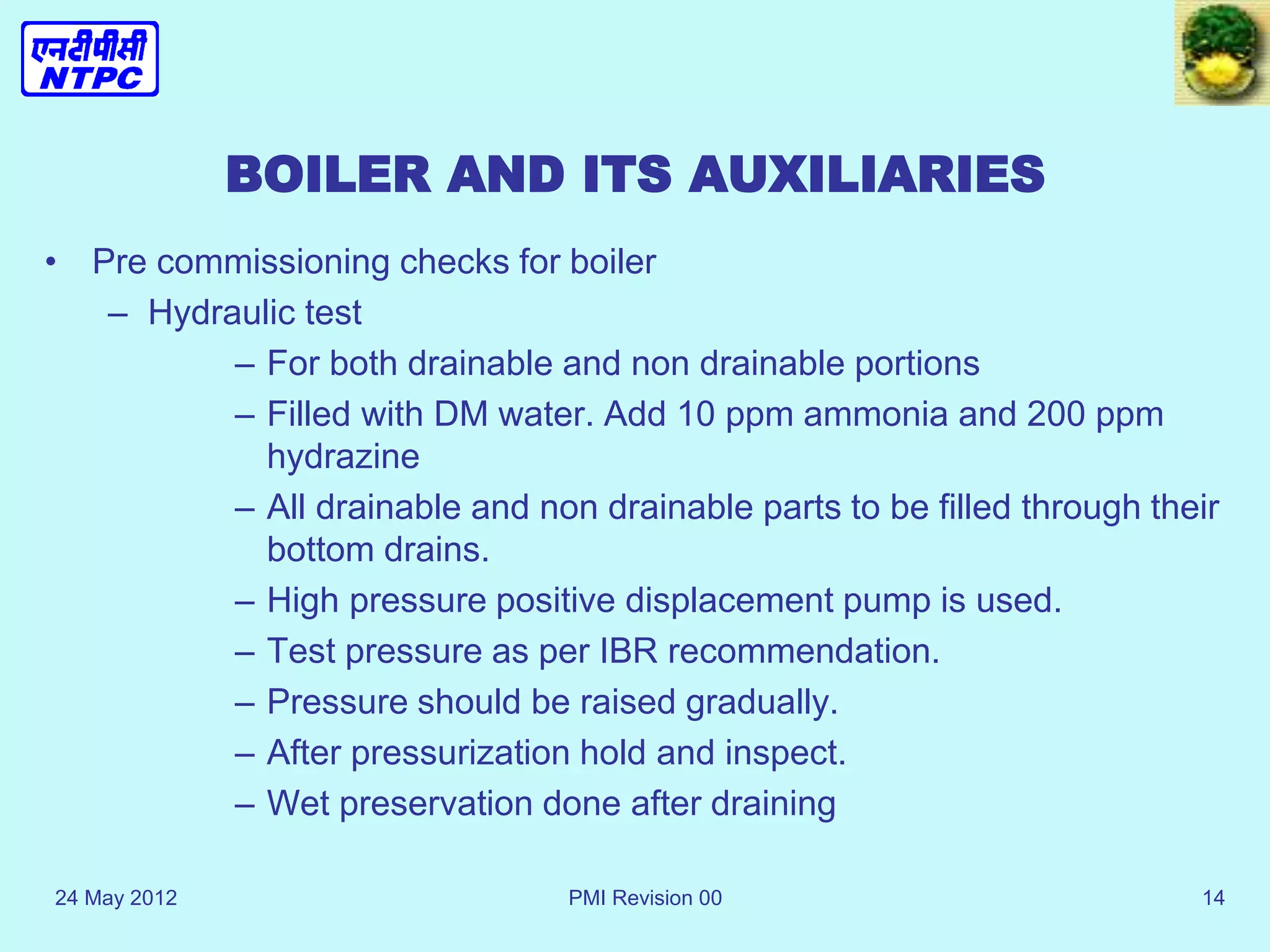
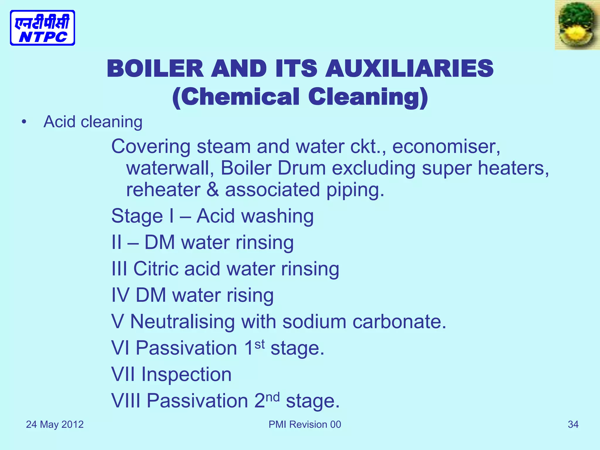
SlideShare a Scribd company logo
1 of 80
Download to read offline
24 May 2012 PMI Revision 00 1
BOILER
COMMISSIONING
24 May 2012 PMI Revision 00 2
BOILER AND AUX. COMMISSIONING
COMMISSIONING :It is the later stage of
erection and starting stage of operation.
It includes 14 days of continuous
operation with 72 hrs of full load operation.
24 May 2012 PMI Revision 00 3
INTRODUCTION TO COMMISSIONING
• Commissioning – Activities before taking over a
plant.
• Purpose
– To check that plant is supplied as per design
– Quality of erection and commissioning
– Plant operates reliably, safety & design
performance.
– Finding out reason for any failure to achieve the
design performance.
24 May 2012 PMI Revision 00 4
INTRODUCTION TO COMMISSIONING
• Organization
– Steering committee – Policy and priorites.
Ensures adequate resource. Approval of
documents. – Headed by G.M.
– Commissioning panel – Control & progress of
day to day activities. Coordination between
Test teams and Working groups. Erection &
O&M dept.
– Working groups – Looks after requirement of
Test team.
– Test Team – Conducting testing &
commissioning.
24 May 2012 PMI Revision 00 5
INTRODUCTION TO COMMISSIONING
• Documentation
1. Papers of principle – Prepared jointly by
Erection and corporate O.S.
• To set out principles & objectives
• Established design data to compare
plant.
• Define documentation requirement
24 May 2012 PMI Revision 00 6
INTRODUCTION TO COMMISSIONING
• Documentation
2. Testing & commissioning Schedule
• To meet the requirement of the paper of
principle
• Plant under cover
• Detail test method & programme
• Safety
• Emergencies
• Individual responsibility
• Results
24 May 2012 PMI Revision 00 7
INTRODUCTION TO COMMISSIONING
• Documentation
3. Standard checklist
• Ensuring completion of erection
• Limited extent operation
• Test conductance in consistent
manner
• Instrument providing Schedule with
range & resolution and calibration
validation.
24 May 2012 PMI Revision 00 8
INTRODUCTION TO COMMISSIONING
• Documentation
4. Design change notification
5. Test reports
Recording of result
Omission report
Analysis
6. Safety procedure
7. Plant certification
Safety clearance certificate
Record of initial operation
Clearance for station operation certificate
Initial taking over certificate
Final internal contract clearance – completion of guarantee
period
8. Plant completion report. – PG test evaluation and acceptance
24 May 2012 PMI Revision 00 9
---------------------------------------------------------------------------------------------------------------------
MECHANICAL
--------------------------------------------------------------------------------------------------------------------
STATION STANDARD CHECK LIST SHEET 1 OF2
---------------------------------------------------------------------------------------------------------------------
PLANT ITEM PIPEWORK-CONSTANT LOAD SUPPORT
---------------------------------------------------------------------------------------------------------------------
PLANT NOMENCLATURE
SYSTEM -----------------------------------------------------
MANUFACTURER--------------------------- SRL. NO.---------------------------------------------------
LOCATION-----------------------------------------------------------------------------------------------------
NO ACTIVITY WITNESSED Date
--------------------------
NTPC CONTR
1.General conditions satisfy the Site standing Instructions as listed In the “Plant Item
Commissioning Essential Pre –requisites”(SCL MS1/1)
2.The name plate legend agrees with the approved NTPC plant Nomenclature is clearly visible
securely fixed, durable and correlates with remote labels.
3.The installation is complete and correct in accordance with the latest drawing and
specification and support attachments to building Steel work and pipework are secure and
satisfactory.
4.Access for adjustments maintenance and repairs is a satisfactory,
5.Check that support-setting details can be easily read.
REMARKS
---------------------------------------------------------------------------------------------------------------------
SCL REF: M/4/6
24 May 2012 PMI Revision 00 10
-------------------------------------------------------------------------------------------------------------------
CONTROL & INSTRUMENTATION
---------------------------------------------------------------------------------------------------------------------
STATION TEST PROCEDURE SHEET 1 OF 2
---------------------------------------------------------------------------------------------------------------------INSTRUMENTS: PRESSURE GUAGE
TP REF: 1.5.1.
---------------------------------------------------------------------------------------------------------------------
---------------------------------------------------------------------------------------------------------------------
NTPC TAG NO UNIT
---------------------------------------------------------------------------------------------------------------------
---------------------------------------------------------------------------------------------------------------------
No. Activity
Remarks
---------------------------------------------------------------------------------------------------------------------
1.Test Equipments Required.
1.1Portable Dead Weight Tester, Comparator. Or other similar sure of the vacuum source.
1.2Standard Test gauge if not using a dead weight tester, other standard pressure vacuum gauge, dependent on
the range of the instrument being tested.
2.Check calibration of the test Equipment.
3.Check the gauge calibration over its entire range 20% steps, increasing and decreasing, Allow for head
correction where necessary, Note the results on Standard Calibration sheet 1.15.1.
4.Recheck the calibration of the test equipment.
5.Acceptable errors for pressure gauges, unless otherwise specified in the contract specification are:-
Standard of Test gauges +_ 0.25% FSD.
---------------------------------------------------------------------------------------------------------------------
DEFECTS & OMISSIONS CONTINUATION OVERLEAF
---------------------------------------------------------------------------------------------------------------------
REMARKS
---------------------------------------------------------------------------------------------------------------------NTPC SIGNATURE
CONTRACTORS SIGNATURE DATE
---------------------------------------------------------------------------------------------------------------------
24 May 2012 PMI Revision 00 11
BOILER AND ITS AUXILIARIES
• Steps
– Pre-commissioning checks
– Trial run of equipments
e.g. Fans and APH commissioning
– Hydraulic Test
– Chemical cleaning
– Gas Tightness Test
– ESP commng.
– Fuel Oil System
– Preparation for first light-up
– Steam blowing
– Safety v/v settings
– Other boiler Aux. commissioning
24 May 2012 PMI Revision 00 12
BOILER AND ITS AUXILIARIES
• Pre commissioning checks
– Physical inspection
– Ensuring tightness
– Lubrication check
– Setting of relief v/v
– Operation test on v/vs and fittings
– Insulation test on cable/ motor
– Rotation checks
– Flushing out the oil system
– Trial run of motor with all protection for 8 hrs
– Coupling of fan with motor
24 May 2012 PMI Revision 00 13
BOILER AND ITS AUXILIARIES
• Trial run of equipments
– Commissioning checks
– Checking of IGV/ pitch control mechanism
– Operation of lub oil pump system
– Operation of Discharge damper
– Starting the fan as recommended by mfd.
– 8 hrs trial run conductance
– Logging parameters.
24 May 2012 PMI Revision 00 14
BOILER AND ITS AUXILIARIES
• Pre commissioning checks for boiler
– Hydraulic test
– For both drainable and non drainable portions
– Filled with DM water. Add 10 ppm ammonia and 200 ppm
hydrazine
– All drainable and non drainable parts to be filled through their
bottom drains.
– High pressure positive displacement pump is used.
– Test pressure as per IBR recommendation.
– Pressure should be raised gradually.
– After pressurization hold and inspect.
– Wet preservation done after draining
24 May 2012 PMI Revision 00 15
24 May 2012 PMI Revision 00 16
BOILER HYDRAULIC TEST
24 May 2012 PMI Revision 00 17
CHEMICALS REQUIREMENT
24 May 2012 PMI Revision 00 18
24 May 2012 PMI Revision 00 19
24 May 2012 PMI Revision 00 20
24 May 2012 PMI Revision 00 21
24 May 2012 PMI Revision 00 22
BOILER AND ITS AUXILIARIES
• Pre commissioning checks for boiler
– Gas tightness check
– Through smoke generator. 24 MKS,40 IBS wt.
from defance store.
– Run FD and ID.
24 May 2012 PMI Revision 00 23
24 May 2012 PMI Revision 00 24
24 May 2012 PMI Revision 00 25
AIR AND GAS TIGHTNESS TEST OF
FURNACE AND DUCTS
STAGE 1 : FD fan to air inlet damper of APH – 300
mmWC
STAGE II : APH inlet damper to wind box. - 300
mmWC
STAGE III : Wind box to APH gas O/L damper. - 75
mmWC
STAGE IV : APH O/L damper to ESP I/L gate. - 300
mmWC
24 May 2012 PMI Revision 00 26
AIR AND GAS TIGHTNESS TEST OF
FURNACE AND DUCTS
STAGE V : ESP O/L damper to ID fan I/L damper - 300
mmWC
STAGE VI : ID fan I/L damper to stack. – kerosene test.
STAGE VII : PA fan to PAPH I/L damper. (SCAPH bypass,
cold air duct and seal air pipes. - 500 mmWC
STAGE VIII : PAPH air I./L to hot air gates – 500 mmWC
ESP is tested by air in leak test.
24 May 2012 PMI Revision 00 27
AIR AND GAS TIGHTNESS TEST OF
FURNACE AND DUCTS
ALL DAMPERS ARE TO BE SEALED.
NMEJ’s ARE TO BE ERECTED.
NO INSULATION OVER THE DUCT.
ALL AIR LEAKS ARE TO BE CHECKED BY SOAP SOLUTION.
BAH GATES AND SEAL TROUGH ARE TO BE CLOSED.
MANOMETERS ARE TO BE PROVIDED TO NOTE THE PRESSURE.
24 May 2012 PMI Revision 00 28
PROTOCOL ON SMOKE GENERATOR TEST
OF THE BOILER
Name of the site:
Unit NO:
The smoke generator test was carried out on the procedure to detect and rectify the leaking
portions in the systems. The leakage found has been rectified. Details of the No. of smoke
generators used indifferent sections are given below.
---------------------------------------------------------------------------------------------------------------------
Date Section No. Of Smoke
Remarks
Generators
used
---------------------------------------------------------------------------------------------------------------------
Cold Air duct
Hot Air
Second Pass
Furnace
--------------------------------------------------------------------------------------------------------------------
EP LEFT
EP RIGHT
---------------------------------------------------------------------------------------------------------------------
Leakages found during the test were rectified and wherever necessary a repeat test was done.
CUSTOMER CONSULTNT
24 May 2012 PMI Revision 00 29
BOILER AND ITS AUXILIARIES
• ESP commissioning
– Physical inspection.
– Electrical inspection
– Gas distribution test
– Air load test
24 May 2012 PMI Revision 00 30
BOILER AND ITS AUXILIARIES
• Fuel oil system
– Physical inspection.
– Flushing of lines.
– Trial of pumps.
– Ignitor and burner housing check.
24 May 2012 PMI Revision 00 31
BOILER AND ITS AUXILIARIES
(Chemical Cleaning)
• Alkali boil-out
– Purpose: Chemical cleaning of boiler water & steam
system to remove loose foreign material, oil, grease etc.
– Water Washing – Temporary water filled arrangement. It
continues till conductivity of inlet/ outlet water equals.
– Process continued nos. of time till conductivity of
washing water matches with fresh filtered water.
24 May 2012 PMI Revision 00 32
BOILER AND ITS AUXILIARIES
(Chemical Cleaning)
• Alkali boil-out
– Alkali boil out – Fill water with DM water. Add Trisodium phosphate
(1000 PPM 0.1%), Do Decca Hydrate & Hydrazine Hydrate (200
PPM 0.02 %)
– Filling upto 180 mm.
– Boiler light up with AB elevation
– Pressure raised to 40 Kg/ Cm2.
– Hourly blow down given to remove impurities and feeding maintain to
keep drum level.
– Oil gun to cut out during blowing
– Boiler expansion noted
– At the end boiler will be boxed up and hot draining done when pr.is
1.5 Kg./Cm2.
24 May 2012 PMI Revision 00 33
COMMISSIONING PROTOCOL FOR ALKALI BOIL OUT
PROJECT------------------------------------------- CONTRACT NO ----------------------------------
UNIT NO ------------------------------ RATING ------------------------ MW. CUSTOMER----
Alkali Boil Out Boiler was carried out from------------------------------------------------------(date)
To-------------------------------------------(Date).
The following chemicals were changed:
TRISODIUM PHOSPHATE --------- Kgs (--------- ppm).
The boil out was carried out at 40-kg/cm2 pressures for a period of -----------------------------
Hence and the process was declared completed-------------------------------------------- -------at ----------------------
------------- Hrs----------------------------(date).
The end point values are as follows:
-------------------------------------------------
Ph po4 ppm Oil ppm
-------------------------------------------------------------------------------------------------------------
REMARKS:
-------------------------------------------------------------------------------------------------------------
Manufacturer Customer Engineer
24 May 2012 PMI Revision 00 34
BOILER AND ITS AUXILIARIES
(Chemical Cleaning)
• Acid cleaning
Covering steam and water ckt., economiser,
waterwall, Boiler Drum excluding super heaters,
reheater & associated piping.
Stage I – Acid washing
II – DM water rinsing
III Citric acid water rinsing
IV DM water rising
V Neutralising with sodium carbonate.
VI Passivation 1st stage.
VII Inspection
VIII Passivation 2nd stage.
24 May 2012 PMI Revision 00 35
BOILER AND ITS AUXILIARIES
(Chemical Cleaning)
• Acid cleaning
HCL 4-6 % conc.
Ammonia Bifluoride 1%
Rodine 213 special 0.1 % inhibitor.
Lime
Nitrogen Gas capping arrangement.
Removal of Drum internals
Down comer fitted with orifice. Sup heater steam
opening at drum to be plugged by rubber stamp.
S/H to be kept pressurised at 5 Kg/Cm2 with
hydrazine.
24 May 2012 PMI Revision 00 36
BOILER AND ITS AUXILIARIES
(Chemical Cleaning)
• Acid cleaning procedure
– Fill boiler with water and a circulation flow of 400
t/Hr is maintained.
– Heat water to 65 deg cen. With steam.
– Inhibitor charged and half quantity of ammonia
bifluoride.
– When the above mixture get dissolved, start acid
dosing.
– Concentration should not exceed 6 %.
– Temp. is maintained below 70 Deg.
– HCL and Iron Conc. Intially goes high then comes
down and became steady.
– Constant value of HCL and iron conc. Denote
completion of acid washing.
– Cleaning soln. drained through neutralising pit.
24 May 2012 PMI Revision 00 37
BOILER AND ITS AUXILIARIES
(Chemical Cleaning)
• Rinsing with water.
–System filled with water
–Temp. raised to 65 Deg.
–Water circulation continue.
–Water is dump under nitrogen capping.
24 May 2012 PMI Revision 00 38
BOILER AND ITS AUXILIARIES
(Chemical Cleaning)
• Citric acid rinsing.
–System filled with water
–Temp. raised to 65 Deg.
–Citric acid 0.2 % by weight.
–Water is recirculated
–When inlet outlet sample matches then
declare over
–Water is dump under nitrogen capping.
24 May 2012 PMI Revision 00 39
BOILER AND ITS AUXILIARIES
(Chemical Cleaning)
• Neutralisation.
–System filled with water
–Temp. raised to 80 Deg.
–Sodium Carbonate 1 %..
–Water is recirculated
–When inlet outlet sample matches then
declare over
–Water is dump under nitrogen capping.
24 May 2012 PMI Revision 00 40
BOILER AND ITS AUXILIARIES
(Chemical Cleaning)
• Passivation 1st stage.
– Purpose – building uniform layer of Magnetite on
bare surface obtained after acid cleaning.
– System filled with water
– Temp. raised to 85 Deg.
– 300 ppm Hydrazine (9.6 pH)
– Water is recirculated
– Maintain hydrazine concentration to 150 ppm.
– When inlet outlet sample matches then declare
over
– Water is dump under atmospheric capping.
24 May 2012 PMI Revision 00 41
BOILER AND ITS AUXILIARIES
(Chemical Cleaning)
• Passivation 2nd stage.
– Purpose – building uniform layer of Magnetite on
bare surface obtained after acid cleaning.
– System filled with water
– Temp. raised to 85 Deg.
– 300 ppm Hydrazine (9.6 pH)
– Boiler lighted up. 40 Kg pr. Raised. Maintain for 20
Hrs.
– Maintain hydrazine concentration to 150 ppm.
– Hot drain at 90 deg.
– Water is dump under atmospheric capping.
24 May 2012 PMI Revision 00 42
STEAM BLOWING
OF
BOILER AND
ASSOCIATED STEAM LINE
INCLUDING
AUXILIARY STEAM LINES
24 May 2012 PMI Revision 00 43
CLICK ON THE STAGE TO SEE THE ANIMATION
• THEORY OF STEAM BLOWING
• SCHEME OF STEAM BLOWING
• STAGE-1 STEAM BLOWING (SH,M.S LINE UP TO ESV)
• STAGE-2A STEAM BLOWING (SH,M.S, CRH LINE)
• STAGE-2B STEAN BLOWING (SH,MS,HRH&CRH UP TO DESH)
• STAGE-3A STEAM BLOWING (SH, MS, CRH, RH, HRH, UP TO IV)
• STAGE-3B STEAM BLOWING (SH, MS, CRH, RH, HRH & LPBP )
• STAGE-4A STEAM BLOWING (EXTRN TO BFPDT-A, FROM CRH)
• STAGE-4B STEAM BLOWING (EXTRN TO BFPDT-B, FROM CRH)
CLICK / ENTER, AFTER EVERY EVENT IN THE SCHEME TO SEE THE
SEQUENCE OF EVENTS
24 May 2012 PMI Revision 00 44
STEAM BLOWING
• OBJECTIVE: PURPOSE OF STEAM BLOWING IS TO REMOVE
SCALES, LOOSE MATERIAL, IRON CUTTINGS etc. THAT MIGHT HAVE
BEEN ENTRAPPED IN S.H, STEAM PIPING, REHEATERS DURING
MANUFACTURE.
• TECHNIQUE: STEAM BLOWING IS CARRIED OUT BY PUFFING
METHOD.THIS TECHNIQUE WILL GIVE A THERMAL SHOCK TO THE
CONTOUR BEING PURGED TO DISLODGE THE SCALES etc. WHICH WILL
SUBSEQUENTLY BE REMOVED BY EXPANDING STEAM.
• PROCEDURE: FOR BLOWING THE STEAM, RAISE THE BOILER DRUM
PRESSURE UPTO 40 TO 50 Ksc; SHUT OFF BOILER FIRING AND OPEN
THE ELECTRICALLY OPERATED TEMPORARY VALVES (EOTVs) / BOILER
M.S. STOP VALVES AS SHOWN IN THE FOLLOWING SCHEMES.
– DRUM LEVEL SHOULD BE MAINTAINED AT LOWEST PORT (VISIBLE
LIMIT) BEFORE THE START OF EACH BLOW TO AVOID WATER
DROPLETS CARRYOVER TO THE SATURATED STEAM PIPING.
– NUMBER OF BLOWS PER DAY ARE LIMITED TO 8 WITH AN INTERVAL
OF 1 ½ Hrs.FOR COOLING IN ADDITION TO OVER NIGHT COOLING
• SCHEME: STEAM BLOWING IS DONE IN SEVEN STAGES AS
DESCRIBED IN THE FOLLOWING SLIDES.
BACK TO
INDEX
24 May 2012 45
LPBP V/V
LPBP V/V
TO CONDENSER
HRH LINE
R
H
I
H
D
R
R
H
O
H
D
R
S
H
I
H
S
H
O
H
MS STOP V/V
M
S
L
ESV
ESV
C
R
H
N
R
V
EOTV
CRH LINE
HPBP SPOOL
PIECE 450
THRO / BLANK
FLANGE
D
E
S
H
EOTV
A
A
B B
C
C
D
D
E
E
STEAM BLOWING SCHEME
--THRO / BLANK FLANGE
--TARGET PLATE
-- OPEN INDICATION
-- CLOSE INDICATION
-- R.H & HRH LINE
-- LPBP LINE
-- S.H & MS LINE
-- CRH & HPBP
-- TEMPORARY PIPING
-- PERMANENT PIPING
--UN TREATED PIPE
HPBP LINE
EOTV– ELECTRICALLY OPERATED
………TEMPORARY VALVE
HOTV’’s
HOTV–-HAND OPERATED
………TEMPORARY VALVE
BACK TO
INDEX
24 May 2012 PMI Revision 00 46
LPBP V/V
LPBP V/V
TO CONDENSER
HRH LINE
R
H
I
H
D
R
R
H
O
H
D
R
S
H
I
H
S
H
O
H
MS STOP V/V
M
S
L
ESV
ESV
C
R
H
N
R
V
CRH LINE
HPBP SPOOL
PIECE 450
THRO / BLANK
FLANGE
D
E
S
H
EOTV
--THRO / BLANK FLANGE
A
A
C
B
B
D
D
E
E
--TARGET PLATE
STAGE-I
-- OPEN
-- CLOSE
-- R.H & HRH
-- LPBP
-- S.H & MS LINE
-- CRH & HPBP
-- TEMPORARY PIPING
-- PERMANENT PIPING
--UN TREATED PIPE
MS STOP VALVES IN
OPEN CONDITION
FLANGES "B”,"C”,"D”&"E”
ARE BLANKED, "A” IS
OPENED
STEAM BLOWING IS TO BE
CARRIED OUT USING EOTV’S
C
BLOW OFF V/V OPENED AT 50
Ksc & CLOSED AT 25 Ksc
DRUM PRESSURE
STAGE-1 COVERS SUPER
HEATERS & MS LINE UP TO
ESV
EOTV
HPBP LINE
HOTV’’s
BACK TO
INDEX
24 May 2012 PMI Revision 00 47
LPBP V/V
LPBP V/V
TO CONDENSER
HRH LINE
R
H
I
H
D
R
R
H
O
H
D
R
S
H
I
H
S
H
O
H
MS STOP V/V
M
S
L
ESV
ESV
C
R
H
N
R
V
CRH LINE
HPBP SPOOL
PIECE 450
THRO / BLANK
FLANGE
D
E
S
H
EOTV
A
A
C
C
B
B
D
D
E
E
STAGE-IIA
--THRO / BLANK FLANGE
--TARGET PLATE
-- OPEN
-- CLOSE
-- R.H & HRH
-- LPBP
-- S.H & MS LINE
-- CRH & HPBP
-- TEMPORARY PIPING
-- PERMANENT PIPING
--UN TREATED PIPE
MS STOP VALVES IN
OPEN CONDITION
FLANGES “A”,“B”,"D”&"E”
ARE BLANKED, “C” IS
OPENED
STEAM BLOWING IS TO BE
CARRIED OUT USING EOTV’S
SUGGESTED BLOWING
PRESSURE IS FROM 50KscTO
25 Ksc
STAGE-2 COVERS S.H, MS
LINE,JUMPER CONNECTING
ESV & CRH LINE
DESH IN CRH LINE IS NOT TO
BE ERECTED
JUMPER LINE CONN. TO CRH IS
TO BE TAKEN AFTER EOTVs
INSTALLED FOR STAGE-1
EOTV
HPBP LINE
HOTV’’s
BACK TO
INDEX
24 May 2012 PMI Revision 00 48
LPBP V/V
LPBP V/V
TO CONDENSER
HRH LINE
R
H
I
H
D
R
R
H
O
H
D
R
S
H
I
H
S
H
O
H
MS STOP V/V
M
S
L
ESV
ESV
C
R
H
N
R
V
CRH LINE
HPBP SPOOL
PIECE 450
THRO / BLANK
FLANGE
D
E
S
H
EOTV
A
A
C
C
B
B
D
D
E
E
STAGE-IIB
--THRO / BLANK FLANGE
--TARGET PLATE
-- OPEN
-- CLOSE
-- R.H & HRH
-- LPBP
-- S.H & MS LINE
-- CRH & HPBP
-- TEMPORARY PIPING
-- PERMANENT PIPING
--UN TREATED PIPE
EOTVs ARE IN CLOSED
CONDITION
FLANGES “A”,"D”&"E” ARE
BLANKED, “B”&“C” ARE
OPENED
STEAM BLOWING IS TO BE
CARRIED OUT USING MS
STOP VALVES
STAGE-2B COVERS S.H, MS
LINE,H.P BYPASS LINE& CRH
LINE
DESH IN CRH LINE IS NOT TO
BE ERECTED
EOTV
HPBP LINE
HOTV’’s
BACK TO
INDEX
24 May 2012 PMI Revision 00 49
LPBP V/V
LPBP V/V
TO CONDENSER
HRH LINE
R
H
I
H
D
R
R
H
O
H
D
R
S
H
I
H
S
H
O
H
MS STOP V/V
M
S
L
ESV
ESV
C
R
H
N
R
V
CRH LINE
HPBP SPOOL
PIECE 450
THRO / BLANK
FLANGE
D
E
S
H
EOTV
A
A
C
C
B
B
D
D
E
E
STAGE-IIIA
--THRO / BLANK FLANGE
--TARGET PLATE
-- OPEN
-- CLOSE
-- R.H & HRH
-- LPBP
-- S.H & MS LINE
-- CRH & HPBP
-- TEMPORARY PIPING
-- PERMANENT PIPING
--UN TREATED PIPE
MS STOP VALVES ARE
IN OPEN CONDITION
FLANGES “A”,“B”&"E” ARE
BLANKED, “C”&“D” ARE
OPENED
STEAM BLOWING IS TO BE
CARRIED OUT USING EOTVs
STAGE-3A COVERS S.H, MS
LINE,JUMPER CONNG. ESV
&CRH LINE,CRHLINE,R.H,HRH
DESH IN CRH LINE CAN BE
ERECTED
SUGGESTED BLOWING
PRESSURE IS 50 KscTO 25Ksc
EOTV
HPBP LINE
HOTV’’s
BACK TO
INDEX
24 May 2012 PMI Revision 00 50
LPBP V/V
LPBP V/V
TO CONDENSER
HRH LINE
R
H
I
H
D
R
R
H
O
H
D
R
S
H
I
H
S
H
O
H
MS STOP V/V
M
S
L
ESV
ESV
C
R
H
N
R
V
CRH LINE
HPBP SPOOL
PIECE 450
THRO / BLANK
FLANGE
D
E
S
H
EOTV
A
A
C
C
B
B
D
D
E
E
STAGE-IIIB
--THRO / BLANK FLANGE
--TARGET PLATE
-- OPEN
-- CLOSE
-- R.H & HRH
-- LPBP
-- S.H & MS LINE
-- CRH & HPBP
-- TEMPORARY PIPING
-- PERMANENT PIPING
--UN TREATED PIPE
MS STOP VALVES IN
OPEN CONDITION
FLANGES “A”,“B”&"D” ARE
BLANKED, “C”,"E” ARE
OPENED
STEAM BLOWING IS TO BE
CARRIED OUT USING EOTV’S
STAGE-3B COVERS S.H, MS
LINE,JUMPER CONNG.ESV &
CRH,CRH LINE,R.H,HRH,LPBP
DESH IN CRH LINE CAN BE
ERECTED
EOTV
HPBP LINE
HOTV’’s
BACK TO
INDEX
24 May 2012 PMI Revision 00 51
STAGE-IV A
FROM CRH
NEAR DEAERATOR
FROM IP / LP CROSS
AROUND TO DEAERATOR
FROM CROSS
AROUND PIPES
FROM IP / LP CROSS
AROUND PIPE
FROM APRDS
HEADER TDBFP-A TDBFP-B
CRH-1 CRH-3
CRH-2 CRH-4
BACK TO
INDEX
24 May 2012 PMI Revision 00 52
STAGE-IV B
NEAR DEAERATOR
FROM CRH
FROM IP / LP CROSS
AROUND TO DEAERATOR
FROM CROSS
AROUND PIPES
FROM IP / LP CROSS
AROUND PIPE
FROM APRDS
HEADER TDBFP-A TDBFP-B
CRH-1
CRH-3
CRH-2
CRH-4
BACK TO
INDEX
24 May 2012 53
COMMISSIONING
OF FANS
AIRPREHEATERS
24 May 2012 PMI Revision 00 54
COMMSSIONING OF LUB OIL
SYSTEM
• HYDROTEST OF LUB OIL LINES.
• HYDROTEST OF COOLERS.
• ACID CLEANING OF LUB OIL LINES.
• TRIAL RUN LUB OIL MOTORS.
• OIL FILLING
• LUB OIL FLUSHING.
• CONNECTION OF LUB OIL LINES.
24 May 2012 PMI Revision 00 55
ACID CLEANING.
1.DM WATER FLUSHING FOR 10min.
2.SOAKING WITH 5%HCL SOLUTION AND INHIBITOR
0.2% RHODINE 213 SPL.SOAKING TIME-4 HRS.
3.DRAINIG OF ACID SOLUTION AND FLUSHING WITH
DM WATER FOR 10MIN.
4.SOAKING WITH SODIUM NITITRITE(2%) AND LIQUOR
AMMONIA 5% FOR 30MIN.
5. FLUSHING WITH DM WATER FOR 10MIN.
6.CLEANING OF ALL PIPES BY BLOWING WITH
COMPRESSED AIR FOR DRYING PURPOSE.
7. FILLING OF OIL PIPELINE AND ENSURING UNIFORM
COATING OF OIL FILM OVER ENTIRE INNER
PERIPHERY.
24 May 2012 PMI Revision 00 56
LUB OIL FLUSHING .
• LUB OIL FLUSHING WITH BYPASSING BRGS
AND SERVOMOTOR.
• LUB OIL FLUSHING WITH BRGS. AND
SERVOMOTOR IN CIRCUIT.
• COOLING WATER GOING TO LUB OIL
COOLERS FLUSHING.
• RELIEF VALVE PRESSURE ADJUSTMENT.
24 May 2012 PMI Revision 00 57
MOTOR NO LOAD TRIAL
FOR FD/PA FANS.
• CHECK FOR THE CABLING OF MOTOR.
• CHECK FOR PROPER EARTHING OF MOTOR.
• CHECK FOR ROTOR FREENESS.
• CHECK FOR CONTROL ROOM INDICATIONS OF
BRG TEMP AND VIBRATIONS.
• CHECK FOR THE LOCATION OF EPB.
• ENSURE GREASING OF MOTOR BRGS.
24 May 2012 PMI Revision 00 58
COMMISSIONING OF FD/PAFANS
• CHECK FOR THE FREENESS OF FAN ROTOR.
• CHECK FOR THE INDICATION OF RTD AND
VIBRATION PICKUPS.
• CHECK THE OPERATION BLADE PITCH IN
CONTROL ROOM AS WELL AS IN LOCAL.
• CHECK FOR THE OPERATION OF DISCHARGE
DAMPER/GATE.
24 May 2012 PMI Revision 00 59
COMMISSIONING OF
FD/PA FANS
• CHECK WHETHER ALL PROTECTIONS AND
PERMISSIVES ARE IN SERVICE.
• CHECK FOR THE CLEANLINESS OF
DISCHARGE DUCT AND ALL OTHER
INTERCONNECTION OF DUCTS.
• CHECK FOR THE CLEANLINESS OF SUCTION
CHAMBER.
• CHECK FOR BLADE CLEARANCES FROM THE
FAN CASING.
24 May 2012 PMI Revision 00 60
COMMISSIONING OF
FD/PA FANS
• CHECK FOR THE AVAILABLITY OF COOLING
WATER.
• CHECK WHETHER LUB OIL COOLERS ARE
CHARGED FROM WATER SIDE.
• TAKE THE TRIAL RUN OF FAN AFTER GETTING
CLEARANCES FROM VERIOUR CONCERNED
DEPARTMENTS.
• BRG TEMP,VIBRATION READINGS TO BE
RECORDED ON HOURLY BASIS.
24 May 2012 PMI Revision 00 61
MOTOR NO LOAD TRIAL
FOR ID FANS.
• CHECK FOR THE CABLING OF MOTOR.
• CHECK FOR PROPER EARTHING OF MOTOR.
• CHECK FOR ROTOR FREENESS.
• CHECK FOR CONTROL ROOM INDICATIONS OF
BRG TEMP AND VIBRATIONS.
• CHECK FOR THE LOCATION OF EPB.
24 May 2012 PMI Revision 00 62
MOTOR NO LOAD TRIAL
FOR ID FANS.
• CHECK FOR THE AVAILABILITY OF MOTOR
COOLING WATER.
• CHECK FOR OIL LEVEL IN BRGS.
• CHECK FOR THE HEALTYNESS OF COOLING
WATER FLOW SWITCH.
• ENSURE THE FLUSHING COOLING WATER
LINES TO MOTOR.
24 May 2012 PMI Revision 00 63
COMMISSIONING OF ID FANS
• CHECK FOR THE FREENESS OF FAN ROTOR.
• CHECK FOR THE INDICATION OF RTD AND
VIBRATION PICKUPS.
• CHECK THE OPERATION OF IGV IN CONTROL
ROOM AS WELL AS IN LOCAL.
• CHECK FOR THE OPERATION OF DISCHARGE
GATE/INLET AND OUTLET GATES.
24 May 2012 PMI Revision 00 64
COMMISSIONING OF ID FANS
• CHECK WHETHER ALL PROTECTIONS AND
PERMISSIVES ARE IN SERVICE.
• CHECK FOR THE CLEANLINESS OF
DISCHARGE DUCT AND ALL OTHER
INTERCONNECTION OF DUCTS.
• CHECK FOR THE CLEANLINESS OF SUCTION
CHAMBER.
• CHECK FOR BLADE CLEARANCES FROM THE
FAN CASING.
24 May 2012 PMI Revision 00 65
COMMISSIONING OF ID FANS
• ENSURE THE FLUSHING OF JACKET COOLING
WATER DONE BEFORE.
• ENSURE LUB OIL LINE VALVES GOING TO
INDIVIDUAL BRGS ARE IN OPEN CONDITION.
• FAN TO BE STARTED AND TRIAL RUN TO BE
TAKEN FOR 8HRS.
24 May 2012 PMI Revision 00 66
PRECOMMISSIOING CHECKS OF
AIR PREHEATERS
• CHECK FOR RADIAL CLEARANCE OF RADIAL
SEALS AS PER DESIGN.
• CHECK FOR AXIAL CLEARANCE OF AXIAL
SEALS AS PER DESIGN.
• CHECK FOR PROPER CLEARANCE OF
CIRCUMFERENTIAL SEALS.
• CHEACK FOR THE CLEANLINESS OF AIR
PREHEATER BASKETS.
24 May 2012 PMI Revision 00 67
PRECOMMISSIOING CHECKS OF
AIR PREHEATERS
• ENSURE THE CLEANING OF PROTECTIVE
COATING OF AIRPREHEATER.
• CHECK FOR TRAVEL PATH OF AIRPREHEATER
SOOTBLOWING.
• ENSURE THAT NO LOOSE PARTS ARE HANGING.
• BEFORE STARTING AIRPREHEATER ALL MANUAL
DOORS ARE PROPERLY TIGHTENED.
24 May 2012 PMI Revision 00 68
COMMISSIOING OF AIR
PREHEATERS
• ENSURE THE COMPLETION OF MOTOR NO
LOAD TRIAL RUN FOR 8HRS.
• ENSURE THE COMPLETION OF LUB OIL
FLUSHING OF SUPPORT/GUIDE BRGS.
• FLUSH THE COOLING WATER LINES.
• CHECK FOR THE CLEANLINESS OF AIR
RECEIVER TANK.
• FLUSH THE SERVICE AIR LINES GOING TO AIR
RECEIVER TANK.
24 May 2012 PMI Revision 00 69
COMMISSIOING OF AIR
PREHEATERS
• FLUSH THE OIL CARRYOVER PROBE COOLING
LINES.
• FLUSH AIRPREHEATER WATER WASH LINES.
• ENSURE THE CLEANLINESS OF WATER WASH
LINE NOZZLES.
• ENSURE THAT FIRE FIGHTING LINES ARE
CONNECTED AS PER DRAWING.
24 May 2012 PMI Revision 00 70
COMMISSIOING OF AIR
PREHEATERS
• ENSURE FLUSHING OF FIRE WATER LINES.
• ENSURE THE CLEANLINESS OF FIRE FIGHTING
NOZZLES.
• CHECK FOR THE PROPER PLACING FIRE
SENSING PROBES.
• FLUSH AIR LINE COMING FROM AIR RECEIVER
TANK.
24 May 2012 PMI Revision 00 71
COMMISSIOING OF AIR
PREHEATERS
• CHECK FOR HEALTHINESS OF SUPPORT
BRG/GUIDE BRG RTD’S.
• ROTATE FREELY WITH HAND AND OBSERVE
ANY ABNORMAL SOUND.
• START AIR PREHEATER WITH AIRMOTOR AND
ROTATE IT FOR SOMETIME.
• START MAIN DRIVE OF AIRPREHEATER.
24 May 2012 PMI Revision 00 72
COMMISSIOING OF AIR
PREHEATERS
• CHECK THE AIRPREHEATER MAIN DRIVE TO
AIRMOTOR CHANGEOVER INTERLOCK
HEALTINESS.
• CHECK FOR VIBRATIONS OF MAIN DRIVE.
• CHECK FOR THE HEALTHYNESS OF
AIRMOTOR PRESSURE SWITCHES.
24 May 2012 PMI Revision 00 73
READINESS FOR FIRST BOILER LIGHT UP
24 May 2012 PMI Revision 00 74
24 May 2012 PMI Revision 00 75
24 May 2012 PMI Revision 00 76
24 May 2012 PMI Revision 00 77
24 May 2012 PMI Revision 00 78
Safety
Valves
Location Make No. Set Pr. Kg/cm2 g
Drum BHEL
2
4
207.0, 209.0 211.1,
211.1 213.2 213.2
SH Outlet SV
ERV BHEL
2
5
188.5, 188.5 185.5,
185.5, 186.6 186.6,
186.6
RH Inlet
Outlet
BHEL 4 52.4, 52.4, 54.0, 54.0
BHEL
4
4
49.4, 49.4, 50.9, 50.9
48.4, 48.4, 48.9, 48.9
SAFETY VALVE FLOATING OF MAIN BOILER
OBJECTIVE:
To test the safety valves by actually floating and ensure that
safety valves lift at recommended values.
24 May 2012 PMI Revision 00 79
Test all the safety valves one by one by actually raising the pressure of
the boiler to set values of the valves and also to set the blowdown of
the valve within 3% - 5% of the set value.
Safety valve with higher set pressure will be floated first followed by
other valves in descending order of set valves. If set pressures are same
for few valves, then any valve can be taken for floating.
When the pressure reaches around 180-190 KSC, the safety
valves is warmed up by manual popping and for this, the popping
arrangement provided is made use off through rope. Once or
twice the manual popping done to clear the safety valves path and
also to warm up the valve.
SAFETY VALVE FLOATING OF MAIN BOILER
24 May 2012 PMI Revision 00 80
THANK YOU

More Related Content

What's hot

Heat recovery steam generator
Heat recovery steam generatorHeat recovery steam generator
Heat recovery steam generatorumar farooq
 
Steam Reforming - Tube Design
Steam Reforming - Tube DesignSteam Reforming - Tube Design
Steam Reforming - Tube DesignGerard B. Hawkins
 
Steam Boilers OR Steam Generators
Steam Boilers OR Steam GeneratorsSteam Boilers OR Steam Generators
Steam Boilers OR Steam GeneratorsHrishikesh Devan
 
powerplant Engg Unit 1
powerplant Engg Unit 1powerplant Engg Unit 1
powerplant Engg Unit 1sureshkcet
 
A Brief Introduction to Boilers
A Brief Introduction to BoilersA Brief Introduction to Boilers
A Brief Introduction to BoilersSATYAKAM MOHAPATRA
 
Boiler Efficiency Calculation by Direct & Indirect Method
Boiler Efficiency Calculation by Direct & Indirect MethodBoiler Efficiency Calculation by Direct & Indirect Method
Boiler Efficiency Calculation by Direct & Indirect MethodTahoor Alam Khan
 
Scoop coupling
Scoop couplingScoop coupling
Scoop couplingJISHNU V
 
Unit lightup synchronisation & shutdown
Unit lightup synchronisation & shutdownUnit lightup synchronisation & shutdown
Unit lightup synchronisation & shutdownAshvani Shukla
 
Handling of turbine side emergencies
Handling of turbine side emergenciesHandling of turbine side emergencies
Handling of turbine side emergenciesManohar Tatwawadi
 
Steam Turbine Parts.pdf
Steam Turbine Parts.pdfSteam Turbine Parts.pdf
Steam Turbine Parts.pdfKAhmedRehman
 

What's hot (20)

Boiler Maintenance & Safety
Boiler Maintenance & SafetyBoiler Maintenance & Safety
Boiler Maintenance & Safety
 
Heat recovery steam generator
Heat recovery steam generatorHeat recovery steam generator
Heat recovery steam generator
 
FIRED HEATERS .ppt
FIRED HEATERS .pptFIRED HEATERS .ppt
FIRED HEATERS .ppt
 
Lmw turbine oprn. manual
Lmw turbine oprn. manualLmw turbine oprn. manual
Lmw turbine oprn. manual
 
Cooling Tower Applications
Cooling Tower ApplicationsCooling Tower Applications
Cooling Tower Applications
 
Steam Reforming - Tube Design
Steam Reforming - Tube DesignSteam Reforming - Tube Design
Steam Reforming - Tube Design
 
Machinery safety inspection
Machinery safety inspectionMachinery safety inspection
Machinery safety inspection
 
Steam Boilers OR Steam Generators
Steam Boilers OR Steam GeneratorsSteam Boilers OR Steam Generators
Steam Boilers OR Steam Generators
 
thermal-fluid-systems
thermal-fluid-systemsthermal-fluid-systems
thermal-fluid-systems
 
powerplant Engg Unit 1
powerplant Engg Unit 1powerplant Engg Unit 1
powerplant Engg Unit 1
 
A Brief Introduction to Boilers
A Brief Introduction to BoilersA Brief Introduction to Boilers
A Brief Introduction to Boilers
 
Power Plant Boiler feed pump
Power Plant Boiler feed pump Power Plant Boiler feed pump
Power Plant Boiler feed pump
 
Boiler Efficiency Calculation by Direct & Indirect Method
Boiler Efficiency Calculation by Direct & Indirect MethodBoiler Efficiency Calculation by Direct & Indirect Method
Boiler Efficiency Calculation by Direct & Indirect Method
 
Scoop coupling
Scoop couplingScoop coupling
Scoop coupling
 
Stator water system chemistry
Stator water system chemistryStator water system chemistry
Stator water system chemistry
 
Boiler Operation and Maintenance Experiences
Boiler Operation and Maintenance ExperiencesBoiler Operation and Maintenance Experiences
Boiler Operation and Maintenance Experiences
 
Boiler safety protection
Boiler  safety protectionBoiler  safety protection
Boiler safety protection
 
Unit lightup synchronisation & shutdown
Unit lightup synchronisation & shutdownUnit lightup synchronisation & shutdown
Unit lightup synchronisation & shutdown
 
Handling of turbine side emergencies
Handling of turbine side emergenciesHandling of turbine side emergencies
Handling of turbine side emergencies
 
Steam Turbine Parts.pdf
Steam Turbine Parts.pdfSteam Turbine Parts.pdf
Steam Turbine Parts.pdf
 

Similar to Boiler Commissioning .pdf

Inspection of Pressure Vessels as per ASME Sec VIII Division -1
Inspection of Pressure Vessels as per ASME Sec VIII Division -1Inspection of Pressure Vessels as per ASME Sec VIII Division -1
Inspection of Pressure Vessels as per ASME Sec VIII Division -1Gaurav Singh Rajput
 
INSPECTION OF PRESSURE VESSELS TO ASME Section VIII Div. 1.pdf
INSPECTION OF PRESSURE VESSELS TO ASME Section VIII Div. 1.pdfINSPECTION OF PRESSURE VESSELS TO ASME Section VIII Div. 1.pdf
INSPECTION OF PRESSURE VESSELS TO ASME Section VIII Div. 1.pdfTeddy Setiady
 
Validation of dry_powder_mixer_ .
Validation of dry_powder_mixer_ .Validation of dry_powder_mixer_ .
Validation of dry_powder_mixer_ .Aditi Roy
 
boilers maintenance .pdf
boilers maintenance .pdfboilers maintenance .pdf
boilers maintenance .pdfssuser9a3adc
 
OCS Training API 510 pressure vessel preparation course 2019
OCS Training API 510 pressure vessel preparation course 2019OCS Training API 510 pressure vessel preparation course 2019
OCS Training API 510 pressure vessel preparation course 2019Muanisa Waras
 
495265750-Hydro-Test-Procedure.docx
495265750-Hydro-Test-Procedure.docx495265750-Hydro-Test-Procedure.docx
495265750-Hydro-Test-Procedure.docxSharad Naik
 
Mechanical Project Enginner CV
Mechanical Project Enginner CVMechanical Project Enginner CV
Mechanical Project Enginner CVARSHAD MEHMOOD
 
RESUME FOR QC INSPECTOR
RESUME FOR QC INSPECTORRESUME FOR QC INSPECTOR
RESUME FOR QC INSPECTORMohsin Iqubal
 
Cov company presentation 2018
Cov company presentation 2018Cov company presentation 2018
Cov company presentation 2018nayeem7265840
 
9 belzona-2 - compliant repairs
9 belzona-2 - compliant repairs9 belzona-2 - compliant repairs
9 belzona-2 - compliant repairsJithu John
 
]2021-ASME-Boiler Pressure Vessel C-Final.pdf
]2021-ASME-Boiler Pressure Vessel C-Final.pdf]2021-ASME-Boiler Pressure Vessel C-Final.pdf
]2021-ASME-Boiler Pressure Vessel C-Final.pdfZainSalleh1
 
Support utilities validation.pptx (asmita magare)
Support utilities validation.pptx (asmita magare)Support utilities validation.pptx (asmita magare)
Support utilities validation.pptx (asmita magare)magareasmi
 

Similar to Boiler Commissioning .pdf (20)

Validatn of fbd
Validatn of fbdValidatn of fbd
Validatn of fbd
 
S2011-6.pdf
S2011-6.pdfS2011-6.pdf
S2011-6.pdf
 
Inspection of Pressure Vessels as per ASME Sec VIII Division -1
Inspection of Pressure Vessels as per ASME Sec VIII Division -1Inspection of Pressure Vessels as per ASME Sec VIII Division -1
Inspection of Pressure Vessels as per ASME Sec VIII Division -1
 
INSPECTION OF PRESSURE VESSELS TO ASME Section VIII Div. 1.pdf
INSPECTION OF PRESSURE VESSELS TO ASME Section VIII Div. 1.pdfINSPECTION OF PRESSURE VESSELS TO ASME Section VIII Div. 1.pdf
INSPECTION OF PRESSURE VESSELS TO ASME Section VIII Div. 1.pdf
 
Presentation on SECVIII
Presentation on SECVIIIPresentation on SECVIII
Presentation on SECVIII
 
Validation of dry_powder_mixer_ .
Validation of dry_powder_mixer_ .Validation of dry_powder_mixer_ .
Validation of dry_powder_mixer_ .
 
Ampule filling and_sealing_machine
Ampule filling and_sealing_machineAmpule filling and_sealing_machine
Ampule filling and_sealing_machine
 
boilers maintenance .pdf
boilers maintenance .pdfboilers maintenance .pdf
boilers maintenance .pdf
 
IQ-OQ-PQ-for-FBD.pptx
IQ-OQ-PQ-for-FBD.pptxIQ-OQ-PQ-for-FBD.pptx
IQ-OQ-PQ-for-FBD.pptx
 
OCS Training API 510 pressure vessel preparation course 2019
OCS Training API 510 pressure vessel preparation course 2019OCS Training API 510 pressure vessel preparation course 2019
OCS Training API 510 pressure vessel preparation course 2019
 
NONG YAO PROJECT SUBSEA VALVE Rev 0
NONG YAO PROJECT SUBSEA VALVE Rev 0NONG YAO PROJECT SUBSEA VALVE Rev 0
NONG YAO PROJECT SUBSEA VALVE Rev 0
 
hvac new cv mubeen
hvac new cv mubeenhvac new cv mubeen
hvac new cv mubeen
 
495265750-Hydro-Test-Procedure.docx
495265750-Hydro-Test-Procedure.docx495265750-Hydro-Test-Procedure.docx
495265750-Hydro-Test-Procedure.docx
 
Ampule filling and_sealing_machine.ppt1
Ampule filling and_sealing_machine.ppt1Ampule filling and_sealing_machine.ppt1
Ampule filling and_sealing_machine.ppt1
 
Mechanical Project Enginner CV
Mechanical Project Enginner CVMechanical Project Enginner CV
Mechanical Project Enginner CV
 
RESUME FOR QC INSPECTOR
RESUME FOR QC INSPECTORRESUME FOR QC INSPECTOR
RESUME FOR QC INSPECTOR
 
Cov company presentation 2018
Cov company presentation 2018Cov company presentation 2018
Cov company presentation 2018
 
9 belzona-2 - compliant repairs
9 belzona-2 - compliant repairs9 belzona-2 - compliant repairs
9 belzona-2 - compliant repairs
 
]2021-ASME-Boiler Pressure Vessel C-Final.pdf
]2021-ASME-Boiler Pressure Vessel C-Final.pdf]2021-ASME-Boiler Pressure Vessel C-Final.pdf
]2021-ASME-Boiler Pressure Vessel C-Final.pdf
 
Support utilities validation.pptx (asmita magare)
Support utilities validation.pptx (asmita magare)Support utilities validation.pptx (asmita magare)
Support utilities validation.pptx (asmita magare)
 

Recently uploaded

(PRIYA) Rajgurunagar Call Girls Just Call 7001035870 [ Cash on Delivery ] Pun...
(PRIYA) Rajgurunagar Call Girls Just Call 7001035870 [ Cash on Delivery ] Pun...(PRIYA) Rajgurunagar Call Girls Just Call 7001035870 [ Cash on Delivery ] Pun...
(PRIYA) Rajgurunagar Call Girls Just Call 7001035870 [ Cash on Delivery ] Pun...ranjana rawat
 
GDSC ASEB Gen AI study jams presentation
GDSC ASEB Gen AI study jams presentationGDSC ASEB Gen AI study jams presentation
GDSC ASEB Gen AI study jams presentationGDSCAESB
 
Coefficient of Thermal Expansion and their Importance.pptx
Coefficient of Thermal Expansion and their Importance.pptxCoefficient of Thermal Expansion and their Importance.pptx
Coefficient of Thermal Expansion and their Importance.pptxAsutosh Ranjan
 
Biology for Computer Engineers Course Handout.pptx
Biology for Computer Engineers Course Handout.pptxBiology for Computer Engineers Course Handout.pptx
Biology for Computer Engineers Course Handout.pptxDeepakSakkari2
 
Current Transformer Drawing and GTP for MSETCL
Current Transformer Drawing and GTP for MSETCLCurrent Transformer Drawing and GTP for MSETCL
Current Transformer Drawing and GTP for MSETCLDeelipZope
 
Model Call Girl in Narela Delhi reach out to us at 🔝8264348440🔝
Model Call Girl in Narela Delhi reach out to us at 🔝8264348440🔝Model Call Girl in Narela Delhi reach out to us at 🔝8264348440🔝
Model Call Girl in Narela Delhi reach out to us at 🔝8264348440🔝soniya singh
 
What are the advantages and disadvantages of membrane structures.pptx
What are the advantages and disadvantages of membrane structures.pptxWhat are the advantages and disadvantages of membrane structures.pptx
What are the advantages and disadvantages of membrane structures.pptxwendy cai
 
Software Development Life Cycle By Team Orange (Dept. of Pharmacy)
Software Development Life Cycle By  Team Orange (Dept. of Pharmacy)Software Development Life Cycle By  Team Orange (Dept. of Pharmacy)
Software Development Life Cycle By Team Orange (Dept. of Pharmacy)Suman Mia
 
SPICE PARK APR2024 ( 6,793 SPICE Models )
SPICE PARK APR2024 ( 6,793 SPICE Models )SPICE PARK APR2024 ( 6,793 SPICE Models )
SPICE PARK APR2024 ( 6,793 SPICE Models )Tsuyoshi Horigome
 
247267395-1-Symmetric-and-distributed-shared-memory-architectures-ppt (1).ppt
247267395-1-Symmetric-and-distributed-shared-memory-architectures-ppt (1).ppt247267395-1-Symmetric-and-distributed-shared-memory-architectures-ppt (1).ppt
247267395-1-Symmetric-and-distributed-shared-memory-architectures-ppt (1).pptssuser5c9d4b1
 
(ANVI) Koregaon Park Call Girls Just Call 7001035870 [ Cash on Delivery ] Pun...
(ANVI) Koregaon Park Call Girls Just Call 7001035870 [ Cash on Delivery ] Pun...(ANVI) Koregaon Park Call Girls Just Call 7001035870 [ Cash on Delivery ] Pun...
(ANVI) Koregaon Park Call Girls Just Call 7001035870 [ Cash on Delivery ] Pun...ranjana rawat
 
College Call Girls Nashik Nehal 7001305949 Independent Escort Service Nashik
College Call Girls Nashik Nehal 7001305949 Independent Escort Service NashikCollege Call Girls Nashik Nehal 7001305949 Independent Escort Service Nashik
College Call Girls Nashik Nehal 7001305949 Independent Escort Service NashikCall Girls in Nagpur High Profile
 
HARMONY IN THE NATURE AND EXISTENCE - Unit-IV
HARMONY IN THE NATURE AND EXISTENCE - Unit-IVHARMONY IN THE NATURE AND EXISTENCE - Unit-IV
HARMONY IN THE NATURE AND EXISTENCE - Unit-IVRajaP95
 
MANUFACTURING PROCESS-II UNIT-2 LATHE MACHINE
MANUFACTURING PROCESS-II UNIT-2 LATHE MACHINEMANUFACTURING PROCESS-II UNIT-2 LATHE MACHINE
MANUFACTURING PROCESS-II UNIT-2 LATHE MACHINESIVASHANKAR N
 
Analog to Digital and Digital to Analog Converter
Analog to Digital and Digital to Analog ConverterAnalog to Digital and Digital to Analog Converter
Analog to Digital and Digital to Analog ConverterAbhinavSharma374939
 
Structural Analysis and Design of Foundations: A Comprehensive Handbook for S...
Structural Analysis and Design of Foundations: A Comprehensive Handbook for S...Structural Analysis and Design of Foundations: A Comprehensive Handbook for S...
Structural Analysis and Design of Foundations: A Comprehensive Handbook for S...Dr.Costas Sachpazis
 

Recently uploaded (20)

DJARUM4D - SLOT GACOR ONLINE | SLOT DEMO ONLINE
DJARUM4D - SLOT GACOR ONLINE | SLOT DEMO ONLINEDJARUM4D - SLOT GACOR ONLINE | SLOT DEMO ONLINE
DJARUM4D - SLOT GACOR ONLINE | SLOT DEMO ONLINE
 
(PRIYA) Rajgurunagar Call Girls Just Call 7001035870 [ Cash on Delivery ] Pun...
(PRIYA) Rajgurunagar Call Girls Just Call 7001035870 [ Cash on Delivery ] Pun...(PRIYA) Rajgurunagar Call Girls Just Call 7001035870 [ Cash on Delivery ] Pun...
(PRIYA) Rajgurunagar Call Girls Just Call 7001035870 [ Cash on Delivery ] Pun...
 
GDSC ASEB Gen AI study jams presentation
GDSC ASEB Gen AI study jams presentationGDSC ASEB Gen AI study jams presentation
GDSC ASEB Gen AI study jams presentation
 
Coefficient of Thermal Expansion and their Importance.pptx
Coefficient of Thermal Expansion and their Importance.pptxCoefficient of Thermal Expansion and their Importance.pptx
Coefficient of Thermal Expansion and their Importance.pptx
 
Biology for Computer Engineers Course Handout.pptx
Biology for Computer Engineers Course Handout.pptxBiology for Computer Engineers Course Handout.pptx
Biology for Computer Engineers Course Handout.pptx
 
Current Transformer Drawing and GTP for MSETCL
Current Transformer Drawing and GTP for MSETCLCurrent Transformer Drawing and GTP for MSETCL
Current Transformer Drawing and GTP for MSETCL
 
Model Call Girl in Narela Delhi reach out to us at 🔝8264348440🔝
Model Call Girl in Narela Delhi reach out to us at 🔝8264348440🔝Model Call Girl in Narela Delhi reach out to us at 🔝8264348440🔝
Model Call Girl in Narela Delhi reach out to us at 🔝8264348440🔝
 
What are the advantages and disadvantages of membrane structures.pptx
What are the advantages and disadvantages of membrane structures.pptxWhat are the advantages and disadvantages of membrane structures.pptx
What are the advantages and disadvantages of membrane structures.pptx
 
Call Us -/9953056974- Call Girls In Vikaspuri-/- Delhi NCR
Call Us -/9953056974- Call Girls In Vikaspuri-/- Delhi NCRCall Us -/9953056974- Call Girls In Vikaspuri-/- Delhi NCR
Call Us -/9953056974- Call Girls In Vikaspuri-/- Delhi NCR
 
★ CALL US 9953330565 ( HOT Young Call Girls In Badarpur delhi NCR
★ CALL US 9953330565 ( HOT Young Call Girls In Badarpur delhi NCR★ CALL US 9953330565 ( HOT Young Call Girls In Badarpur delhi NCR
★ CALL US 9953330565 ( HOT Young Call Girls In Badarpur delhi NCR
 
Software Development Life Cycle By Team Orange (Dept. of Pharmacy)
Software Development Life Cycle By  Team Orange (Dept. of Pharmacy)Software Development Life Cycle By  Team Orange (Dept. of Pharmacy)
Software Development Life Cycle By Team Orange (Dept. of Pharmacy)
 
SPICE PARK APR2024 ( 6,793 SPICE Models )
SPICE PARK APR2024 ( 6,793 SPICE Models )SPICE PARK APR2024 ( 6,793 SPICE Models )
SPICE PARK APR2024 ( 6,793 SPICE Models )
 
247267395-1-Symmetric-and-distributed-shared-memory-architectures-ppt (1).ppt
247267395-1-Symmetric-and-distributed-shared-memory-architectures-ppt (1).ppt247267395-1-Symmetric-and-distributed-shared-memory-architectures-ppt (1).ppt
247267395-1-Symmetric-and-distributed-shared-memory-architectures-ppt (1).ppt
 
9953056974 Call Girls In South Ex, Escorts (Delhi) NCR.pdf
9953056974 Call Girls In South Ex, Escorts (Delhi) NCR.pdf9953056974 Call Girls In South Ex, Escorts (Delhi) NCR.pdf
9953056974 Call Girls In South Ex, Escorts (Delhi) NCR.pdf
 
(ANVI) Koregaon Park Call Girls Just Call 7001035870 [ Cash on Delivery ] Pun...
(ANVI) Koregaon Park Call Girls Just Call 7001035870 [ Cash on Delivery ] Pun...(ANVI) Koregaon Park Call Girls Just Call 7001035870 [ Cash on Delivery ] Pun...
(ANVI) Koregaon Park Call Girls Just Call 7001035870 [ Cash on Delivery ] Pun...
 
College Call Girls Nashik Nehal 7001305949 Independent Escort Service Nashik
College Call Girls Nashik Nehal 7001305949 Independent Escort Service NashikCollege Call Girls Nashik Nehal 7001305949 Independent Escort Service Nashik
College Call Girls Nashik Nehal 7001305949 Independent Escort Service Nashik
 
HARMONY IN THE NATURE AND EXISTENCE - Unit-IV
HARMONY IN THE NATURE AND EXISTENCE - Unit-IVHARMONY IN THE NATURE AND EXISTENCE - Unit-IV
HARMONY IN THE NATURE AND EXISTENCE - Unit-IV
 
MANUFACTURING PROCESS-II UNIT-2 LATHE MACHINE
MANUFACTURING PROCESS-II UNIT-2 LATHE MACHINEMANUFACTURING PROCESS-II UNIT-2 LATHE MACHINE
MANUFACTURING PROCESS-II UNIT-2 LATHE MACHINE
 
Analog to Digital and Digital to Analog Converter
Analog to Digital and Digital to Analog ConverterAnalog to Digital and Digital to Analog Converter
Analog to Digital and Digital to Analog Converter
 
Structural Analysis and Design of Foundations: A Comprehensive Handbook for S...
Structural Analysis and Design of Foundations: A Comprehensive Handbook for S...Structural Analysis and Design of Foundations: A Comprehensive Handbook for S...
Structural Analysis and Design of Foundations: A Comprehensive Handbook for S...
 

Boiler Commissioning .pdf

  • 1. 24 May 2012 PMI Revision 00 1 BOILER COMMISSIONING
  • 2. 24 May 2012 PMI Revision 00 2 BOILER AND AUX. COMMISSIONING COMMISSIONING :It is the later stage of erection and starting stage of operation. It includes 14 days of continuous operation with 72 hrs of full load operation.
  • 3. 24 May 2012 PMI Revision 00 3 INTRODUCTION TO COMMISSIONING • Commissioning – Activities before taking over a plant. • Purpose – To check that plant is supplied as per design – Quality of erection and commissioning – Plant operates reliably, safety & design performance. – Finding out reason for any failure to achieve the design performance.
  • 4. 24 May 2012 PMI Revision 00 4 INTRODUCTION TO COMMISSIONING • Organization – Steering committee – Policy and priorites. Ensures adequate resource. Approval of documents. – Headed by G.M. – Commissioning panel – Control & progress of day to day activities. Coordination between Test teams and Working groups. Erection & O&M dept. – Working groups – Looks after requirement of Test team. – Test Team – Conducting testing & commissioning.
  • 5. 24 May 2012 PMI Revision 00 5 INTRODUCTION TO COMMISSIONING • Documentation 1. Papers of principle – Prepared jointly by Erection and corporate O.S. • To set out principles & objectives • Established design data to compare plant. • Define documentation requirement
  • 6. 24 May 2012 PMI Revision 00 6 INTRODUCTION TO COMMISSIONING • Documentation 2. Testing & commissioning Schedule • To meet the requirement of the paper of principle • Plant under cover • Detail test method & programme • Safety • Emergencies • Individual responsibility • Results
  • 7. 24 May 2012 PMI Revision 00 7 INTRODUCTION TO COMMISSIONING • Documentation 3. Standard checklist • Ensuring completion of erection • Limited extent operation • Test conductance in consistent manner • Instrument providing Schedule with range & resolution and calibration validation.
  • 8. 24 May 2012 PMI Revision 00 8 INTRODUCTION TO COMMISSIONING • Documentation 4. Design change notification 5. Test reports Recording of result Omission report Analysis 6. Safety procedure 7. Plant certification Safety clearance certificate Record of initial operation Clearance for station operation certificate Initial taking over certificate Final internal contract clearance – completion of guarantee period 8. Plant completion report. – PG test evaluation and acceptance
  • 9. 24 May 2012 PMI Revision 00 9 --------------------------------------------------------------------------------------------------------------------- MECHANICAL -------------------------------------------------------------------------------------------------------------------- STATION STANDARD CHECK LIST SHEET 1 OF2 --------------------------------------------------------------------------------------------------------------------- PLANT ITEM PIPEWORK-CONSTANT LOAD SUPPORT --------------------------------------------------------------------------------------------------------------------- PLANT NOMENCLATURE SYSTEM ----------------------------------------------------- MANUFACTURER--------------------------- SRL. NO.--------------------------------------------------- LOCATION----------------------------------------------------------------------------------------------------- NO ACTIVITY WITNESSED Date -------------------------- NTPC CONTR 1.General conditions satisfy the Site standing Instructions as listed In the “Plant Item Commissioning Essential Pre –requisites”(SCL MS1/1) 2.The name plate legend agrees with the approved NTPC plant Nomenclature is clearly visible securely fixed, durable and correlates with remote labels. 3.The installation is complete and correct in accordance with the latest drawing and specification and support attachments to building Steel work and pipework are secure and satisfactory. 4.Access for adjustments maintenance and repairs is a satisfactory, 5.Check that support-setting details can be easily read. REMARKS --------------------------------------------------------------------------------------------------------------------- SCL REF: M/4/6
  • 10. 24 May 2012 PMI Revision 00 10 ------------------------------------------------------------------------------------------------------------------- CONTROL & INSTRUMENTATION --------------------------------------------------------------------------------------------------------------------- STATION TEST PROCEDURE SHEET 1 OF 2 ---------------------------------------------------------------------------------------------------------------------INSTRUMENTS: PRESSURE GUAGE TP REF: 1.5.1. --------------------------------------------------------------------------------------------------------------------- --------------------------------------------------------------------------------------------------------------------- NTPC TAG NO UNIT --------------------------------------------------------------------------------------------------------------------- --------------------------------------------------------------------------------------------------------------------- No. Activity Remarks --------------------------------------------------------------------------------------------------------------------- 1.Test Equipments Required. 1.1Portable Dead Weight Tester, Comparator. Or other similar sure of the vacuum source. 1.2Standard Test gauge if not using a dead weight tester, other standard pressure vacuum gauge, dependent on the range of the instrument being tested. 2.Check calibration of the test Equipment. 3.Check the gauge calibration over its entire range 20% steps, increasing and decreasing, Allow for head correction where necessary, Note the results on Standard Calibration sheet 1.15.1. 4.Recheck the calibration of the test equipment. 5.Acceptable errors for pressure gauges, unless otherwise specified in the contract specification are:- Standard of Test gauges +_ 0.25% FSD. --------------------------------------------------------------------------------------------------------------------- DEFECTS & OMISSIONS CONTINUATION OVERLEAF --------------------------------------------------------------------------------------------------------------------- REMARKS ---------------------------------------------------------------------------------------------------------------------NTPC SIGNATURE CONTRACTORS SIGNATURE DATE ---------------------------------------------------------------------------------------------------------------------
  • 11. 24 May 2012 PMI Revision 00 11 BOILER AND ITS AUXILIARIES • Steps – Pre-commissioning checks – Trial run of equipments e.g. Fans and APH commissioning – Hydraulic Test – Chemical cleaning – Gas Tightness Test – ESP commng. – Fuel Oil System – Preparation for first light-up – Steam blowing – Safety v/v settings – Other boiler Aux. commissioning
  • 12. 24 May 2012 PMI Revision 00 12 BOILER AND ITS AUXILIARIES • Pre commissioning checks – Physical inspection – Ensuring tightness – Lubrication check – Setting of relief v/v – Operation test on v/vs and fittings – Insulation test on cable/ motor – Rotation checks – Flushing out the oil system – Trial run of motor with all protection for 8 hrs – Coupling of fan with motor
  • 13. 24 May 2012 PMI Revision 00 13 BOILER AND ITS AUXILIARIES • Trial run of equipments – Commissioning checks – Checking of IGV/ pitch control mechanism – Operation of lub oil pump system – Operation of Discharge damper – Starting the fan as recommended by mfd. – 8 hrs trial run conductance – Logging parameters.
  • 14. 24 May 2012 PMI Revision 00 14 BOILER AND ITS AUXILIARIES • Pre commissioning checks for boiler – Hydraulic test – For both drainable and non drainable portions – Filled with DM water. Add 10 ppm ammonia and 200 ppm hydrazine – All drainable and non drainable parts to be filled through their bottom drains. – High pressure positive displacement pump is used. – Test pressure as per IBR recommendation. – Pressure should be raised gradually. – After pressurization hold and inspect. – Wet preservation done after draining
  • 15. 24 May 2012 PMI Revision 00 15
  • 16. 24 May 2012 PMI Revision 00 16 BOILER HYDRAULIC TEST
  • 17. 24 May 2012 PMI Revision 00 17 CHEMICALS REQUIREMENT
  • 18. 24 May 2012 PMI Revision 00 18
  • 19. 24 May 2012 PMI Revision 00 19
  • 20. 24 May 2012 PMI Revision 00 20
  • 21. 24 May 2012 PMI Revision 00 21
  • 22. 24 May 2012 PMI Revision 00 22 BOILER AND ITS AUXILIARIES • Pre commissioning checks for boiler – Gas tightness check – Through smoke generator. 24 MKS,40 IBS wt. from defance store. – Run FD and ID.
  • 23. 24 May 2012 PMI Revision 00 23
  • 24. 24 May 2012 PMI Revision 00 24
  • 25. 24 May 2012 PMI Revision 00 25 AIR AND GAS TIGHTNESS TEST OF FURNACE AND DUCTS STAGE 1 : FD fan to air inlet damper of APH – 300 mmWC STAGE II : APH inlet damper to wind box. - 300 mmWC STAGE III : Wind box to APH gas O/L damper. - 75 mmWC STAGE IV : APH O/L damper to ESP I/L gate. - 300 mmWC
  • 26. 24 May 2012 PMI Revision 00 26 AIR AND GAS TIGHTNESS TEST OF FURNACE AND DUCTS STAGE V : ESP O/L damper to ID fan I/L damper - 300 mmWC STAGE VI : ID fan I/L damper to stack. – kerosene test. STAGE VII : PA fan to PAPH I/L damper. (SCAPH bypass, cold air duct and seal air pipes. - 500 mmWC STAGE VIII : PAPH air I./L to hot air gates – 500 mmWC ESP is tested by air in leak test.
  • 27. 24 May 2012 PMI Revision 00 27 AIR AND GAS TIGHTNESS TEST OF FURNACE AND DUCTS ALL DAMPERS ARE TO BE SEALED. NMEJ’s ARE TO BE ERECTED. NO INSULATION OVER THE DUCT. ALL AIR LEAKS ARE TO BE CHECKED BY SOAP SOLUTION. BAH GATES AND SEAL TROUGH ARE TO BE CLOSED. MANOMETERS ARE TO BE PROVIDED TO NOTE THE PRESSURE.
  • 28. 24 May 2012 PMI Revision 00 28 PROTOCOL ON SMOKE GENERATOR TEST OF THE BOILER Name of the site: Unit NO: The smoke generator test was carried out on the procedure to detect and rectify the leaking portions in the systems. The leakage found has been rectified. Details of the No. of smoke generators used indifferent sections are given below. --------------------------------------------------------------------------------------------------------------------- Date Section No. Of Smoke Remarks Generators used --------------------------------------------------------------------------------------------------------------------- Cold Air duct Hot Air Second Pass Furnace -------------------------------------------------------------------------------------------------------------------- EP LEFT EP RIGHT --------------------------------------------------------------------------------------------------------------------- Leakages found during the test were rectified and wherever necessary a repeat test was done. CUSTOMER CONSULTNT
  • 29. 24 May 2012 PMI Revision 00 29 BOILER AND ITS AUXILIARIES • ESP commissioning – Physical inspection. – Electrical inspection – Gas distribution test – Air load test
  • 30. 24 May 2012 PMI Revision 00 30 BOILER AND ITS AUXILIARIES • Fuel oil system – Physical inspection. – Flushing of lines. – Trial of pumps. – Ignitor and burner housing check.
  • 31. 24 May 2012 PMI Revision 00 31 BOILER AND ITS AUXILIARIES (Chemical Cleaning) • Alkali boil-out – Purpose: Chemical cleaning of boiler water & steam system to remove loose foreign material, oil, grease etc. – Water Washing – Temporary water filled arrangement. It continues till conductivity of inlet/ outlet water equals. – Process continued nos. of time till conductivity of washing water matches with fresh filtered water.
  • 32. 24 May 2012 PMI Revision 00 32 BOILER AND ITS AUXILIARIES (Chemical Cleaning) • Alkali boil-out – Alkali boil out – Fill water with DM water. Add Trisodium phosphate (1000 PPM 0.1%), Do Decca Hydrate & Hydrazine Hydrate (200 PPM 0.02 %) – Filling upto 180 mm. – Boiler light up with AB elevation – Pressure raised to 40 Kg/ Cm2. – Hourly blow down given to remove impurities and feeding maintain to keep drum level. – Oil gun to cut out during blowing – Boiler expansion noted – At the end boiler will be boxed up and hot draining done when pr.is 1.5 Kg./Cm2.
  • 33. 24 May 2012 PMI Revision 00 33 COMMISSIONING PROTOCOL FOR ALKALI BOIL OUT PROJECT------------------------------------------- CONTRACT NO ---------------------------------- UNIT NO ------------------------------ RATING ------------------------ MW. CUSTOMER---- Alkali Boil Out Boiler was carried out from------------------------------------------------------(date) To-------------------------------------------(Date). The following chemicals were changed: TRISODIUM PHOSPHATE --------- Kgs (--------- ppm). The boil out was carried out at 40-kg/cm2 pressures for a period of ----------------------------- Hence and the process was declared completed-------------------------------------------- -------at ---------------------- ------------- Hrs----------------------------(date). The end point values are as follows: ------------------------------------------------- Ph po4 ppm Oil ppm ------------------------------------------------------------------------------------------------------------- REMARKS: ------------------------------------------------------------------------------------------------------------- Manufacturer Customer Engineer
  • 34. 24 May 2012 PMI Revision 00 34 BOILER AND ITS AUXILIARIES (Chemical Cleaning) • Acid cleaning Covering steam and water ckt., economiser, waterwall, Boiler Drum excluding super heaters, reheater & associated piping. Stage I – Acid washing II – DM water rinsing III Citric acid water rinsing IV DM water rising V Neutralising with sodium carbonate. VI Passivation 1st stage. VII Inspection VIII Passivation 2nd stage.
  • 35. 24 May 2012 PMI Revision 00 35 BOILER AND ITS AUXILIARIES (Chemical Cleaning) • Acid cleaning HCL 4-6 % conc. Ammonia Bifluoride 1% Rodine 213 special 0.1 % inhibitor. Lime Nitrogen Gas capping arrangement. Removal of Drum internals Down comer fitted with orifice. Sup heater steam opening at drum to be plugged by rubber stamp. S/H to be kept pressurised at 5 Kg/Cm2 with hydrazine.
  • 36. 24 May 2012 PMI Revision 00 36 BOILER AND ITS AUXILIARIES (Chemical Cleaning) • Acid cleaning procedure – Fill boiler with water and a circulation flow of 400 t/Hr is maintained. – Heat water to 65 deg cen. With steam. – Inhibitor charged and half quantity of ammonia bifluoride. – When the above mixture get dissolved, start acid dosing. – Concentration should not exceed 6 %. – Temp. is maintained below 70 Deg. – HCL and Iron Conc. Intially goes high then comes down and became steady. – Constant value of HCL and iron conc. Denote completion of acid washing. – Cleaning soln. drained through neutralising pit.
  • 37. 24 May 2012 PMI Revision 00 37 BOILER AND ITS AUXILIARIES (Chemical Cleaning) • Rinsing with water. –System filled with water –Temp. raised to 65 Deg. –Water circulation continue. –Water is dump under nitrogen capping.
  • 38. 24 May 2012 PMI Revision 00 38 BOILER AND ITS AUXILIARIES (Chemical Cleaning) • Citric acid rinsing. –System filled with water –Temp. raised to 65 Deg. –Citric acid 0.2 % by weight. –Water is recirculated –When inlet outlet sample matches then declare over –Water is dump under nitrogen capping.
  • 39. 24 May 2012 PMI Revision 00 39 BOILER AND ITS AUXILIARIES (Chemical Cleaning) • Neutralisation. –System filled with water –Temp. raised to 80 Deg. –Sodium Carbonate 1 %.. –Water is recirculated –When inlet outlet sample matches then declare over –Water is dump under nitrogen capping.
  • 40. 24 May 2012 PMI Revision 00 40 BOILER AND ITS AUXILIARIES (Chemical Cleaning) • Passivation 1st stage. – Purpose – building uniform layer of Magnetite on bare surface obtained after acid cleaning. – System filled with water – Temp. raised to 85 Deg. – 300 ppm Hydrazine (9.6 pH) – Water is recirculated – Maintain hydrazine concentration to 150 ppm. – When inlet outlet sample matches then declare over – Water is dump under atmospheric capping.
  • 41. 24 May 2012 PMI Revision 00 41 BOILER AND ITS AUXILIARIES (Chemical Cleaning) • Passivation 2nd stage. – Purpose – building uniform layer of Magnetite on bare surface obtained after acid cleaning. – System filled with water – Temp. raised to 85 Deg. – 300 ppm Hydrazine (9.6 pH) – Boiler lighted up. 40 Kg pr. Raised. Maintain for 20 Hrs. – Maintain hydrazine concentration to 150 ppm. – Hot drain at 90 deg. – Water is dump under atmospheric capping.
  • 42. 24 May 2012 PMI Revision 00 42 STEAM BLOWING OF BOILER AND ASSOCIATED STEAM LINE INCLUDING AUXILIARY STEAM LINES
  • 43. 24 May 2012 PMI Revision 00 43 CLICK ON THE STAGE TO SEE THE ANIMATION • THEORY OF STEAM BLOWING • SCHEME OF STEAM BLOWING • STAGE-1 STEAM BLOWING (SH,M.S LINE UP TO ESV) • STAGE-2A STEAM BLOWING (SH,M.S, CRH LINE) • STAGE-2B STEAN BLOWING (SH,MS,HRH&CRH UP TO DESH) • STAGE-3A STEAM BLOWING (SH, MS, CRH, RH, HRH, UP TO IV) • STAGE-3B STEAM BLOWING (SH, MS, CRH, RH, HRH & LPBP ) • STAGE-4A STEAM BLOWING (EXTRN TO BFPDT-A, FROM CRH) • STAGE-4B STEAM BLOWING (EXTRN TO BFPDT-B, FROM CRH) CLICK / ENTER, AFTER EVERY EVENT IN THE SCHEME TO SEE THE SEQUENCE OF EVENTS
  • 44. 24 May 2012 PMI Revision 00 44 STEAM BLOWING • OBJECTIVE: PURPOSE OF STEAM BLOWING IS TO REMOVE SCALES, LOOSE MATERIAL, IRON CUTTINGS etc. THAT MIGHT HAVE BEEN ENTRAPPED IN S.H, STEAM PIPING, REHEATERS DURING MANUFACTURE. • TECHNIQUE: STEAM BLOWING IS CARRIED OUT BY PUFFING METHOD.THIS TECHNIQUE WILL GIVE A THERMAL SHOCK TO THE CONTOUR BEING PURGED TO DISLODGE THE SCALES etc. WHICH WILL SUBSEQUENTLY BE REMOVED BY EXPANDING STEAM. • PROCEDURE: FOR BLOWING THE STEAM, RAISE THE BOILER DRUM PRESSURE UPTO 40 TO 50 Ksc; SHUT OFF BOILER FIRING AND OPEN THE ELECTRICALLY OPERATED TEMPORARY VALVES (EOTVs) / BOILER M.S. STOP VALVES AS SHOWN IN THE FOLLOWING SCHEMES. – DRUM LEVEL SHOULD BE MAINTAINED AT LOWEST PORT (VISIBLE LIMIT) BEFORE THE START OF EACH BLOW TO AVOID WATER DROPLETS CARRYOVER TO THE SATURATED STEAM PIPING. – NUMBER OF BLOWS PER DAY ARE LIMITED TO 8 WITH AN INTERVAL OF 1 ½ Hrs.FOR COOLING IN ADDITION TO OVER NIGHT COOLING • SCHEME: STEAM BLOWING IS DONE IN SEVEN STAGES AS DESCRIBED IN THE FOLLOWING SLIDES. BACK TO INDEX
  • 45. 24 May 2012 45 LPBP V/V LPBP V/V TO CONDENSER HRH LINE R H I H D R R H O H D R S H I H S H O H MS STOP V/V M S L ESV ESV C R H N R V EOTV CRH LINE HPBP SPOOL PIECE 450 THRO / BLANK FLANGE D E S H EOTV A A B B C C D D E E STEAM BLOWING SCHEME --THRO / BLANK FLANGE --TARGET PLATE -- OPEN INDICATION -- CLOSE INDICATION -- R.H & HRH LINE -- LPBP LINE -- S.H & MS LINE -- CRH & HPBP -- TEMPORARY PIPING -- PERMANENT PIPING --UN TREATED PIPE HPBP LINE EOTV– ELECTRICALLY OPERATED ………TEMPORARY VALVE HOTV’’s HOTV–-HAND OPERATED ………TEMPORARY VALVE BACK TO INDEX
  • 46. 24 May 2012 PMI Revision 00 46 LPBP V/V LPBP V/V TO CONDENSER HRH LINE R H I H D R R H O H D R S H I H S H O H MS STOP V/V M S L ESV ESV C R H N R V CRH LINE HPBP SPOOL PIECE 450 THRO / BLANK FLANGE D E S H EOTV --THRO / BLANK FLANGE A A C B B D D E E --TARGET PLATE STAGE-I -- OPEN -- CLOSE -- R.H & HRH -- LPBP -- S.H & MS LINE -- CRH & HPBP -- TEMPORARY PIPING -- PERMANENT PIPING --UN TREATED PIPE MS STOP VALVES IN OPEN CONDITION FLANGES "B”,"C”,"D”&"E” ARE BLANKED, "A” IS OPENED STEAM BLOWING IS TO BE CARRIED OUT USING EOTV’S C BLOW OFF V/V OPENED AT 50 Ksc & CLOSED AT 25 Ksc DRUM PRESSURE STAGE-1 COVERS SUPER HEATERS & MS LINE UP TO ESV EOTV HPBP LINE HOTV’’s BACK TO INDEX
  • 47. 24 May 2012 PMI Revision 00 47 LPBP V/V LPBP V/V TO CONDENSER HRH LINE R H I H D R R H O H D R S H I H S H O H MS STOP V/V M S L ESV ESV C R H N R V CRH LINE HPBP SPOOL PIECE 450 THRO / BLANK FLANGE D E S H EOTV A A C C B B D D E E STAGE-IIA --THRO / BLANK FLANGE --TARGET PLATE -- OPEN -- CLOSE -- R.H & HRH -- LPBP -- S.H & MS LINE -- CRH & HPBP -- TEMPORARY PIPING -- PERMANENT PIPING --UN TREATED PIPE MS STOP VALVES IN OPEN CONDITION FLANGES “A”,“B”,"D”&"E” ARE BLANKED, “C” IS OPENED STEAM BLOWING IS TO BE CARRIED OUT USING EOTV’S SUGGESTED BLOWING PRESSURE IS FROM 50KscTO 25 Ksc STAGE-2 COVERS S.H, MS LINE,JUMPER CONNECTING ESV & CRH LINE DESH IN CRH LINE IS NOT TO BE ERECTED JUMPER LINE CONN. TO CRH IS TO BE TAKEN AFTER EOTVs INSTALLED FOR STAGE-1 EOTV HPBP LINE HOTV’’s BACK TO INDEX
  • 48. 24 May 2012 PMI Revision 00 48 LPBP V/V LPBP V/V TO CONDENSER HRH LINE R H I H D R R H O H D R S H I H S H O H MS STOP V/V M S L ESV ESV C R H N R V CRH LINE HPBP SPOOL PIECE 450 THRO / BLANK FLANGE D E S H EOTV A A C C B B D D E E STAGE-IIB --THRO / BLANK FLANGE --TARGET PLATE -- OPEN -- CLOSE -- R.H & HRH -- LPBP -- S.H & MS LINE -- CRH & HPBP -- TEMPORARY PIPING -- PERMANENT PIPING --UN TREATED PIPE EOTVs ARE IN CLOSED CONDITION FLANGES “A”,"D”&"E” ARE BLANKED, “B”&“C” ARE OPENED STEAM BLOWING IS TO BE CARRIED OUT USING MS STOP VALVES STAGE-2B COVERS S.H, MS LINE,H.P BYPASS LINE& CRH LINE DESH IN CRH LINE IS NOT TO BE ERECTED EOTV HPBP LINE HOTV’’s BACK TO INDEX
  • 49. 24 May 2012 PMI Revision 00 49 LPBP V/V LPBP V/V TO CONDENSER HRH LINE R H I H D R R H O H D R S H I H S H O H MS STOP V/V M S L ESV ESV C R H N R V CRH LINE HPBP SPOOL PIECE 450 THRO / BLANK FLANGE D E S H EOTV A A C C B B D D E E STAGE-IIIA --THRO / BLANK FLANGE --TARGET PLATE -- OPEN -- CLOSE -- R.H & HRH -- LPBP -- S.H & MS LINE -- CRH & HPBP -- TEMPORARY PIPING -- PERMANENT PIPING --UN TREATED PIPE MS STOP VALVES ARE IN OPEN CONDITION FLANGES “A”,“B”&"E” ARE BLANKED, “C”&“D” ARE OPENED STEAM BLOWING IS TO BE CARRIED OUT USING EOTVs STAGE-3A COVERS S.H, MS LINE,JUMPER CONNG. ESV &CRH LINE,CRHLINE,R.H,HRH DESH IN CRH LINE CAN BE ERECTED SUGGESTED BLOWING PRESSURE IS 50 KscTO 25Ksc EOTV HPBP LINE HOTV’’s BACK TO INDEX
  • 50. 24 May 2012 PMI Revision 00 50 LPBP V/V LPBP V/V TO CONDENSER HRH LINE R H I H D R R H O H D R S H I H S H O H MS STOP V/V M S L ESV ESV C R H N R V CRH LINE HPBP SPOOL PIECE 450 THRO / BLANK FLANGE D E S H EOTV A A C C B B D D E E STAGE-IIIB --THRO / BLANK FLANGE --TARGET PLATE -- OPEN -- CLOSE -- R.H & HRH -- LPBP -- S.H & MS LINE -- CRH & HPBP -- TEMPORARY PIPING -- PERMANENT PIPING --UN TREATED PIPE MS STOP VALVES IN OPEN CONDITION FLANGES “A”,“B”&"D” ARE BLANKED, “C”,"E” ARE OPENED STEAM BLOWING IS TO BE CARRIED OUT USING EOTV’S STAGE-3B COVERS S.H, MS LINE,JUMPER CONNG.ESV & CRH,CRH LINE,R.H,HRH,LPBP DESH IN CRH LINE CAN BE ERECTED EOTV HPBP LINE HOTV’’s BACK TO INDEX
  • 51. 24 May 2012 PMI Revision 00 51 STAGE-IV A FROM CRH NEAR DEAERATOR FROM IP / LP CROSS AROUND TO DEAERATOR FROM CROSS AROUND PIPES FROM IP / LP CROSS AROUND PIPE FROM APRDS HEADER TDBFP-A TDBFP-B CRH-1 CRH-3 CRH-2 CRH-4 BACK TO INDEX
  • 52. 24 May 2012 PMI Revision 00 52 STAGE-IV B NEAR DEAERATOR FROM CRH FROM IP / LP CROSS AROUND TO DEAERATOR FROM CROSS AROUND PIPES FROM IP / LP CROSS AROUND PIPE FROM APRDS HEADER TDBFP-A TDBFP-B CRH-1 CRH-3 CRH-2 CRH-4 BACK TO INDEX
  • 53. 24 May 2012 53 COMMISSIONING OF FANS AIRPREHEATERS
  • 54. 24 May 2012 PMI Revision 00 54 COMMSSIONING OF LUB OIL SYSTEM • HYDROTEST OF LUB OIL LINES. • HYDROTEST OF COOLERS. • ACID CLEANING OF LUB OIL LINES. • TRIAL RUN LUB OIL MOTORS. • OIL FILLING • LUB OIL FLUSHING. • CONNECTION OF LUB OIL LINES.
  • 55. 24 May 2012 PMI Revision 00 55 ACID CLEANING. 1.DM WATER FLUSHING FOR 10min. 2.SOAKING WITH 5%HCL SOLUTION AND INHIBITOR 0.2% RHODINE 213 SPL.SOAKING TIME-4 HRS. 3.DRAINIG OF ACID SOLUTION AND FLUSHING WITH DM WATER FOR 10MIN. 4.SOAKING WITH SODIUM NITITRITE(2%) AND LIQUOR AMMONIA 5% FOR 30MIN. 5. FLUSHING WITH DM WATER FOR 10MIN. 6.CLEANING OF ALL PIPES BY BLOWING WITH COMPRESSED AIR FOR DRYING PURPOSE. 7. FILLING OF OIL PIPELINE AND ENSURING UNIFORM COATING OF OIL FILM OVER ENTIRE INNER PERIPHERY.
  • 56. 24 May 2012 PMI Revision 00 56 LUB OIL FLUSHING . • LUB OIL FLUSHING WITH BYPASSING BRGS AND SERVOMOTOR. • LUB OIL FLUSHING WITH BRGS. AND SERVOMOTOR IN CIRCUIT. • COOLING WATER GOING TO LUB OIL COOLERS FLUSHING. • RELIEF VALVE PRESSURE ADJUSTMENT.
  • 57. 24 May 2012 PMI Revision 00 57 MOTOR NO LOAD TRIAL FOR FD/PA FANS. • CHECK FOR THE CABLING OF MOTOR. • CHECK FOR PROPER EARTHING OF MOTOR. • CHECK FOR ROTOR FREENESS. • CHECK FOR CONTROL ROOM INDICATIONS OF BRG TEMP AND VIBRATIONS. • CHECK FOR THE LOCATION OF EPB. • ENSURE GREASING OF MOTOR BRGS.
  • 58. 24 May 2012 PMI Revision 00 58 COMMISSIONING OF FD/PAFANS • CHECK FOR THE FREENESS OF FAN ROTOR. • CHECK FOR THE INDICATION OF RTD AND VIBRATION PICKUPS. • CHECK THE OPERATION BLADE PITCH IN CONTROL ROOM AS WELL AS IN LOCAL. • CHECK FOR THE OPERATION OF DISCHARGE DAMPER/GATE.
  • 59. 24 May 2012 PMI Revision 00 59 COMMISSIONING OF FD/PA FANS • CHECK WHETHER ALL PROTECTIONS AND PERMISSIVES ARE IN SERVICE. • CHECK FOR THE CLEANLINESS OF DISCHARGE DUCT AND ALL OTHER INTERCONNECTION OF DUCTS. • CHECK FOR THE CLEANLINESS OF SUCTION CHAMBER. • CHECK FOR BLADE CLEARANCES FROM THE FAN CASING.
  • 60. 24 May 2012 PMI Revision 00 60 COMMISSIONING OF FD/PA FANS • CHECK FOR THE AVAILABLITY OF COOLING WATER. • CHECK WHETHER LUB OIL COOLERS ARE CHARGED FROM WATER SIDE. • TAKE THE TRIAL RUN OF FAN AFTER GETTING CLEARANCES FROM VERIOUR CONCERNED DEPARTMENTS. • BRG TEMP,VIBRATION READINGS TO BE RECORDED ON HOURLY BASIS.
  • 61. 24 May 2012 PMI Revision 00 61 MOTOR NO LOAD TRIAL FOR ID FANS. • CHECK FOR THE CABLING OF MOTOR. • CHECK FOR PROPER EARTHING OF MOTOR. • CHECK FOR ROTOR FREENESS. • CHECK FOR CONTROL ROOM INDICATIONS OF BRG TEMP AND VIBRATIONS. • CHECK FOR THE LOCATION OF EPB.
  • 62. 24 May 2012 PMI Revision 00 62 MOTOR NO LOAD TRIAL FOR ID FANS. • CHECK FOR THE AVAILABILITY OF MOTOR COOLING WATER. • CHECK FOR OIL LEVEL IN BRGS. • CHECK FOR THE HEALTYNESS OF COOLING WATER FLOW SWITCH. • ENSURE THE FLUSHING COOLING WATER LINES TO MOTOR.
  • 63. 24 May 2012 PMI Revision 00 63 COMMISSIONING OF ID FANS • CHECK FOR THE FREENESS OF FAN ROTOR. • CHECK FOR THE INDICATION OF RTD AND VIBRATION PICKUPS. • CHECK THE OPERATION OF IGV IN CONTROL ROOM AS WELL AS IN LOCAL. • CHECK FOR THE OPERATION OF DISCHARGE GATE/INLET AND OUTLET GATES.
  • 64. 24 May 2012 PMI Revision 00 64 COMMISSIONING OF ID FANS • CHECK WHETHER ALL PROTECTIONS AND PERMISSIVES ARE IN SERVICE. • CHECK FOR THE CLEANLINESS OF DISCHARGE DUCT AND ALL OTHER INTERCONNECTION OF DUCTS. • CHECK FOR THE CLEANLINESS OF SUCTION CHAMBER. • CHECK FOR BLADE CLEARANCES FROM THE FAN CASING.
  • 65. 24 May 2012 PMI Revision 00 65 COMMISSIONING OF ID FANS • ENSURE THE FLUSHING OF JACKET COOLING WATER DONE BEFORE. • ENSURE LUB OIL LINE VALVES GOING TO INDIVIDUAL BRGS ARE IN OPEN CONDITION. • FAN TO BE STARTED AND TRIAL RUN TO BE TAKEN FOR 8HRS.
  • 66. 24 May 2012 PMI Revision 00 66 PRECOMMISSIOING CHECKS OF AIR PREHEATERS • CHECK FOR RADIAL CLEARANCE OF RADIAL SEALS AS PER DESIGN. • CHECK FOR AXIAL CLEARANCE OF AXIAL SEALS AS PER DESIGN. • CHECK FOR PROPER CLEARANCE OF CIRCUMFERENTIAL SEALS. • CHEACK FOR THE CLEANLINESS OF AIR PREHEATER BASKETS.
  • 67. 24 May 2012 PMI Revision 00 67 PRECOMMISSIOING CHECKS OF AIR PREHEATERS • ENSURE THE CLEANING OF PROTECTIVE COATING OF AIRPREHEATER. • CHECK FOR TRAVEL PATH OF AIRPREHEATER SOOTBLOWING. • ENSURE THAT NO LOOSE PARTS ARE HANGING. • BEFORE STARTING AIRPREHEATER ALL MANUAL DOORS ARE PROPERLY TIGHTENED.
  • 68. 24 May 2012 PMI Revision 00 68 COMMISSIOING OF AIR PREHEATERS • ENSURE THE COMPLETION OF MOTOR NO LOAD TRIAL RUN FOR 8HRS. • ENSURE THE COMPLETION OF LUB OIL FLUSHING OF SUPPORT/GUIDE BRGS. • FLUSH THE COOLING WATER LINES. • CHECK FOR THE CLEANLINESS OF AIR RECEIVER TANK. • FLUSH THE SERVICE AIR LINES GOING TO AIR RECEIVER TANK.
  • 69. 24 May 2012 PMI Revision 00 69 COMMISSIOING OF AIR PREHEATERS • FLUSH THE OIL CARRYOVER PROBE COOLING LINES. • FLUSH AIRPREHEATER WATER WASH LINES. • ENSURE THE CLEANLINESS OF WATER WASH LINE NOZZLES. • ENSURE THAT FIRE FIGHTING LINES ARE CONNECTED AS PER DRAWING.
  • 70. 24 May 2012 PMI Revision 00 70 COMMISSIOING OF AIR PREHEATERS • ENSURE FLUSHING OF FIRE WATER LINES. • ENSURE THE CLEANLINESS OF FIRE FIGHTING NOZZLES. • CHECK FOR THE PROPER PLACING FIRE SENSING PROBES. • FLUSH AIR LINE COMING FROM AIR RECEIVER TANK.
  • 71. 24 May 2012 PMI Revision 00 71 COMMISSIOING OF AIR PREHEATERS • CHECK FOR HEALTHINESS OF SUPPORT BRG/GUIDE BRG RTD’S. • ROTATE FREELY WITH HAND AND OBSERVE ANY ABNORMAL SOUND. • START AIR PREHEATER WITH AIRMOTOR AND ROTATE IT FOR SOMETIME. • START MAIN DRIVE OF AIRPREHEATER.
  • 72. 24 May 2012 PMI Revision 00 72 COMMISSIOING OF AIR PREHEATERS • CHECK THE AIRPREHEATER MAIN DRIVE TO AIRMOTOR CHANGEOVER INTERLOCK HEALTINESS. • CHECK FOR VIBRATIONS OF MAIN DRIVE. • CHECK FOR THE HEALTHYNESS OF AIRMOTOR PRESSURE SWITCHES.
  • 73. 24 May 2012 PMI Revision 00 73 READINESS FOR FIRST BOILER LIGHT UP
  • 74. 24 May 2012 PMI Revision 00 74
  • 75. 24 May 2012 PMI Revision 00 75
  • 76. 24 May 2012 PMI Revision 00 76
  • 77. 24 May 2012 PMI Revision 00 77
  • 78. 24 May 2012 PMI Revision 00 78 Safety Valves Location Make No. Set Pr. Kg/cm2 g Drum BHEL 2 4 207.0, 209.0 211.1, 211.1 213.2 213.2 SH Outlet SV ERV BHEL 2 5 188.5, 188.5 185.5, 185.5, 186.6 186.6, 186.6 RH Inlet Outlet BHEL 4 52.4, 52.4, 54.0, 54.0 BHEL 4 4 49.4, 49.4, 50.9, 50.9 48.4, 48.4, 48.9, 48.9 SAFETY VALVE FLOATING OF MAIN BOILER OBJECTIVE: To test the safety valves by actually floating and ensure that safety valves lift at recommended values.
  • 79. 24 May 2012 PMI Revision 00 79 Test all the safety valves one by one by actually raising the pressure of the boiler to set values of the valves and also to set the blowdown of the valve within 3% - 5% of the set value. Safety valve with higher set pressure will be floated first followed by other valves in descending order of set valves. If set pressures are same for few valves, then any valve can be taken for floating. When the pressure reaches around 180-190 KSC, the safety valves is warmed up by manual popping and for this, the popping arrangement provided is made use off through rope. Once or twice the manual popping done to clear the safety valves path and also to warm up the valve. SAFETY VALVE FLOATING OF MAIN BOILER
  • 80. 24 May 2012 PMI Revision 00 80 THANK YOU