Download as PPS, PPTX
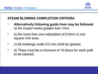

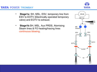

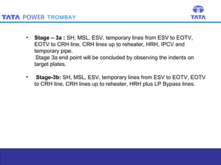
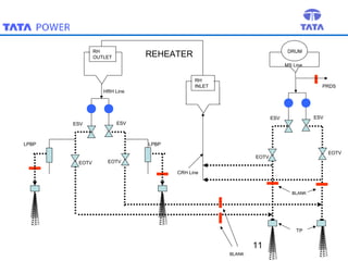

Steam blowing is carried out to remove debris from superheaters and reheaters that accumulate during manufacturing and installation. The objective is to prevent damage to turbine blades and valves. Steam blowing is considered complete when target plates show less than 5 indentations in the central zone or meet alternative criteria of indentation sizes. The procedure uses puffing and continuous blowing methods applying thermal shock to dislodge scale, which is removed by expanding steam. Various stages are outlined blowing different sections of piping and components. Completion is determined by observing target plate indentations.


![Edta cleaning procedurefor_150mw[1]](https://cdn.slidesharecdn.com/ss_thumbnails/edtacleaningprocedurefor150mw1-140108222158-phpapp02-thumbnail.jpg?width=640&height=640&fit=bounds)


