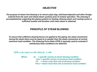
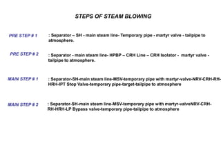
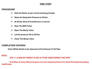
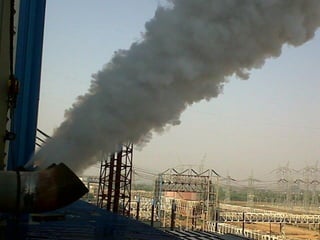
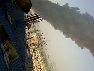
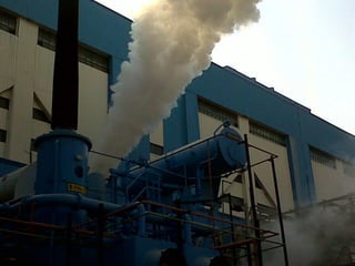
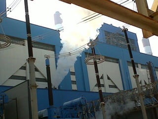
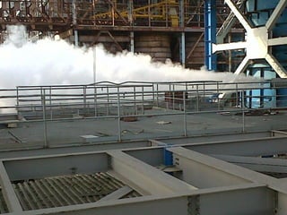
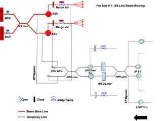
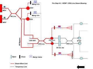
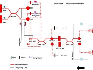
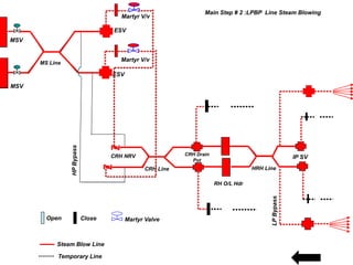
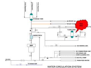
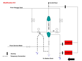
 OBJECTIVE AND PRINCIPLE OF STEAM BLOWING
 STEPS INVOLVED IN STEAM BLOWING ( WITH PATH DIAGRAM)
 PROCEDURE OF PRE-STEP STEAM BLOWING
 PROCEDURE OF MAIN STEP STEAM BLOWING
 COMPLETION CRITERIAN OF STEAM BLOWING
 PHOTOS OF SIPAT U # 1 STEAM BLOWING
STEAM BOWING PROCEDURE OF STAGE # 1
OBJECTIVE
The purpose of steam line blowing is to remove pipe slag, weld bead deposits and other foreign
material from the main and reheat steam systems prior to turbine operation. The cleaning is
accomplished by subjecting the piping systems to heating, blowing steam and cooling cycles in
sufficient number and duration until clean steam is obtained.
PRINCIPLE OF STEAM BLOWING
To ensure that sufficient cleaning forces are applied to the piping, the steam momentum
during the steam blow must be equal to or greater than the steam momentum at normal
maximum load condition. The Cleaning Force Ratio (CFR) is typically used to evaluate if
satisfactory blow conditions are obtained.
CFR = ( vb / vmcr ) x ( Fb / Fmcr )2 > 1.00
Where vb = specific volume at steam blowing condition
vmcr = specific volume at maximum load condition
Fb = steam mass flow rate at blowing condition
Fmcr = steam mass flow rate at maximum load condition
STEPS OF STEAM BLOWING
PRE STEP # 1 : Separator – SH - main steam line- Temporary pipe - martyr valve - tailpipe to
atmosphere.
PRE STEP # 2 : Separator - main steam line- HPBP – CRH Line – CRH Isolator - martyr valve -
tailpipe to atmosphere.
MAIN STEP # 1
: Separator-SH-main steam line-MSV-temporary pipe with martyr-valveNRV-CRH-
RH-HRH-LP Bypass valve-temporary pipe-tailpipe to atmosphere
MAIN STEP # 2
: Separator-SH-main steam line-MSV-temporary pipe with martyr-valve-NRV-CRH-RH-
HRH-IPT Stop Valve-temporary pipe-target-tailpipe to atmosphere
PRE STEP
PROCEDURE
 Start the Boiler as per normal working principle
 Raise the Seaprator Pressure to 40 Ksc
 At 40 Ksc Shut all Fuel Burners in service
 Stop The BRP Pump
 Open The Martyr Valve
 Let the pressure fall to 20 Ksc
 Close The Martyr Valve
COMPLETION CRITERIA
Clean White Smoke to be observed at the Exhaust of Tail Pipe
NOTE :
CFR < 1.0 AND NO TARGET PLATE IS TO BE USED DURING THIS STEP
First Blow at every Step to be given at much reduced pressure to check the temporary piping
healthiness
MAIN STEP
PROCEDURE
 Start the Boiler as per normal working principle
 Raise the Seaprator Pressure to 80 Ksc ( SH O/L Temp : 370
o
C)
 At 80 Ksc Shut all Fuel Burners in service
 Stop The BRP Pump
 Open The Martyr Valve
 Let the pressure fall to 40 Ksc
 Close The Martyr Valve
 Maintain the Separator Storage Tank Level
 Light The Boiler For Next Blowing
NOTE :
CFR > 1.0 AND NO TARGET PLATE IS TO BE USED DURING THIS STEP
First Blow at every Step to be given at much reduced pressure to check the temporary piping
healthiness
COMPLETION CRITERIAN
 No impacts with an diameter larger than 1 mm
 Not more than 4 impacts with an diameter larger than 0.5 mm
 Not more than 10 impacts with an diameter of 0.2 to 0.5 mm
A Target Plate is used to access the impacts of particle during steam Blowing. Steam Blowing
will be declared when
Final
SH
Final
SH
ESV
ESV
Martyr V/v
Martyr V/v
HP
Bypass
CRH Line
CRH NRV CRH Drain
Pot
RH O/L Hdr
HRH Line
MSV
LP
Bypass
IP SV
Open Close Martyr Valve
Steam Blow Line
Temporary Line
Pre Step # 1 : MS Line Steam Blowing
Final
SH
Final
SH
ESV
ESV
Martyr V/v
Martyr V/v
HP
Bypass
MS Line
CRH NRV CRH Drain
Pot
RH O/L Hdr
HRH Line
MSV
MSV
LP
Bypass
IP SV
Open Close Martyr Valve
Steam Blow Line
Temporary Line
Pre Step # 1 : MS Line Steam Blowing
LPBP V/ v
Final
SH
Final
SH
ESV
ESV
Martyr V/v
Martyr V/v
HP
Bypass
MS Line
CRH Line
CRH NRV CRH Drain
Pot
RH O/L Hdr
HRH Line
MSV
MSV
LP
Bypass
IP SV
Open Close Martyr Valve
Steam Blow Line
Temporary Line
Pre Step # 2 : HPBP / CRH Line Steam Blowing
Final
SH
Final
SH
ESV
ESV
Martyr V/v
Martyr V/v
HP
Bypass
MS Line
CRH Line
CRH NRV CRH Drain
Pot
RH O/L Hdr
HRH Line
MSV
MSV
LP
Bypass
IP SV
Open Close Martyr Valve
Steam Blow Line
Temporary Line
Main Step # 1 : HRH Line Steam Blowing
Final
SH
Final
SH
ESV
ESV
Martyr V/v
Martyr V/v
HP
Bypass
MS Line
CRH Line
CRH NRV CRH Drain
Pot
RH O/L Hdr
HRH Line
MSV
MSV
LP
Bypass
IP SV
Open Close Martyr Valve
Steam Blow Line
Temporary Line
Main Step # 2 :LPBP Line Steam Blowing
BRP
TO DRAIN HDR
FROM FEED WATER
BLR FILL PUMP
CHEM CLEANING SYS
CRH DRAIN LINE
SH COMMN DRAIN LINE
SH D.S.H. No1
ECO MIXING LINK
STORAGE TANK
MIXING PIECE
FLASH TANK
WR
ZR
WATER CIRCULATION SYSTEM
Sample Cooler
Blow Down Tan
Click
Here
TO ECO
To
Separator
From
Separator
From
Separator
FLASH
TANK
WR
ZR
From Storage Tank
Condensor
From Service Water
To Station Drain
Condensor
To D/A Floor
Modification # 1
Modification # 2
Dummy
Temporary Connection

steam_blowing.pdf

  • 1.
     OBJECTIVE ANDPRINCIPLE OF STEAM BLOWING  STEPS INVOLVED IN STEAM BLOWING ( WITH PATH DIAGRAM)  PROCEDURE OF PRE-STEP STEAM BLOWING  PROCEDURE OF MAIN STEP STEAM BLOWING  COMPLETION CRITERIAN OF STEAM BLOWING  PHOTOS OF SIPAT U # 1 STEAM BLOWING STEAM BOWING PROCEDURE OF STAGE # 1
  • 2.
    OBJECTIVE The purpose ofsteam line blowing is to remove pipe slag, weld bead deposits and other foreign material from the main and reheat steam systems prior to turbine operation. The cleaning is accomplished by subjecting the piping systems to heating, blowing steam and cooling cycles in sufficient number and duration until clean steam is obtained. PRINCIPLE OF STEAM BLOWING To ensure that sufficient cleaning forces are applied to the piping, the steam momentum during the steam blow must be equal to or greater than the steam momentum at normal maximum load condition. The Cleaning Force Ratio (CFR) is typically used to evaluate if satisfactory blow conditions are obtained. CFR = ( vb / vmcr ) x ( Fb / Fmcr )2 > 1.00 Where vb = specific volume at steam blowing condition vmcr = specific volume at maximum load condition Fb = steam mass flow rate at blowing condition Fmcr = steam mass flow rate at maximum load condition
  • 3.
    STEPS OF STEAMBLOWING PRE STEP # 1 : Separator – SH - main steam line- Temporary pipe - martyr valve - tailpipe to atmosphere. PRE STEP # 2 : Separator - main steam line- HPBP – CRH Line – CRH Isolator - martyr valve - tailpipe to atmosphere. MAIN STEP # 1 : Separator-SH-main steam line-MSV-temporary pipe with martyr-valveNRV-CRH- RH-HRH-LP Bypass valve-temporary pipe-tailpipe to atmosphere MAIN STEP # 2 : Separator-SH-main steam line-MSV-temporary pipe with martyr-valve-NRV-CRH-RH- HRH-IPT Stop Valve-temporary pipe-target-tailpipe to atmosphere
  • 4.
    PRE STEP PROCEDURE  Startthe Boiler as per normal working principle  Raise the Seaprator Pressure to 40 Ksc  At 40 Ksc Shut all Fuel Burners in service  Stop The BRP Pump  Open The Martyr Valve  Let the pressure fall to 20 Ksc  Close The Martyr Valve COMPLETION CRITERIA Clean White Smoke to be observed at the Exhaust of Tail Pipe NOTE : CFR < 1.0 AND NO TARGET PLATE IS TO BE USED DURING THIS STEP First Blow at every Step to be given at much reduced pressure to check the temporary piping healthiness
  • 5.
    MAIN STEP PROCEDURE  Startthe Boiler as per normal working principle  Raise the Seaprator Pressure to 80 Ksc ( SH O/L Temp : 370 o C)  At 80 Ksc Shut all Fuel Burners in service  Stop The BRP Pump  Open The Martyr Valve  Let the pressure fall to 40 Ksc  Close The Martyr Valve  Maintain the Separator Storage Tank Level  Light The Boiler For Next Blowing NOTE : CFR > 1.0 AND NO TARGET PLATE IS TO BE USED DURING THIS STEP First Blow at every Step to be given at much reduced pressure to check the temporary piping healthiness
  • 6.
    COMPLETION CRITERIAN  Noimpacts with an diameter larger than 1 mm  Not more than 4 impacts with an diameter larger than 0.5 mm  Not more than 10 impacts with an diameter of 0.2 to 0.5 mm A Target Plate is used to access the impacts of particle during steam Blowing. Steam Blowing will be declared when
  • 13.
    Final SH Final SH ESV ESV Martyr V/v Martyr V/v HP Bypass CRHLine CRH NRV CRH Drain Pot RH O/L Hdr HRH Line MSV LP Bypass IP SV Open Close Martyr Valve Steam Blow Line Temporary Line Pre Step # 1 : MS Line Steam Blowing Final SH Final SH ESV ESV Martyr V/v Martyr V/v HP Bypass MS Line CRH NRV CRH Drain Pot RH O/L Hdr HRH Line MSV MSV LP Bypass IP SV Open Close Martyr Valve Steam Blow Line Temporary Line Pre Step # 1 : MS Line Steam Blowing LPBP V/ v
  • 14.
    Final SH Final SH ESV ESV Martyr V/v Martyr V/v HP Bypass MSLine CRH Line CRH NRV CRH Drain Pot RH O/L Hdr HRH Line MSV MSV LP Bypass IP SV Open Close Martyr Valve Steam Blow Line Temporary Line Pre Step # 2 : HPBP / CRH Line Steam Blowing
  • 15.
    Final SH Final SH ESV ESV Martyr V/v Martyr V/v HP Bypass MSLine CRH Line CRH NRV CRH Drain Pot RH O/L Hdr HRH Line MSV MSV LP Bypass IP SV Open Close Martyr Valve Steam Blow Line Temporary Line Main Step # 1 : HRH Line Steam Blowing
  • 16.
    Final SH Final SH ESV ESV Martyr V/v Martyr V/v HP Bypass MSLine CRH Line CRH NRV CRH Drain Pot RH O/L Hdr HRH Line MSV MSV LP Bypass IP SV Open Close Martyr Valve Steam Blow Line Temporary Line Main Step # 2 :LPBP Line Steam Blowing
  • 17.
    BRP TO DRAIN HDR FROMFEED WATER BLR FILL PUMP CHEM CLEANING SYS CRH DRAIN LINE SH COMMN DRAIN LINE SH D.S.H. No1 ECO MIXING LINK STORAGE TANK MIXING PIECE FLASH TANK WR ZR WATER CIRCULATION SYSTEM Sample Cooler Blow Down Tan Click Here TO ECO To Separator From Separator From Separator
  • 18.
    FLASH TANK WR ZR From Storage Tank Condensor FromService Water To Station Drain Condensor To D/A Floor Modification # 1 Modification # 2 Dummy Temporary Connection