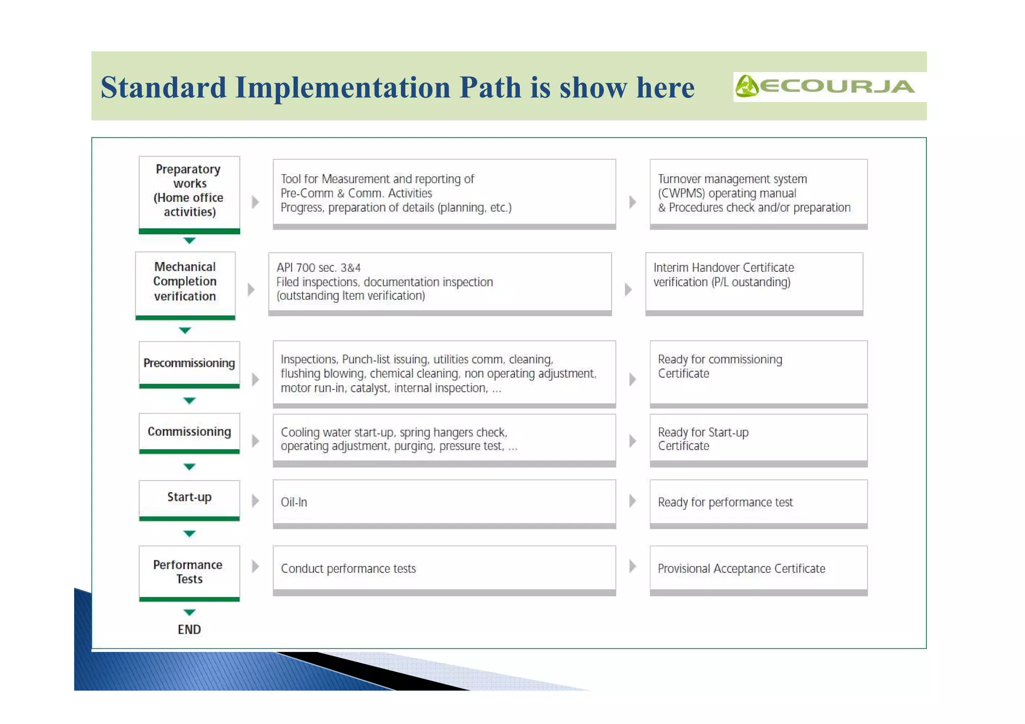
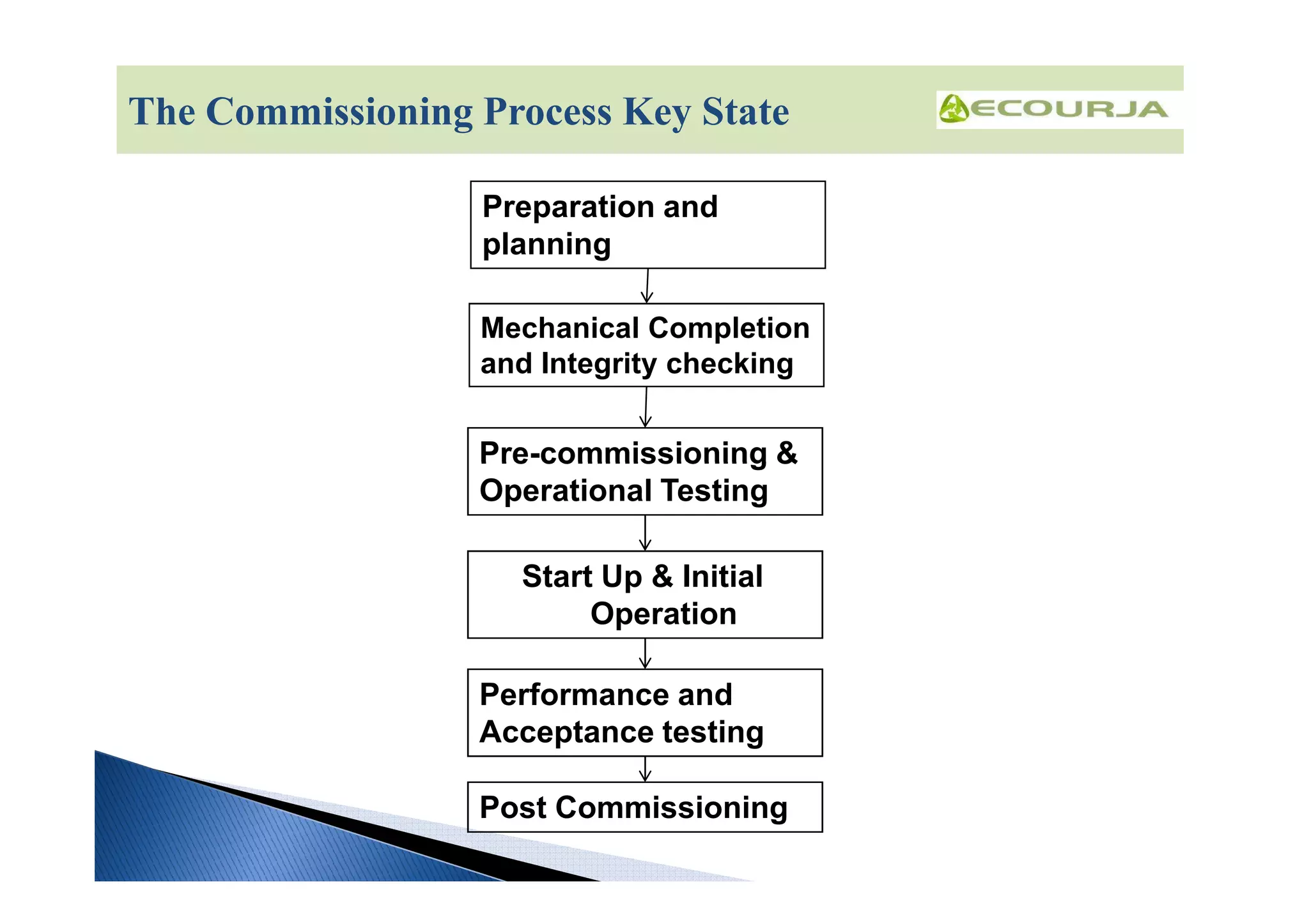
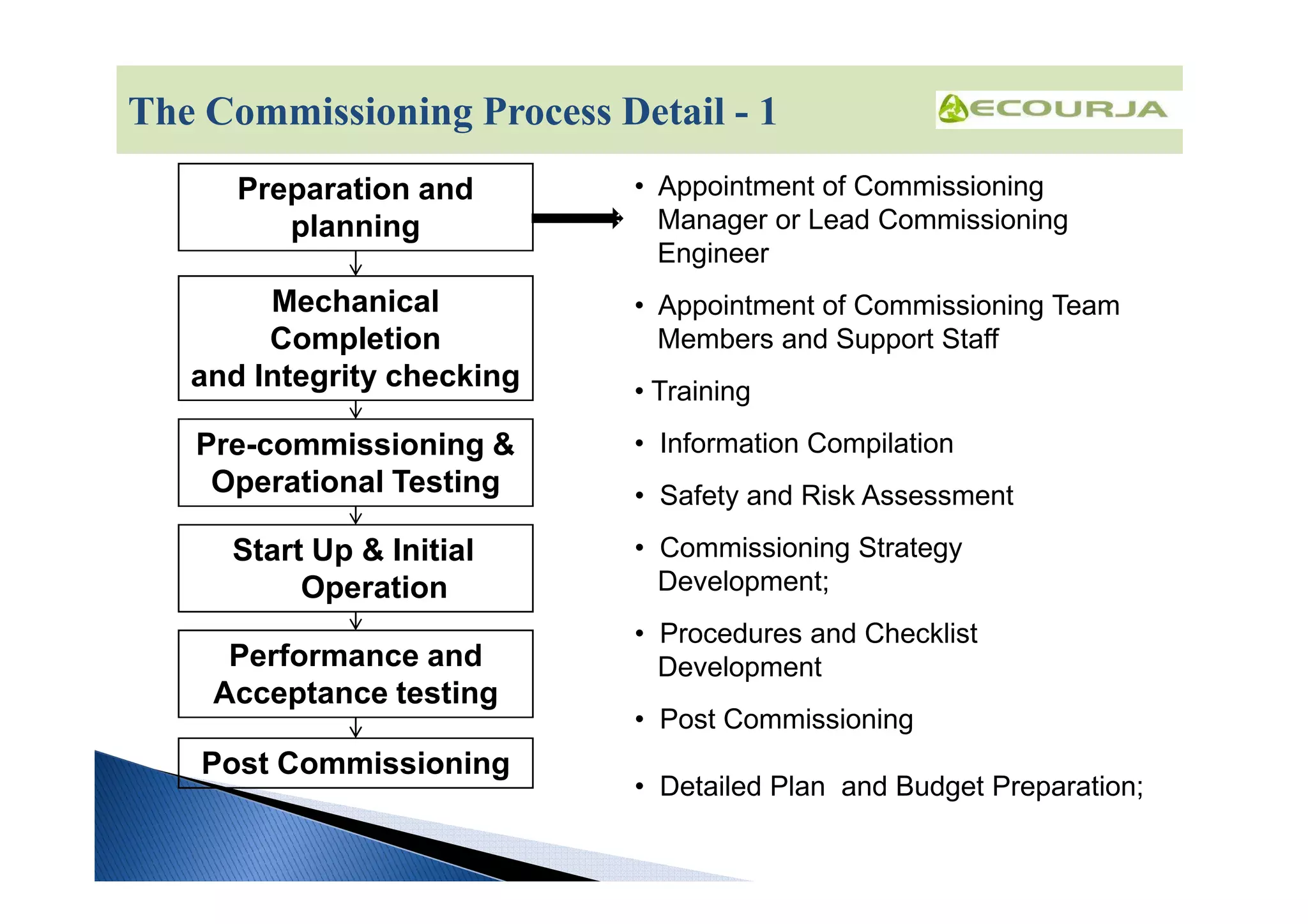
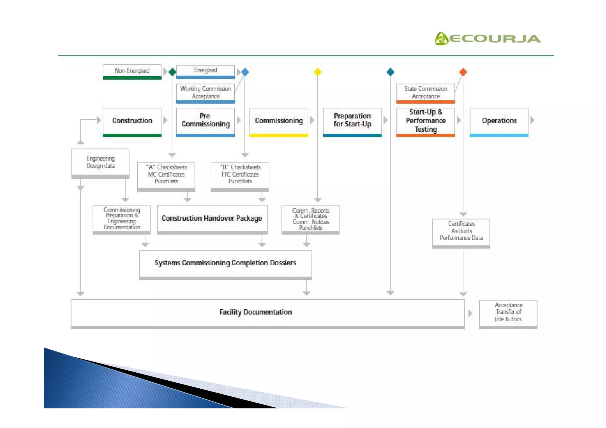
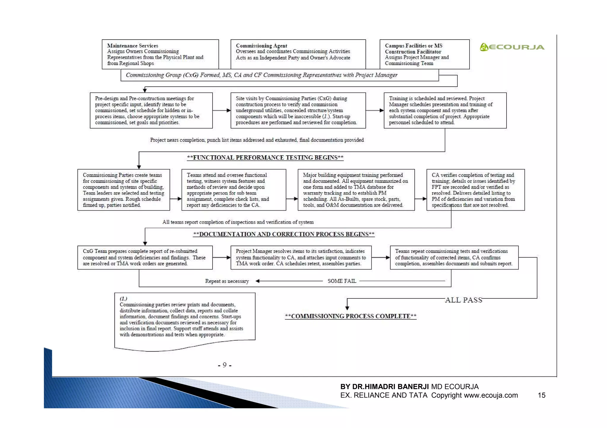
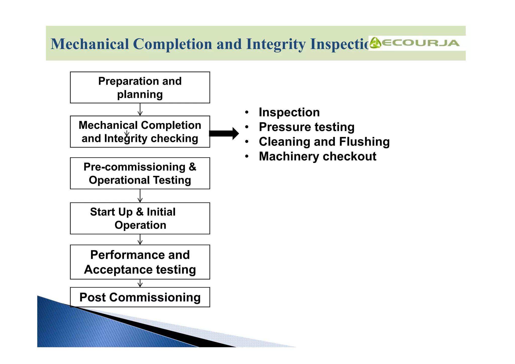
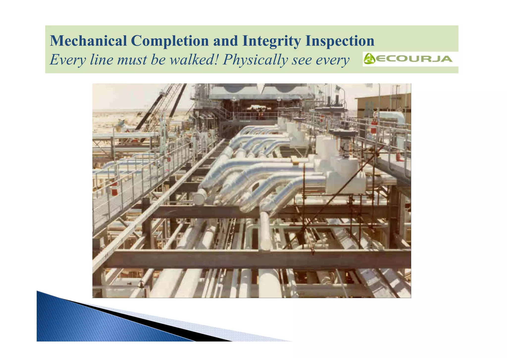
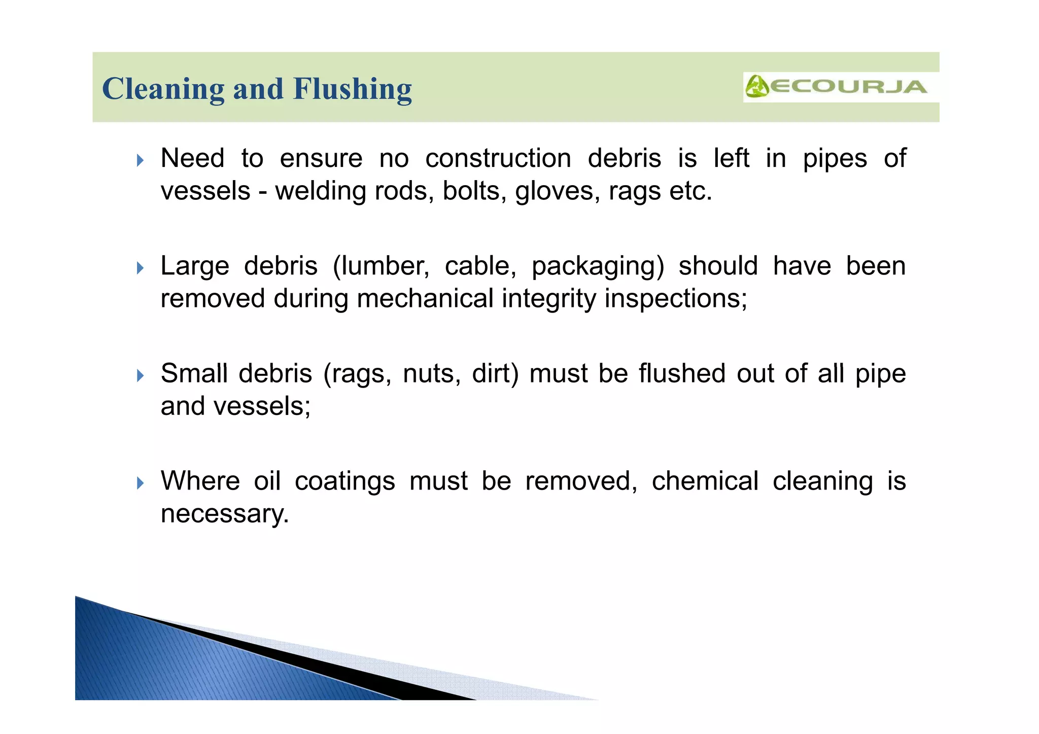
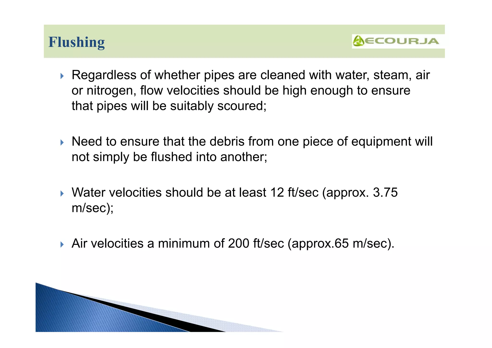
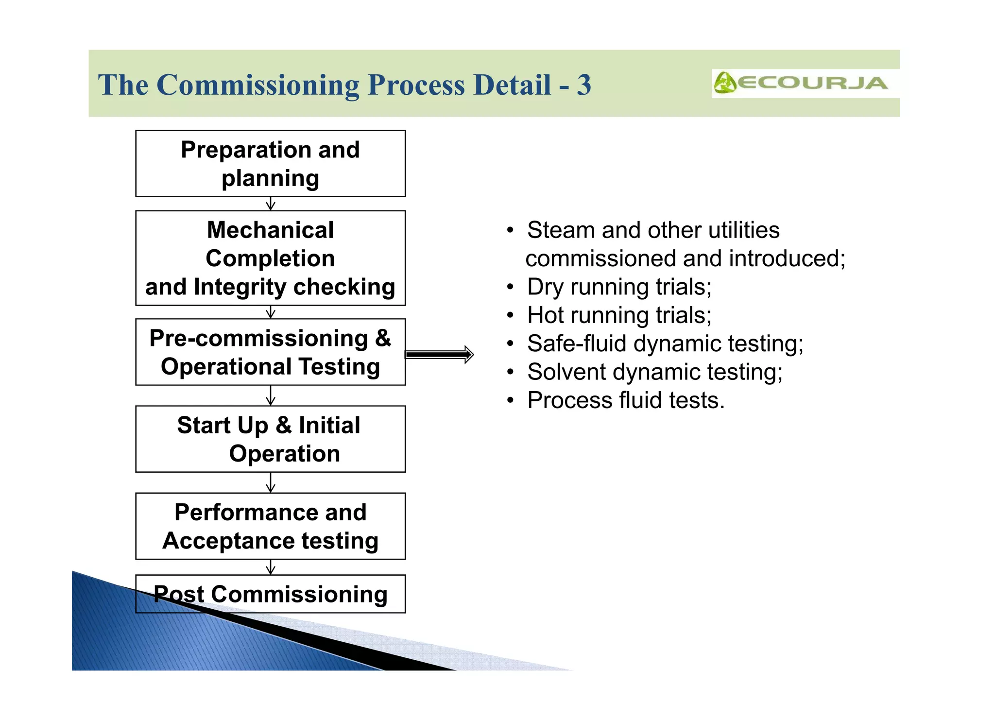
The document provides an overview of plant commissioning and start-up procedures. It discusses the commissioning process which includes preparation and planning, mechanical completion and integrity checking, pre-commissioning and operational testing, start-up and initial operation, performance and acceptance testing, and post-commissioning. It then goes into more detail on specific aspects of the commissioning process such as developing start-up procedures, commissioning utilities, pressure testing, cleaning and flushing, and pre-commissioning operational testing.
This program addresses in an integrated manner the key activities involved in the safe, effective and timely commissioning and start-up of a new plant or facility. Start Up and Commissioning of new plant and equipment presents both a major technical and management challenge. An organisation’s personnel must familiarise themselves with new equipment, processes and technologies, develop the relevant operating and safety procedures.
At the same time there is the requirement to execute an exceptionally large scope of work – much of it complex when compared to routine operations - over a short period of time, with equipment and plant which is as yet unproven and that may pose significant risks to personnel, environment and profitability.
This 5 day training course addresses the technical issues of commissioning and starting up various equipment and asset types commonly found in processing plant environments, the development of specific commissioning procedures, process and facility wide commissioning strategies. The course will also address the broader managerial issues of commissioning and start up planning, resourcing, budgeting and cost control, risk management – safety, environmental, financial and operational, problem solving and trouble shooting.
Pressure Relief Systems
BACKGROUND TO RELIEF SYSTEM DESIGN Vol.1 of 6
The Guide has been written to advise those involved in the design and engineering of pressure relief systems. It takes the user from the initial identification of potential causes of overpressure or under pressure through the process design of relief systems to the detailed mechanical design. "Hazard Studies" and quantitative hazards analysis are not described; these are seen as complementary activities. Typical users of the Guide will use some Parts in detail and others in overview.
Ammonia Plant Technology
Pre-Commissioning Best Practices
Piping and Vessels Flushing and Cleaning Procedure
CONTENTS
1 Scope
2 Aim/purpose
3 Responsibilities
4 Procedure
4.1 Main cleaning methods
4.1.1 Mechanical cleaning
4.1.2 Cleaning with air
4.1.3 Cleaning with steam (for steam networks only)
4.1.4 Cleaning with water
4.2 Choice of the cleaning method
4.3 Cleaning preparation
4.4 Protection of the devices included in the network
4.5 Protection of devices in the vicinity of the network
4.6 Water flushing procedure
4.6.1 Specific problems of water flushing
4.6.2 Preparation for water flushing
4.6.3 Performing a water flush
4.6.4 Cleanliness criteria
4.7 Air blowing procedure
4.7.1 Specific problems of air blowing
4.7.2 Preparation for air blowing
4.7.3 Performing air blowing
4.7.4 Cleanliness checks
4.8 Steam blowing procedure
4.8.1 Specific problems of steam blowing
4.8.2 Preparation for steam blowing
4.8.3 Performing steam blowing
4.8.4 Cleanliness checks
4.9 Chemical cleaning procedure
4.9.1 Specific problems of cleaning with a chemical solution
4.9.2 Preparation for chemical cleaning
4.9.3 Performing a chemical cleaning
4.9.4 Cleanliness criteria
4.10 Re-assembly - general guideline
4.11 Preservation of flushed piping
PetroSync - Pre-Commissioning, Commissioning and Start-UpPetroSync
Successful commissioning new or starting-up revised equipment and systems requires meticulous planning, organizing and controlling. Careful methodical, detailed planning – early – is the key to the success of any commissioning.
Implementation and application of a Process Safety Management System. This presentation will focus on the history, purpose and scope of a Process Safety Management (PSM) system. Topics covered include:
-Distinctions between personnel and process safety
-Framework and elements of PSM
-Importance of Safety Culture in the implementation and application of a PSM system
-Relevance and importance of regular audits and assessments of PSM systems
Pressure Safety Valve Sizing - API 520/521/526Vijay Sarathy
No chemical process facility is immune to the risk of overpressure to avoid dictating the necessity for overpressure protection. For every situation that demands safe containment of process gas, it becomes an obligation for engineers to equally provide pressure relieving and flaring provisions wherever necessary. The levels of protection are hierarchical, starting with designing an inherently safe process to avoid overpressure followed by providing alarms for operators to intervene and Emergency Shutdown provisions through ESD and SIL rated instrumentation. Beyond these design and instrument based protection measures, the philosophy of containment and abatement steps such as pressure relieving devices, flares, physical dikes and Emergency Response Services is employed
Improper management of highly hazardous chemicals, including toxic, reactive or flammable liquids, can cause accidental releases and emergency responses. OSHA’s Process Safety Management of Highly Hazardous Chemicals standard (29 CFR 1910.119) regulates the management of highly hazardous chemicals. Violations can carry fines of up to $126,000. Do you have a PSM program in place?
Process Safety Management (PSM) is a concern in any of the industries who store, handle and process hazardous chemicals & gases. The risks related to process safety are often managed in an isolated way.
This presentation will help organisations to manage process safety risks in a more structured fashion.
Line Sizing presentation on Types and governing Equations.Hassan ElBanhawi
Based on my 8 years of experience in Oil & Gas industry I can claim that you can find here All what you need to know about Pipeline Sizing. This is an introduction to understand more about their:-
-The basic idea.
-Simplified method for calculations.
-Equations.
-Data Tables.
-Worked Examples.
-Excel Sheets for Calculation.
-Links to other topics which may be interesting.
You can find also more at:
http://hassanelbanhawi.com/staticequipment/linesizing/
All the data and the illustrative figures presented here can be found through two reference books:-
ENGINEERING DATA BOOK by Gas Processors Suppliers Association
Process Technology - Equipment and Systems by Charles E. Thomas
Thank you.
Chemistry power point presentation on Hydrocarbons, which covers all the basic topics and sub- topics. Including Alkane,alkene and alkyne. This power point also consists of preparation of hydrcarbons.
This a 90 page power point.
GooD LucK !!!
Tender Process | A Complete Procurement GuideTender Process
All about Tenders and its Process | Here you will get all the information regarding tenders (Procurement) like what is tender, what is its process, types of tender, how to search tenders, what to do and what not to do in tendering, how to search tenders and more.... you can check our website for more details which is : http://tenderprocess.weebly.com/
E&I QC INSPECTOR RESUM AND documents.pdfIrfan786pak
I have good working experience more then 17 years in Oil and Gas ,Fertilizer, Chemical, Petrochemical, in Saudi Arabia & Pakistan , Having a good Experience in Maintenance, Pre Commissioning ,& Commissioning, Start-up and erection Activities, Good knowledge & working skills in plant Control Automation and different control systems such as DCS & ESD systems, Burner Management System, Condition Monitoring System, Turbine & Compressor Integrated Control Systems, F&G System, Production Wellheads, Water & Gas Injection Wellheads Hydraulic Control Panels etc. Ability to work alone as a shifter and fault finding & rectify. i am a Safety conscious & sound knowledge about work permits like cold, hot and entry work permits.in Maintenance and Commissioning 4 LTE2.48 % C4G + During my job I'm Responsible for the PM , CM & breakdown maintenance of various field Instrumentation like flow , pressure , temperature level transmitters , vibration probes , control / on - off valves which installed on Process piping , Skids . Self motivated Maintenance Professional with a demonstrated history of working in the Oil & Gas and Petrochemicals industry in instrument & Control system department securing16 years of Practical experience I am expertly capable in fault diagnosis , troubleshooting and process controls systems in process plant to ensure safety guidelines . I am experienced in modern process control instrumentation in chemicals , petrochemical , fertilizer , oil & gas and cryogenic plants in field of instrumentation . Highly skilled in electrical operations & maintenance . Has working proficiency in SAP system utilization and MS office My skills include but are not limited to : PLC , DCS & Vibration Monitoring System | Control Valve Operation & Maintenance | Loop Checking & SAT / FAT Activities | P & ID & Instruments Calibration | Transducers , SIS / SIL Concept , Positioners | Single Loop Controllers , I / P , ESD System | Turbine & Compressor Control Systems | Workshop / Field Test Equipment | Control Valves , Online Gas Analyzers | Burner Management System | Custody Transfer Metering | Commissioning Activities | Interpersonal Skills | Presentation Skills
I am available on
Email: irfanpak181@gmail.com
Mobile 📱: 00966533012366
ICH guidelines for validation Of Equipments by Nikita Sahu[1].pptxNikitaSahu39
VALIDATION- As per WHO,
Validation means providing documented evidence that any procedure, process, activity or system actually leads to the expected results.
As per FDA , Validation is establishing documented evidence, which provides a high degree of assurance that a specific process will produce a product meeting its pre determined specification & quality attributes.
Workshop on Plant Commissioning and Seamless Startup final.pdfHIMADRI BANERJI
Mr. Himadri Banerji a graduate of the prestigious
Indian Institute of Technology has over 35 years of
industry experience in Steel, Process and Thermal
Power Plants in India and Europe. After a stretch of 22
years in Tata Steel continued his career with such
illustrious companies as Rolls Royce, Torrent and
Reliance. His expertise includes planning, building,
testing, and start up and commissioning, besides
operating and maintaining Large Process Plants, Steel
Plants, Petrochemicals, Dyes and Paints, Cryogenic
Gases, Steam and Electric Power.
Mr. Banerji brings a diverse range of experience in
successful commissioning, having personally led start
up and commissioning teams for plants consisting of
large High Speed Rotary Equipment like Axial and
Radial Compressors, Steam and Gas Turbines, Water
Pumps, Temporary Power Solutions with Medium and
Large Diesel and Gas Engines, Static Systems like
Chemical Reactors, Air Separation Units, Process
Instrumentation and Control, CFBC, AFBC and PF
Steam Generators. His work also encompasses other
Plants like Water Treatment, Effluent Treatment
Plants, Reverse Osmosis and De-mineralising and Desalination
Plants.
He has also recently designed and implemented
chemical regimes for Control of Steam and Water
Cycle Chemistry during Start-up of Super-critical
Power Plants based on Union of the Electricity
Industry – EURELECTRIC guidelines an association of
the Electricity Industry within the European Union.
Dr Banerji regularly chairs and speaks at international
conferences and workshops on Procedures and
Systems for Managing Risk during Start-up and
Commissioning of plants. He has lectured widely in
various countries like Singapore, Malaysia, Indonesia, India
Brochure on Two Day Workshop on Plant Commissioning and Seamless Start Up By ...HIMADRI BANERJI
Overview of the wokshop:
To gain practical insights into:
Redefining the responsibilities of various departments to ensure a flawless start-up.
Ensuring that safety measures are put in place to
ensure zero LTIs during commissioning and startup.
Benchmarking your commissioning practices
against previous commissioning and start-up experiences.
Acquiring risk management techniques for better
prediction of what can go wrong during the commissioning and start-up process and identify
and plan effective mitigation measures.
Accelerating the ROI of your plant through proper
planning and management of resources during the
commissioning process.
Capturing the essence of commissioning and startup
in Greenfield and Brownfield Scenarios.
Gas Turbines Failures Applications & Root Cause Analysis.pptxHIMADRI BANERJI
SUBJECT PRESENTED AS CLASS ROOM LECTURES FOR ASSTT ENGINEERS OF ELECTRIOCITY GENERATION COMPANY OF BANGLADESH
2014-2017
HIMADRI BANERJI
INTERNATIONAL EXPERT GAS TURBINES
The aims of the O&M of Gas Turbines Workshop is to share the experiences of our internationally renowned expert with an aim to prevent such incidents and also to examine the factors and opportunities to increase plant safety, environmental performance. And improve uptime and availability all factors contributing to higher profitability.
The workshop will also examine scheduled maintenance and turnarounds which are opportunities to increase plant safety and environmental performance. By enhancing the mechanical integrity of HPI facilities, operating companies can achieve and maintain higher uptime and equipment availability; all are factors that contribute to higher profitability. Best-of-class companies hold the mindset that reliability programs provide great benefits. Investing in new monitoring and conditioning systems, along with preventive maintenance and inspection programs, can optimize unit and total facility performance.
The development of dry low NOx (DLN) combustors for gas turbines has cut the industry's consumption of water, while dramatically slashing air emissions. Unfortunately, this environmental enhancement has created an engineering challenge: The lean-burning DLN combustors are prone to flame instability, which can cause pressure pulsations large enough to destroy the combustor, launching debris downstream where it annihilates other hot-gas-path components. To detect and correct flame instability before it causes millions of dollars of turbine damage, savvy users have begun to install advanced sensors and robust software that monitor the combustor dynamics in real time.
High dynamics can limit hardware life and/or system operability. Thus, there have been various attempts to control combustion dynamics, to prevent degradation of system performance. There are two basic methods for controlling combustion dynamics in an industrial gas turbine combustion system: passive control and active control. As the name suggests, passive control refers to a system that incorporates certain design features and characteristics to reduce dynamic pressure oscillations. Active control, on the other hand, incorporates a sensor to detect, e.g., pressure fluctuations and to provide a feedback signal.
Which, When suitably processed by a controller, provides an input signal to a control device. The control device in turn operates to reduce the dynamic pressure oscillations. The workshop will examine the factors and the issues associated with combustor dynamics, and technologies like AMFM/CFM.
Benefits ofAttending
• LEARN best and effective practices in operations and maintenance of Gas Turbine Based Power Plants
• LEARN how to write and use SOPs
• IMPROVE your plants’ energy efficiency and availability
• ACHIEVE productive and safe operation
• NETWORK with other power plant professionals
• RECEIVE practical information for your CAPEX and OPEX expenditure budget planning
• LEARN about strategic procurement of High Value Spares and insurance
Making Artificial Intelligence Work in Managing ChangeHIMADRI BANERJI
“Making Artificial Intelligence (AI) Work In Managing Change ” is a Capability Improvement webinar which has been stitched together by a two member team comprising of a Senior CEO level Oil Gas and Energy Sector business executive who in his professional career spanning over decades has led multiple projects in digital
transformation in decision support systems in top organizations in the country and abroad in the contexts of
competion and uncertainty and an a senior IT expert who has hands on experience in designing the
configurations of hardware and the associated software in Digital Transformations in various areas including
Data Analysis, Machine Learning, Deep Learning, Neural Networks for implementing state of the art Artificial
Intelligence Systems in the Silicon Valley.
Two Day Integrated Workshop on “AI and Machine Learning for
Business Transformation”
It is essential for the success of every organization to stay ahead of the rapidly changing market by having access to
reliable and trustworthy information. Across the AI world, AI challenges are being converted by innovators into
tomorrow's business opportunies.
Success in this environment will depend on the speed of analysis and decision making, addressing customer needs
upskilling workforces and geng the right person to work on the right opportunity.
This one-of-a-kind integrated AI workshop enables you to dive deep into new depths of understanding and insights
into how AI is transforming work in organizaons. This workshop will unlock the right Data-driven AI techniques
and opportunities for project implementation in your organization that will set your business apart.
The methodology and techniques which enable machines to mimic human behavior and nature
are known as artificial intelligence. Machine learning is a subset of AI which allows a machine to
automatically learn from past data without explicit programming.
Risk management in nuclear projects and strategy of small reactors [compatibi...HIMADRI BANERJI
This technical document on risk management as a tool for improving nuclear power
plant (NPP) operations is part of an ongoing project on management of NPP operations in a
competitive environment. The overall objective of this project is to assist the management of
operating organizations and NPPs in identifying and implementing appropriate measures to
remain competitive in a rapidly changing business environment.
Lng project risk and appraisal 2012 final 03092012HIMADRI BANERJI
LNG Terminal is the disruptive technology becoming the most popular solution for countries needing natural gas for their power, fertiliser and transport sectors. This presentation is to understand the Risk Management, Financing, and insurance issues connected with this industry
FSRU (Floating Storage and Regasification Unit) LNG Terminal is the disruptive technology becoming the most popular solution for countries needing natural gas for their power, fertiliser and transport sectors. This presentation is to understand the Risk Management, Financing, and insurance issues connected with this industry
Risk management during start up and commissioning of super critical once thro...HIMADRI BANERJI
The Allowable Water and Steam Chemistry Regimes for Supercritical Units have been identified along with maximum deviations during start up and commissioning. This presentation gives guidelines for contracting norms to avoid damages.It is for the EPC Contractors in charge of construction of these units to understand the risks associated and design organizational skills both in technical and commercial areas to avoid major delays and damages.
FSRU (Floating Storage and Regasification Unit) LNG Terminal is the disruptive technology becoming the most popular solution for countries needing natural gas for their power, fertiliser and transport sectors. This presentation is to understand the Risk Management, Financing, and insurance issues connected with this industry
Managing Smart Grids, Power System Networks with Analytics HIMADRI BANERJI
Big Data is playing a significant role in managing effectively the data analytics requirement from the infrastructure arising out of smart grid implementation n T&D Utilities..The presentation looks at some of the major issues and initiatives.
Liquefied Natural Gas project risk and appraisal HIMADRI BANERJI
Fundamentals of the LNG business value chain and project and risk appraisal. This includes understanding the dynamics of the international LNG market covering the pricing mechanisms, regional and global market drivers, and the behaviour of importing and exporting countries, LNG trade flows, Asian LNG market and indexation mechanisms, various kinds of contracting structure, detailed understanding of derivatives and arbitrage opportunities.
Challenges in building the 21st century energy infrastructureHIMADRI BANERJI
Major Challenges in Building the 21st Century Energy Infrastructure are discussed. The concepts of Risk Management is introduced with subtlety in its impact on meeting such challenges. A treatise on project management with risk mitigation for infrastructure projects, Presentation taken from lectures on Infrastructure Capital Management delivered to the class of 2010-11 at IIM Ahmedabad,
Thermal coal upgradation and conversion in india ibc asia, jakarta april 25, ...HIMADRI BANERJI
PRIORITIES ON ENERGY GENERATION SECTOR ARE:Increased use of Advanced Fossil Fuel Technology, Promote CCT where coal is main stay fuel for Power Generation AND Reduce Atmospheric Pollution from Energy Generating Systems WHILE Ensuring energy security . India's initiatives in using the low rank coals like lignite, or the high ash coals are dicussed.
Clean Coal Technology:Indian Perspective by Himadri Banerji HIMADRI BANERJI
The clean coal technology (CCT) market is likely to see substantial spending over the next decade as governments and industry alike invest in R&D, installation, and operation in this growing market. The emergence of clean coal technologies has created market opportunities for equipment manufacturers and utilities. Presented here is the Indian perspective from the talk given at TREC STEP program on invitation from E&Y at REC Tiruchirapalli on 25th Jan 2012
Start Up and Commissioning of Supercritical Power Stations: Risk Management P...HIMADRI BANERJI
Start Up protocols play a major part in risk management for modern Supercritical power plants especially during start-up and commissioning. EPC contractors must be alert to contract conditions set by owners and start up engineers on deviation of steam and water chemistry conditions especially.
Discover the innovative and creative projects that highlight my journey throu...dylandmeas
Discover the innovative and creative projects that highlight my journey through Full Sail University. Below, you’ll find a collection of my work showcasing my skills and expertise in digital marketing, event planning, and media production.
Unveiling the Secrets How Does Generative AI Work.pdfSam H
At its core, generative artificial intelligence relies on the concept of generative models, which serve as engines that churn out entirely new data resembling their training data. It is like a sculptor who has studied so many forms found in nature and then uses this knowledge to create sculptures from his imagination that have never been seen before anywhere else. If taken to cyberspace, gans work almost the same way.
Enterprise Excellence is Inclusive Excellence.pdfKaiNexus
Enterprise excellence and inclusive excellence are closely linked, and real-world challenges have shown that both are essential to the success of any organization. To achieve enterprise excellence, organizations must focus on improving their operations and processes while creating an inclusive environment that engages everyone. In this interactive session, the facilitator will highlight commonly established business practices and how they limit our ability to engage everyone every day. More importantly, though, participants will likely gain increased awareness of what we can do differently to maximize enterprise excellence through deliberate inclusion.
What is Enterprise Excellence?
Enterprise Excellence is a holistic approach that's aimed at achieving world-class performance across all aspects of the organization.
What might I learn?
A way to engage all in creating Inclusive Excellence. Lessons from the US military and their parallels to the story of Harry Potter. How belt systems and CI teams can destroy inclusive practices. How leadership language invites people to the party. There are three things leaders can do to engage everyone every day: maximizing psychological safety to create environments where folks learn, contribute, and challenge the status quo.
Who might benefit? Anyone and everyone leading folks from the shop floor to top floor.
Dr. William Harvey is a seasoned Operations Leader with extensive experience in chemical processing, manufacturing, and operations management. At Michelman, he currently oversees multiple sites, leading teams in strategic planning and coaching/practicing continuous improvement. William is set to start his eighth year of teaching at the University of Cincinnati where he teaches marketing, finance, and management. William holds various certifications in change management, quality, leadership, operational excellence, team building, and DiSC, among others.
What are the main advantages of using HR recruiter services.pdfHumanResourceDimensi1
HR recruiter services offer top talents to companies according to their specific needs. They handle all recruitment tasks from job posting to onboarding and help companies concentrate on their business growth. With their expertise and years of experience, they streamline the hiring process and save time and resources for the company.
The world of search engine optimization (SEO) is buzzing with discussions after Google confirmed that around 2,500 leaked internal documents related to its Search feature are indeed authentic. The revelation has sparked significant concerns within the SEO community. The leaked documents were initially reported by SEO experts Rand Fishkin and Mike King, igniting widespread analysis and discourse. For More Info:- https://news.arihantwebtech.com/search-disrupted-googles-leaked-documents-rock-the-seo-world/
RMD24 | Retail media: hoe zet je dit in als je geen AH of Unilever bent? Heid...BBPMedia1
Grote partijen zijn al een tijdje onderweg met retail media. Ondertussen worden in dit domein ook de kansen zichtbaar voor andere spelers in de markt. Maar met die kansen ontstaan ook vragen: Zelf retail media worden of erop adverteren? In welke fase van de funnel past het en hoe integreer je het in een mediaplan? Wat is nu precies het verschil met marketplaces en Programmatic ads? In dit half uur beslechten we de dilemma's en krijg je antwoorden op wanneer het voor jou tijd is om de volgende stap te zetten.
Improving profitability for small businessBen Wann
In this comprehensive presentation, we will explore strategies and practical tips for enhancing profitability in small businesses. Tailored to meet the unique challenges faced by small enterprises, this session covers various aspects that directly impact the bottom line. Attendees will learn how to optimize operational efficiency, manage expenses, and increase revenue through innovative marketing and customer engagement techniques.
Explore our most comprehensive guide on lookback analysis at SafePaaS, covering access governance and how it can transform modern ERP audits. Browse now!
Falcon stands out as a top-tier P2P Invoice Discounting platform in India, bridging esteemed blue-chip companies and eager investors. Our goal is to transform the investment landscape in India by establishing a comprehensive destination for borrowers and investors with diverse profiles and needs, all while minimizing risk. What sets Falcon apart is the elimination of intermediaries such as commercial banks and depository institutions, allowing investors to enjoy higher yields.
Accpac to QuickBooks Conversion Navigating the Transition with Online Account...PaulBryant58
This article provides a comprehensive guide on how to
effectively manage the convert Accpac to QuickBooks , with a particular focus on utilizing online accounting services to streamline the process.
Skye Residences | Extended Stay Residences Near Toronto Airportmarketingjdass
Experience unparalleled EXTENDED STAY and comfort at Skye Residences located just minutes from Toronto Airport. Discover sophisticated accommodations tailored for discerning travelers.
Website Link :
https://skyeresidences.com/
https://skyeresidences.com/about-us/
https://skyeresidences.com/gallery/
https://skyeresidences.com/rooms/
https://skyeresidences.com/near-by-attractions/
https://skyeresidences.com/commute/
https://skyeresidences.com/contact/
https://skyeresidences.com/queen-suite-with-sofa-bed/
https://skyeresidences.com/queen-suite-with-sofa-bed-and-balcony/
https://skyeresidences.com/queen-suite-with-sofa-bed-accessible/
https://skyeresidences.com/2-bedroom-deluxe-queen-suite-with-sofa-bed/
https://skyeresidences.com/2-bedroom-deluxe-king-queen-suite-with-sofa-bed/
https://skyeresidences.com/2-bedroom-deluxe-queen-suite-with-sofa-bed-accessible/
#Skye Residences Etobicoke, #Skye Residences Near Toronto Airport, #Skye Residences Toronto, #Skye Hotel Toronto, #Skye Hotel Near Toronto Airport, #Hotel Near Toronto Airport, #Near Toronto Airport Accommodation, #Suites Near Toronto Airport, #Etobicoke Suites Near Airport, #Hotel Near Toronto Pearson International Airport, #Toronto Airport Suite Rentals, #Pearson Airport Hotel Suites
3.0 Project 2_ Developing My Brand Identity Kit.pptxtanyjahb
A personal brand exploration presentation summarizes an individual's unique qualities and goals, covering strengths, values, passions, and target audience. It helps individuals understand what makes them stand out, their desired image, and how they aim to achieve it.
Buy Verified PayPal Account | Buy Google 5 Star Reviewsusawebmarket
Buy Verified PayPal Account
Looking to buy verified PayPal accounts? Discover 7 expert tips for safely purchasing a verified PayPal account in 2024. Ensure security and reliability for your transactions.
PayPal Services Features-
🟢 Email Access
🟢 Bank Added
🟢 Card Verified
🟢 Full SSN Provided
🟢 Phone Number Access
🟢 Driving License Copy
🟢 Fasted Delivery
Client Satisfaction is Our First priority. Our services is very appropriate to buy. We assume that the first-rate way to purchase our offerings is to order on the website. If you have any worry in our cooperation usually You can order us on Skype or Telegram.
24/7 Hours Reply/Please Contact
usawebmarketEmail: support@usawebmarket.com
Skype: usawebmarket
Telegram: @usawebmarket
WhatsApp: +1(218) 203-5951
USA WEB MARKET is the Best Verified PayPal, Payoneer, Cash App, Skrill, Neteller, Stripe Account and SEO, SMM Service provider.100%Satisfection granted.100% replacement Granted.
As a business owner in Delaware, staying on top of your tax obligations is paramount, especially with the annual deadline for Delaware Franchise Tax looming on March 1. One such obligation is the annual Delaware Franchise Tax, which serves as a crucial requirement for maintaining your company’s legal standing within the state. While the prospect of handling tax matters may seem daunting, rest assured that the process can be straightforward with the right guidance. In this comprehensive guide, we’ll walk you through the steps of filing your Delaware Franchise Tax and provide insights to help you navigate the process effectively.
3. The Commissioning Process Key State
Preparation and
planning
Mechanical Completion
and Integrity checking
Pre-commissioning &
Operational Testing
Start Up & Initial
Operation
Performance and
Acceptance testing
Post Commissioning
4. The Commissioning Process Detail - 1
Preparation and • Appointment of Commissioning
planning Manager or Lead Commissioning
Engineer
Mechanical • Appointment of Commissioning Team
Completion Members and Support Staff
and Integrity checking • Training
Pre-commissioning & • Information Compilation
Operational Testing • Safety and Risk Assessment
Start Up & Initial • Commissioning Strategy
Operation Development;
• Procedures and Checklist
Performance and Development
Acceptance testing
• Post Commissioning
Post Commissioning
• Detailed Plan and Budget Preparation;
5. The Commissioning Process Details – 1
Facility Commissioning Issues
Time phasing construction and commissioning activities
Time phasing the commissioning of the various parts of the plant relative
to each other
Relationships and timings determining when various systems need to be
available:
Electrical, Steam, Water, Instrumentation
Sequencing of the overall plant startup and shutdown to ensure we do
not create unsafe conditions
Initial start up
Process Control and Shutdown
Performance testing
6. Developing Startup Procedures
Engineering and construction companies generally follow a
systematic procedure where by their startup engineers
review the process design several times as it is developed
After the first review, a preliminary start-up and operations
procedure is written
Decide what must be added to the design to make the
process capable of being started up and operated;
By the time the final engineering flow-sheets have been
released a complete startup and operating instructions
manual should have been completed.
7. Issues Considered
Are various part of the process too depend on one another
Is there enough surge capacity
Are there provisions to prevent abnormal pressures, temperatures
and rates of reaction
Where are additional valves and bypass lines needed
Special lines to allow equipment to be started up
and rerun product/raw materials.
8. System Level Activities
Utilities systems - steam, instrument air, process water, fire
water, drainage, condensate return
Electrical systems
Instrumentation and instrumentation systems;
Cleaning and flushing
Purging
Initial start up and shutdowns
Performance testing
9. Equipment Level Activities
Pressure testing & mechanical integrity testing of vessel,
columns and pipe work.
Heat Echanger, condensers, coolers etc.
Mechanical equipment and machinery.
Control Systems and Instrumentation.
Operational testing.
Proof testing and acceptance.
10. What can be done before mechanical
completion
Utilities commissioning
Lube and Seal-Oil Systems Cleaned
Instrumentation and Control Loops Proven
Piping, Towers and Vessels Cleaned
Boil-Out, Dry-Out and Acid Cleaning
Turbine, Motor and Pump Run-Ins
Nitrogen Purge and Tightness Testing
11. Building Organisational Learning
Best Practice
Benchmarking Improvement
Industry Processes
Standards
Corporate Procedures and
Knowledge Base Check sheets
Legislation
Experience
Process Design Specific
Machinery
&Equipment
12.
13. Procedures
Procedures are written routines/instructions that describe the logical
sequence of activities required to perform a work process and the
specific actions required to perform each activity.
If there are no written procedures, there is no basis for
monitoring performance, focus for improvement or
mechanism by which to capture learning.
The establishment of procedures and routines allow more time and
mental energy to deal with the unexpected, which always happen
during commissioning.
14. Commissioning / Startup Logic
A Critical Path Network (Plan) with written procedures
with related documents are required. These should
define for the facility, each plant system:
• The order in which the systems will be started up.
• Individual activities at each stage.
• Operation testing requirements.
• Durations, waiting times, cooling times.
• Total duration for starting up each system.
• Resources required - labour, materials, equipment services
• Temperatures, pressures, fluid flows used.
16. Commissioning / Startup and Shutdown Issues
At the facility, system and equipment level, we want to avoid:
• Creation/existence of explosive mixtures, usually because of
the presence of air.
• Water hammer and water based explosion effects, due to
contact between water and hot substances (steam, oil, etc.)
In particular, during commissioning hot fluids and gases will be
coming into contact with cold surfaces in places that would be
hot under normal operations.
18. Mechanical Completion and Integrity Inspection
Preparation and
planning
• Inspection
Mechanical Completion • Pressure testing
and Integrity checking • Cleaning and Flushing
• Machinery checkout
Pre-commissioning &
Operational Testing
Start Up & Initial
Operation
Performance and
Acceptance testing
Post Commissioning
19. Categories of Process Equipment
Distillation Towers / Fractionation Towers
Re-boilers & Other Shell & Tube Heat Exchangers
Boilers and Fired Heaters
Pressure Vessels and Pipe-work
Fin-Fan Coolers
Condensers
Machinery/Rotating Equipment
Valves
Instrumentation
Electrical Equipment
20. Machinery / Rotating Equipment
Pumps
Steam Turbines
Gas Turbines
Compressors
Gas Engines
Electric Motors
21. Mechanical Completion and Integrity
Inspection
Involves checking that everything has been built and it there
as per specification. Refer:
• Piping Plan Drawings
• Layout and construction drawings
• P & ID’s
Electrical systems, Instrumentation and control systems
checkout done by appropriately qualified personnel
(Electricians and Instrumentation technicians).
General commissioning engineers generally do not get
involved in this in a hands-on manner.
22. Mechanical Completion and Integrity
Inspection Procedure
Divide plant into manageable areas;
In a large plant, assign individuals or teams to specific areas;
Establish a master set of piping plan drawings and P&ID’s,
mark up areas:
Individual commissioning engineers or teams walk every line
and mark up every item that can be confirmed as present on
master set of drawings.
Use different colored “highlighter” pens to indicate different
services.
24. Mechanical Completion and Integrity
Inspection Procedure Hints / Tips
Ensure pipes, vessels, valves etc. are all in the right place.
Valves are correct type - globe, gate, control;
Vents, drains, steam traps etc.
Flanges, bolts, types of bolts.
Blind flanges and swing able blinds in place,
correct rating.
Check all tag numbers.
Punch list any non-conformances.
25. Pipe Stressing
Piping should provide adequately for expansion and
contraction due to temperature changes, without placing
excessive stresses on equipment;
Misalignment between matching flanges on pipe work
particular where there are changes indirection (elbows) can
cause stressing;
Misalignments where pipe-work connects to machinery,
vessels and other process equipment;
Can often be seen visually, or checked with gauges using the
same procedures we use to align rotating equipment.
27. Piping and equipment support
Mobile supports permit and guide the thermal growth of
equipment undergoing temperature change;
If they do not function correctly, vessels, equipment, pipe work,
nozzles heat exchangers etc. may be damaged.
29. Piping and Equipment Supports
Inspection prior to start up:
• Check that installed according to specification and not
jammed;
Inspection during warm up:
• Check thermal growth is occurring and supports are
responding as per design;
• Check that there is no surface buckling or crimping - this
needs to be corrected;
• Check expansion joints;
• Check long straight runs of piping for bowing or support
shoe that may have slipped;
• Rule of thumb - bowing is excessive if you can see it.
30. Piping and Equipment Supports
Inspection after cool-down:
• Check that sliding supports have returned to original
positions;
• Establish that equipment can expand and contract as
required.
31. Inspection of Spring Supports
Before hydro-testing:
• Check that spring stops are installed. (If not, the weight of
water in pipe will deform the spring).
After hydro-testing but before heating:
• Check that stops are removed;
• Check that spring pointer is positioned to cold setting;
32. Inspection of Spring Supports
During and at end of heating:
• Check pointer has not exceeded hot setting;
After cool down:
• check to establish piping can expand and
• establish that springs can absorb loads.
34. Inspection of Vessels and Columns
The inspection of vessels, columns and reactors should be
scheduled to be completed before construction has closed
them up;
Other inspections - e.g. for completeness or piping, insulation,
safety etc. can be scheduled later;
If a vessel has been sealed up by construction, it is your duty to
inspect it, even it construction resist.
35. Inspection of Vessels and Columns
Check that distributors have been installed correctly;
De-misters installed correctly and of correct materials, design,
type;
Vortex breakers in place;
Trays - packed or “bubble-cap” are correct:
• Bubble caps not jammed or damaged, down comers clear,
supports all OK.
37. Pressure Testing - Objectives
The objective of pressure testing is to confirm the mechanical
integrity of the plant;
Verifying capability of containing the pressures it has been
designed to hold;
Ensure there are no leaks and verify that the plant can be
reliably made leak free;
Identify any vulnerabilities well before the plant is placed into
service;
Meet the requirements of legislation, local, international and
industry standards.
38. Pressure Testing – Responsibilities
Pressure tests of tanks, reactors and piping for mechanical
strength and tightness of joints is usually done by the
construction team;
Commissioning team representatives should witness and
certify the tests;
Need to verify that all necessary safety precautions have
been taken;
39. Pressure Testing - Procedures
Water for testing and flushing should contain a rust inhibitor -
one low in chloride content for stainless steel lines;
After testing, water should be drained completely from all
lines that do not normally carry water, steam or steam
condensate;
All low points should be checked for presence of water;
Lines should be dried by blowing hot air, dry inert gas or
instrument air.
40. Pressure Testing – Vacuum Systems
Final checks of vacuum systems are best performed by
pulling a vacuum and observing the rate of pressure rise in
the blocked in system;
Excessive leaks can then be located by applying a mild
positive pressure and testing each flange with bubble
solution.
41. Pressure Testing – Procedures 2
Isometric drawings of all systems to be tested should be
displayed on a board and marked up as each section is
tested;
Hydro testing of piping and equipment according to code
requirements to confirm mechanical strength should be
carried out on groups of equipment naturally suggested by
design pressure and function;
All water, steam, condensate, oil, gas and process steam
piping should be hydro tested;
Major equipment that has already been tested as part of
manufacturing may be isolated by blanks.
43. Cleaning and Flushing
Need to ensure no construction debris is left in pipes of
vessels - welding rods, bolts, gloves, rags etc.
Large debris (lumber, cable, packaging) should have been
removed during mechanical integrity inspections;
Small debris (rags, nuts, dirt) must be flushed out of all pipe
and vessels;
Where oil coatings must be removed, chemical cleaning is
necessary.
44. Cleaning and Flushing
Before flushing is started, check the process
thoroughly to ensure:
• Screens have been installed in front of pump suctions.
• Blinds in front of equipment such as compressors and
turbines;
• “Jumper” spool pieces to allow for continuity of flow.
45. Flushing
Can be handled by geographic plant area;
Sections too large for water flushing:
• Pipes greater than 30 in diameter (0.75 m), or
• Pipes that should not be touched with water;
Should all be blown out with air or inert gas.
46. Flushing
Regardless of whether pipes are cleaned with water, steam, air
or nitrogen, flow velocities should be high enough to ensure
that pipes will be suitably scoured;
Need to ensure that the debris from one piece of equipment will
not simply be flushed into another;
Water velocities should be at least 12 ft/sec (approx. 3.75
m/sec);
Air velocities a minimum of 200 ft/sec (approx.65 m/sec).
48. The Commissioning Process Detail - 3
Preparation and
planning
Mechanical • Steam and other utilities
Completion commissioned and introduced;
and Integrity checking • Dry running trials;
• Hot running trials;
Pre-commissioning & • Safe-fluid dynamic testing;
Operational Testing • Solvent dynamic testing;
• Process fluid tests.
Start Up & Initial
Operation
Performance and
Acceptance testing
Post Commissioning
50. Commissioning Utilities
Utilities commissioning usually represents the first phase of
commissioning, as these usually need to operational first,
before the rest of the plant can be commissioned;
The steps for commissioning each utility should be planned in
detail;
Provides planning practice for planning the startup of the
main plant.
51. Commissioning Utilities – Broad Guidelines
Check supply pressures of all services - steam, cooling water,
instrument air, nitrogen etc.
At the most distant points, open drains, vent valves or pipe
flanges and purge until fluids come out clean and rust free;
Purge/blow out lines to each piece of equipment;
Check that instrument air is clean and dry, and at correct
pressure;
Circulate water to waste water system until water lines clear
and clean;
Flush waste water and drain systems to ensure no blockages;
Check operation of steam traps;
Drain condensate to waste water until is clean.
52. Commissioning Utilities
Introducing Steam
Steam usually represents the first “hazardous” fluid
introduced into the “new” system;
Admit steam slowly into the distribution system with
atmospheric bleeds open:
• Cold pipes will condense steam in places where it would
not under normal operation;
• Can lead to “water hammer”- can distort and rupture lines;
After system has been warmed, slowly raise pressure and
blow down the system with traps bypassed, until clean;
Then place steam traps into service and check operation.
53. High Pressure Steam Systems
Specific Issues
The cleanliness and purity of high pressure steam systems -
particularly where the steam is used to drive a steam turbine
should be checked by use of a “target”;
For new boilers, or new sections added to steam system -
blow down at full pressure;
When steam appears clean, fit a target with a “mirrored”
surface (ie. Small steel plate which has been polished, so that
it is in the steam blow down stream;
Blow down the boiler or system so that the target is impinged
upon for a few minutes;
Check target - ensure there are no small “pock marks” left on
the target. If pock marked - repeat process.
55. Machinery and System Check-Out
Check-out
A crew of specialized individuals need to be mobilized to do the check-out
and pre-commissioning in a plant:
• All control loops, settings of PID loops, stroking of valves, transmitter
calibration, etc…
• P&ID conformity; is the plant built according the P&ID, is all instrumentation
correctly installed, are they connected, are all valves correctly installed, etc…
• Mechanical installation of all (major) equipment; levelling correct, alignments done,
oil flushing satisfactory, etc…
• Analyzer calibration, checking of tubing, problem assessment and
identification.
• Control systems functional check, communications check, integrity check, safety
features checking, emergency stops check, critical operating parameters checking,
etc…
• Electrical check-out; check-out of MCC’s, switchgears, selectivity studies,
protection systems, functional checks, etc…
56. Commissioning Electrical Systems
The following checks are typical of what is required
Open circuit breakers and switches;
Check that all bus-bars are free of dirt and foreign matter;
Check grounding systems for continuity and resistance. Make
sure all electrical equipment, vessels, structures are
connected to the grounding system in accordance with
drawings and specifications;
Check that all sealed fittings are filled with proper sealants, all
explosion proof, vapour-tight, dust-tight and weather tight
enclosures are properly closed and secured;
Check motor control and power circuitry for correct hookup.
57. Commissioning Electrical Systems – 2
The Following checks are typical of what is required
Check all nameplates and panel directories to ensure that each
circuit breaker and switch does control the proper circuit. Label all
switches even though their application may seem obvious;
Close main transformer primary disconnect switch and switch-gear
main circuit breaker;
Check voltmeter at switch-gear for proper voltage;
Close first switch-gear circuit breaker, second, third etc.
Close first motor control centre main circuit breaker, then
each motor starter circuit breaker. Repeat for each MCC.
Check overload breakers and heaters to ensure that the correct
capacity units have been installed.
58. Commissioning Electrical Systems – 3
The following checks are typical of what is required
Check that all lighting and power circuits are functioning
correctly;
Check motor bearings for proper lubrication;
Remove motor power fuses and check main contractor,
interlock and sequencing devices;
Uncouple each motor, replace fuses and check direction of
rotation by momentarily pressing the start button, then stop;
Check manual, then automatic operation.
Replace all couplings, check drive belts and make sure
guards are installed.
61. Operational Testing
Progresses through several stages;
Dry runs of individual items of equipment
Hot testing of individual items of equipment and systems;
Several stages of Dynamic Testing of:
• Individual items of equipment;
• Individual Systems/processes in isolation;
• The whole new process plant installation.
62. Dry Runs and Hot Tests
Check that motors are connected correctly and turn in the
right direction;
Shafts and impellers move freely;
Equipment that is to be operated at temperature, raise to
temperature and check;
These tests should be performed by the manufacturer’s
representative but witnessed by members of the client’s
operating/commissioning personnel.
63. Hot Testing Equipment
Applies to equipment whose leak-tightness must be tested at
operating temperatures and after temperature reversals;
Fixed-bed catalytic reactors that in normal conditions are
heated by heat transfer fluids where leakage would
contaminate the catalyst;
Critical exchangers whose steam or cooling water is at a high
pressure than the process fluid;
Any equipment having complicated seals through which
leakage could occur;
Rotating machinery which must be able to rotate freely at
temperature eg. Steam turbines, etc.
64. Hot Testing Procedures
The thermal shock tolerance of equipment must be
determined beforehand;
To avoid thermal shock, the temperature of the heating
medium may have to be raised gradually;
Time required for a hot test must be established in advance;
Establish a uniform temperature in all parts of equipment
that are supposed to be uniformly hot during operation to
avoid setting up stresses;
66. Dynamic Testing
Involves operating the equipment, before introducing “live”
process fluid;
During dynamic testing, we progress through:
• Safe-fluid dynamic testing;
• Dynamic testing with solvent;
• Closed loop testing with process fluid.
Once process fluid is introduced, normal plant safety procedures
must come into effect as if it were a live operating plant.
67. Safe-Fluid Dynamic Testing
Closed loop dynamic testing with safe fluids consists of
operating equipment systems with air, water, inert gases etc.
This permits flow testing of equipment;
Gives first indication of how control loops work;
Establishes performance while there is still time to modify the
plant;
Familiarizes operators with the operation of the equipment
before hazardous materials are introduced;
Gets rid of a lot of dirt which would be more difficult to
Clear once the process fluid has been introduced.
68. General Principles for Testing
For most plants, a period of 2-3 weeks is usually sufficient for
operational testing, after the mechanical dry running of individual
pieces of equipment and hot testing complete;
Air and water tests should be set up in a closed loop with fluids
continuously recycled, with loops as large as possible;
The loop should ideally be the same loop that will be subject to
solvent testing;
Tests should continue for several days in order to give all shifts a
chance to conduct the same tests;
All shifts should be given the opportunity to start up and
shutdown each closed loop test.
69. General Principles for Testing
A rough flow-sheet should be developed for air and water
tests, predicting all information that normally appears on a
process flow sheet - flow, temperature, pressure, heat
transfer, power etc.
will assist in alerting commissioning team for risks from over-
pressuring, over loading temperature-shocking and stressing
equipment;
70. Cautions During Testing
Dynamic testing may lead to:
• Unusual or unforeseen differential expansions;
• Corrosion
• Excessive weight of liquid into parts of the system;
Care must be taken not to collapse or burst pressure
vessels and tanks:
• ensure there is always adequate venting;
• avoid pulling a vacuum.
71. Dynamic Testing – Simulated Operations
Safe Fluid Testing
Auxiliary services must be brought into operation
first:
• water cooling, inert gas generators, boiler feed water,
firewater, steam production, etc.
Water is pumped through the process (except where special
conditions do not permit it) and boiled up in columns;
Compressors and blowers should be operated on air or inert
gas.
72. The Value of Dynamic Testing –
Simulated Operations
Value of simulated operations will be to allow operator to
become familiar with the operation of the process, before
hazardous fluids are introduced;
Equipment deficiencies can become apparent during dynamic
testing;
Failures and problems more easily corrected with safe fluids
present
Leaks should be found and tightened;
Instruments can be placed into service - although selection of
set-points will have to be deferred;
Inspect the plant for evidence of design and construction
errors.
74. Dynamic Testing with a Solvent
After safe fluid testing and subsequent repairs and
modifications, we are ready for dynamic closed loop testing
with a solvent;
The “solvent” is a relatively safe fluid whose properties are
close to that of the process fluid, or the process fluid itself;
In order to allow for continuous re-circulation of the solvent
and the use of different solvents in different parts of the plant,
temporary lines will need to be installed.
75. Dynamic Testing with Process Solvent
Introduce the process solvent. (if there is more than one,
introduce only one at this stage);
The dynamic testing procedure used for the safe fluid test is
repeated for the process solvent dynamic testing;
After operations with the first solvent have been brought
completely under control, should the second solvent be
introduced (if there is one).
76. Dynamic Testing with a Solvent
The purpose of dynamic testing with a solvent is to check out
equipment and instrument loops at, or near design conditions
prior to the introduction of more hazardous process fluid;
No reactions should be allowed to occur during these tests,
so as to ensure that test fluids remain predictable in
composition and properties;
Guidelines used for safe-testing apply;
Need to plan how solvent will be fed into the system and later
removed.
77. Stages of Dynamic Testing with a “Solvent”
Drain safe fluid and purge air used in the previous test from
the system;
Dry out equipment where safe fluid was water. Check flow
sheets for where water is likely to accumulate.
Fill systems with the solvent. Ensure provisions made for
venting and drains closed;
When adequate levels established, place pumps and
compressors online to complete filling;
Start closed loop circulation;
Heat up the systems to simulate operating conditions by
placing reflux, re-boiler and condensation systems into
operation
78. Stages of Dynamic Testing with a “Solvent”
Systematically check out instrumentation and control loops;
After instruments have checked out, place as many as
possible on automatic control;
All shifts should go through starting and stopping equipment,
heating and cooling closed loop systems;
Dynamic “solvent "testing offers the best opportunity for
operator training before the “real thing”;
Operate equipment as near as possible to design capacities;
Reliability of emergency shutdown systems and alarms must
be proven;
Critical instruments must be calibrated over their full range.
79. Stages of Dynamic Testing with a “Solvent”
Deliberately operate equipment near its limits:
Flood columns;
Ease compressors into mild surges and plot surge curves;
Overload condensers;
Do not fear blowing a relief valve or two!
After tests have been completed, plant should be ready for
initial operation.
80. Closed Loop Dynamic Testing with Process Fluid
Finally, introduce process fluid;
During this step, instruments should be calibrated to cover
their full range of flow, temperature and pressure;
Ensure that instruments, process analysers and safety
devices are kept work properly during these processes;
After operations with process fluid are brought completely
under control should the final stage of start-up be
attempted.
81. Preparing to Introduce Process Fluid
Before introducing hazardous liquids into the plant, we
complete additional pressure testing and purging;
Need to check that the stresses and strains of dynamic
testing has not caused any leaks – these must be found and
fixed;
82. Pressure Testing and Purging
Consists of pressuring and de-pressuring with nitrogen
several times, until at least <3% oxygen is reached;
Vacuum systems should be evacuated and then re-pressured
with nitrogen;
Long runs of piping are swept with nitrogen;
While under pressure, rate of pressure loss of the “blocked in
"system is monitored as a check for leaks and that no vents
or drains have been left open.
83. Dehydrating by Circulation
It is usually not possible to water-free equipment simply by
draining;
Only positive method to water-free process equipment is oil
circulation followed by repeated draining of low points;
Ensure sufficient low point drains are provided on piping,
control valve loops, vessels and process machinery;
Startup lines - deliver oil to upper part (trays) of distillation
towers (size for 20% of net distillate product rate);
85. Preparation and
planning
Mechanical Completion
and Integrity checking
Pre-commissioning &
Operational Testing • Introduction of process fluid
• Start-up and initial operation
• Trouble-shooting and
Start Up & Initial
Operation
problem correction.
• Plant taken to full operations.
Performance and
Acceptance testing
Post Commissioning
86. Most plants in petrochemical/chemical industry
have the following “general ”form.
Feed Reaction Recovery Product
Preparation refining
Start Up from the End of the Process and Work back
87. Start Up Logic
It is common practice to buy in product and start up the
last past of the process first and work backwards to the
front. E.g.
• Start up refining, get this working and in control;
• Then possibly start up reaction and recovery;
• Finally, feed preparation.
88. Into the Initial Operation
Once raw materials are fed into the plant – usually at reduced
rate until reaction conditions have been established;
As each section is started up, establish as quickly as possible
that process conditions are as expected;
If potentially serious problems develop, there should be no
hesitation on going into an emergency shutdown.
89. Ramping up the Plant
Plant is brought slowly to design feed-rates and operating
conditions;
Usually done in steps with operating data evaluated and
verified as OK at each step;
Plant and laboratory data are now being collected and should
be being evaluated promptly;
90. Coordination and Supervision
During Start Up
Additional personnel, both supervisory and “on the- ground”
are required at this stage;
Cooperation between startup personnel and plant supervisory
personnel is critical at this stage:
• Need a daily meeting at least;
• Often, a briefing each shift.
91. Trouble Shooting
At this stage, many problem with equipment of the process
itself may become apparent;
The commissioning process goes through what is often an
intense (and hopefully short) period of problem trouble
shooting, problem solving, engineering correction and plant
modification;
93. Preparation and
planning
Mechanical
Completion
and Integrity checking
Pre-commissioning &
Operational Testing
Start Up & Initial
Operation
Performance and • Performance trails;
Acceptance testing • Formal Acceptance test
Post Commissioning
94. The Performance Trials
Once the plant is fully operational, the final “proving trial” or
performance run is performed in order to prove the plant can
do what it is supposed to do;
The values or range of values for each independent variable -
flow, temperature, pressure, level, concentrations, etc. to
which the plant must be operated to are determined;
The plant is brought up to those conditions and the pre-
agreed trial period begins.
95. Before the Trails of Performance Run
Need to Ensure that…
Control of plant operating conditions has been achieved. I.e.
temperature, pressures, levels and analyses are reasonably
constant or in the case of a batch process, there is
repeatability;
Daily material and energy balanced can be performed and
that these agree with “official” production figures;
Product specifications are being achieved consistently.
96. Need to Verify …
Physical operation, capability and capacity of plant and
equipment;
Energy and mass balance;
Process chemistry;
Efficiencies, yields and quality;
All to specification.
97. Acceptance
When the plant has met the Performance and Acceptance
test requirements designed by the commissioning team there
is usually a formal acceptance process involving signing of
acceptance certificates;
Once the plant is accepted it is officially part of the normal
operations - the responsibility of operations and maintenance;
Commissioning is officially over;
The may still be outstanding punchlist items
98. Acceptance Testing
It is common practice to prove performance repeatability
and plant integrity as part of the performance test. That
is:
• Shutdown and Start Up the plant on several occasions and
bring it up to test conditions to prove repeatability. Also
ramp down and ramp up while online;
• Re-inspection of critical process equipment - particularly
columns to ensure they have not been damaged by the
performance run.
99. Commercial Significant of Acceptance
Formal Acceptance represents formal acknowledgment
that the:
• Contractor has full-filled their contractual obligations;
• Commissioning team have full-filled their obligations;
Completion of the Capital Project and transfer to Operations;
Expenses and costs from acceptance onwards are now
operating expenses not capital project costs;
All subject to agreed punch-list items.
101. Preparation and
planning
Mechanical
Completion
and Integrity checking
Pre-commissioning &
Operational Testing
Start Up & Initial
• From plant on-stream to settled down
Operation
and in regular production;
Performance and • Adjustments, modifications and fault
Acceptance testing correction;
• Completion of outstanding punch list
Post Commissioning items
102. Post Commissioning
Covers the period immediately after Acceptance;
Outstanding punch-list items are completed;
The first routine maintenance checks are performed, findings
evaluated and reported;
Process equipment and items covered by warranty are
scrutinized for signs of premature wear-out or problems;
Operating data is collected and evaluated to ensure
consistent plant operations are maintained and sustainable.
103. BY DR.HIMADRI BANERJI MD ECOURJA
EX. RELIANCE AND TATA Copyright www.ecouja.com 103
104. WORKSHOP ON PLANT START UP AND
COMMISSIONING
SEQUENTIAL START UP
AUTOMATION IN PLANT START UP AND COMISSIONING
BY DR. HIMADRI BANERJI
(EX RELIANCE AND TATA)
www.ecourja.com
BY DR.HIMADRI BANERJI MD ECOURJA
EX. RELIANCE AND TATA Copyright www.ecouja.com 104
105. Automation for Controlled Start Up
To advocate the usage of process integration in industrial
practice, it is important to be able to
guarantee not only robust control during near steady state
operation, but also to provide
procedures for generating fast and reliable start-up
sequences.
BY DR.HIMADRI BANERJI MD ECOURJA
EX. RELIANCE AND TATA Copyright www.ecouja.com 105
106. Sequential Start Up and Shutdown Using
Automation in Plant…Burner Management System
1. Burner Management System in Power Plants
General
The Burner Management System must be designed to ensure a safe, orderly
operating sequence in the start-up and shutdown of fuel firing equipment and
to reduce possible errors by following the operating procedure.
The system is intended to protect against malfunction of fuel firing equipment
and associated systems. The safety features of the system shall be designed
to provide protection in most common emergency situations, however, the
system cannot replace an intelligent operators reasonable judgment in all
situations.
In some phases of operation, the BMS shall provide permissive interlocks only
to insure safe start-up of equipment. Once the equipment is in service, the
operator must follow acceptable safe operating practices.
BY DR.HIMADRI BANERJI MD ECOURJA
EX. RELIANCE AND TATA Copyright www.ecouja.com 106
107. Sequential Start Up…BMS Functions
The BMS shall be designed to perform the following functions:
1.Prevent firing unless a satisfactory furnace purge has first been completed.
2. Prohibit start-up of the equipment unless certain permissive interlocks have first
been completed.
3. Monitor and control the correct component sequencing during start-up and shut-
down of the equipment.
4. Conditionally allow the continued operation of the equipment only while certain
safety interlocks remaining satisfied.
5. Provide component condition feedback to the operator and, if so equipped, to
the plant control systems and/or data loggers.
6. Provide automatic supervision when the equipment is in service and provide
means to make a Master Fuel Trip (MFT) should certain unacceptable firing
conditions occur.
7. Execute a MFT upon certain adverse unit operating conditions.
BY DR.HIMADRI BANERJI MD ECOURJA
EX. RELIANCE AND TATA Copyright www.ecouja.com 107
108. Furnace Explosions
A common cause of furnace explosions is
“Fuel leakage into an idle furnace and the ignition of the
accumulation by a spark or other source of ignition”.
Proper attention to the design of the interlocks and trip
system to provide a safe light up of the boiler furnace is
required.
BY DR.HIMADRI BANERJI MD ECOURJA
EX. RELIANCE AND TATA Copyright www.ecouja.com 108
109. Furnace Purge…Permissives
Before any fuel firing is permitted, either initially or after a boiler
trip, a satisfactory furnace purge cycle must be completed.
Prior to starting a furnace purge cycle, the operator must
ensure that the following purge requirements are satisfied[i]:
1. Drum level within operating range (not high, not low)
2. Instrument air header pressure within operating range
3. Fan is in service
4. Purge airflow capable of a minimum of 70% of the full load
airflow established through the unit[ii].
BY DR.HIMADRI BANERJI MD ECOURJA
EX. RELIANCE AND TATA Copyright www.ecouja.com 109
110. Furnace Purge…Permissives
5. All flame scanners reading "No Flame“
6. Natural gas block valves are proven closed
7. Fuel oil block valves are proven closed
8. Air dampers are in the fully open position
9. Natural gas, or fuel oil, header pressure upstream of block
valve is satisfactory
10. Pilot gas header pressure is satisfactory
11. Burner Control System is energized
12. A "No Master Fuel Trip condition" condition is established
BY DR.HIMADRI BANERJI MD ECOURJA
EX. RELIANCE AND TATA Copyright www.ecouja.com 110
111. Pre Purge Permissives
Pre purge permissive condition checks and furnace purge are to be
initiated by the operator from the local BMS panel (you may see detailed
guidelines on cold starting using fuel oil, cold starting using natural gas
from operating manuals).
Purge air flow: The total furnace airflow shall not be reduced below the
purge rate airflow (70% of the maximum continuous airflow capacity).
Reducing airflow below these limits will lead to a MFT, and a new furnace
purge will be required.
Suggested color design:
Purge Permissives indicating lights: white
Purge Available indicating light: green
Purge in progress indicating light: amber
Purge complete indicating light: white
MFT reset indicating light: red
BY DR.HIMADRI BANERJI MD ECOURJA
EX. RELIANCE AND TATA Copyright www.ecouja.com 111
112. Main Flame Start-Up Sequence
The main flame start-up sequence, from the lighting the of
the pilot flame through main flame light-off, is an automated
sequence.
Once the start-up sequence has begun, only the “BOILER
STOP” switch and the “EMERGENCY STOP” will interrupt
the start-up sequence.
Any interruption of the start-up sequence requires a post-fire
purge prior to attempting to start the boiler again.
To initiate the start-up sequence, the operator activates the
“START BOILER” switch.
BY DR.HIMADRI BANERJI MD ECOURJA
EX. RELIANCE AND TATA Copyright www.ecouja.com 112
113. Pilot Flame Light-Off
Before the burner can be started, satisfactory light-off
conditions for the pilot and main burners must be met. This is
accomplished when the following conditions are satisfied:
For the pilot igniter:
1. MFT relay reset
2. Pilot gas header pressure normal
For natural gas:
1. All of the above mentioned for the pilot igniter
2. Natural gas pressure normal
3. Natural gas control valve is in light-off position
BY DR.HIMADRI BANERJI MD ECOURJA
EX. RELIANCE AND TATA Copyright www.ecouja.com 113
114. Pilot Flame Light-Off
For fuel oil:
1. All of the above mentioned for the pilot igniter
2. Oil gun is in place in the burner
3. Oil pressure is normal
4. Fuel oil atomizing interlocks are satisfied
5. Fuel oil atomizing medium is provided to the burner
6. Oil control valve is in light-off position
Other Conditions:
1. No MFT condition after purge
2. All flame scanners report no flame
3. All natural gas, or all fuel oil, block valves shown closed
4. All air dampers are in light-off position
BY DR.HIMADRI BANERJI MD ECOURJA
EX. RELIANCE AND TATA Copyright www.ecouja.com 114
115. Pilot Flame Light-Off
Failure to meet any of these conditions shall prevent the
burner light-off operation.
To light the pilot flame, the pilot header vent valve, and, for
natural gas fuel, the natural gas vent valve shall be closed by
the boiler control system. Then, sequentially, the igniter
transformer is energized, the pilot gas block valves are open
and a 10 second pilot ignition timer starts counting down.
When ignition timer cycle is completed, the igniter
transformer is de-energized and the pilot flame scanner is
checked by the control system. If the pilot flame is present,
the main flame light-off sequence continues.
BY DR.HIMADRI BANERJI MD ECOURJA
EX. RELIANCE AND TATA Copyright www.ecouja.com 115
116. Pilot Flame Light-Off
If the pilot flame fails, the boiler control system initiates a pilot
flame failure shutdown. Additional attempts of pilot light-off
are permissible provided a successful pilot light-off is made
within 10 minutes after the furnace purge.
Note that if the pilot flame continues to fail after several
attempts, the boiler should be inspected to determine the
fault and the condition corrected.
BY DR.HIMADRI BANERJI MD ECOURJA
EX. RELIANCE AND TATA Copyright www.ecouja.com 116
117. Main Flame Light-Off
Once the pilot flame is made, the boiler control system opens the
header block valves for the selected fuel.
A main flame light-off timer begins a 15 second countdown for
natural gas, or 20 seconds for fuel oil, to establish and stabilize the
main flame.
At 5 seconds before time out, the boiler control system closes the
pilot block valves and opens the pilot vent valve.
The remaining 5 seconds are used to detect the main flame. For
the typical dual flame scanner design, a main flame failure
shutdown is initiated if both flame scanners return a “no flame”
signal to the burner control system.
This will generate a boiler trip, and another furnace purge will be
required.
Once the burner is lit, the system is in the NORMAL RUN
CONDITION and combustion controls should be released to
modulation control
BY DR.HIMADRI BANERJI MD ECOURJA
EX. RELIANCE AND TATA Copyright www.ecouja.com 117
118. Shutdown
Shutdown
Per NFPA 8501, section 6-2.4.5, “The normal shutdown cycle for the boiler
shall accomplish the following in the order listed:
(a) Shut off fuel supply to the main burner.
(b) Interrupt spark and shut off fuel supply to igniters, if in operation.
(c) For oil:
1. Where used, open the recirculating valve.
2. Shut off atomizing medium, if desired.
(d) For gas, vent piping between safety shutoff valves to atmosphere.
(e) Perform a post purge of the boiler furnace enclosure.
(f) Shut down fan, if desired.”
For a safety shutdown, a manual reset is also required.
Normal Boiler Shutdown
A normal shutdown is initiated by operating BOILER SHUTDOWN switch. This
will initiate the shut down sequence listed above.
BY DR.HIMADRI BANERJI MD ECOURJA
EX. RELIANCE AND TATA Copyright www.ecouja.com 118
119. Boiler Master Fuel Trip
Any of the following conditions shall cause a boiler trip to
occur. This results in the shutdown of all fuel and requires
another furnace purge cycle before any attempt at re-lighting.
For fuel oil:
1. Excessive steam pressure.
2. Low water level.
3. Low fuel pressure.
4. Low oil temperature.
5. Loss of combustion air supply.
6. Loss of flame.
7. Loss of control system power.
8. Loss of atomizing medium, if used.
BY DR.HIMADRI BANERJI MD ECOURJA
EX. RELIANCE AND TATA Copyright www.ecouja.com 119
120. Boiler Master Fuel Trip
For natural gas:
1. Excessive steam pressure or water temperature.
2. Low water level.
3. High or low gas pressure.
4. Loss of combustion air supply.
5. Loss of flame.
6. Loss of control system power.
BY DR.HIMADRI BANERJI MD ECOURJA
EX. RELIANCE AND TATA Copyright www.ecouja.com 120
121. Boiler Master Fuel Trip
In the event of an MFT, the control system shall initiate the
following:
1. Execute a shut down as listed above.
2. Illuminate the appropriate indicator lights and alarms.
3. Return the system to the pre-purge state
Boiler restart will be inhibited until all pre-purge requirements
are satisfied.
BY DR.HIMADRI BANERJI MD ECOURJA
EX. RELIANCE AND TATA Copyright www.ecouja.com 121
122. Alarms
The following is a list of recommended alarm conditions:
1. Any boiler or burner trip signal
2. High or low water level
3. High furnace pressure
4. Partial Loss of flame (For the typical two scanner system,
one indicates “no flame”)
5. Main fuel shutoff valves closed
6. Loss of control system power
7. Unsuccessful burner shutdown
BY DR.HIMADRI BANERJI MD ECOURJA
EX. RELIANCE AND TATA Copyright www.ecouja.com 122
123. Interface with the Combustion
Control System (CCS)
The following list, at a minimum, of signals should be sent
to the Combustion Control System:
1. Controls to purge position
2. Controls to light-off position
3. Normal run condition: release controls to modulation
4. Main natural gas block valve open: permissive to place gas
control valve in automatic.
5. Master fuel trip: run boiler load to zero and place combustion
controls in manual.
6. Oil recirculation signal
Under the provisions of NFPA 8501, section 6-5.2.3, for a single
burner boiler, the BMS and CCS may reside in the same
processor. This option can reduce the integration complexity
and increase the BMS to CCS interface reliability.
BY DR.HIMADRI BANERJI MD ECOURJA
EX. RELIANCE AND TATA Copyright www.ecouja.com 123
124. Operator Interface
The above describes a traditional operator interface using
discrete switches and indicator lights. The control designer is
encouraged to incorporate a graphical user interface or
similar options in order to enhance the ease of use and
readability of the boiler control system operator interface
Workshop on Start Up and Commissioning Dr. Himadri Banerji
MD EcoUrja, Ex Reliance and Tata www.ecourja.com
125. SEQUENTIAL START UP AUTOMATION
DESIGN PRINCIPLES OF BURNER
MANAGEMENT SYSTEM
Workshop on Start Up and Commissioning Dr. Himadri Banerji
MD EcoUrja, Ex Reliance and Tata www.ecourja.com
126. Design Principles of Sequential Start-Up…
Case Study in Burner Management System Design
Introduction
Burner Management System Objectives
BMS Design Standards and Definitions
BMS Logic
BMS Strategies and Hardware
◦ Types of Burner Management Systems
BMS Interface to SCADA Systems
Summary
Workshop on Start Up and Commissioning Dr. Himadri Banerji
MD EcoUrja, Ex Reliance and Tata www.ecourja.com
128. Introduction
What is a BMS?
A Burner Management System is defined as the following:
◦ A Control System that is dedicated to boiler safety,
operator assistance in the sequential safe starting and
stopping of fuel preparation and burning equipment, and
the prevention of mis-operation of and damage to fuel
preparation and fuel burning equipment. 1
1. From NFPA 8501 “Standard for Single Burner Boiler
Operation”
Workshop on Start Up and Commissioning Dr. Himadri Banerji
MD EcoUrja, Ex Reliance and Tata www.ecourja.com
129. Burner Management Objective
Sequence burner through safe start-up
Insure a complete pre-purge of boiler
Supervise safety limits during operation
Supervise the flame presence during operation
Sequence a safe shutdown at end of cycle
Integrate with combustion control system for proper fuel
and air flows
Workshop on Start Up and Commissioning Dr. Himadri Banerji
MD EcoUrja, Ex Reliance and Tata www.ecourja.com
130. BMS Design Standards
Each Burner Management System should be designed in
accordance with the below listed guidelines to control and
monitor all sequences of the start-up and shutdown of the
burner
◦ National Fire Protection Association (NFPA 8501 /8502
or others)
◦ Industrial Risk Insurers (IRI)
◦ Factory Mutual loss prevention guidelines
o Each burner management system should be designed to
accomplish a safety shutdown in the event of an unsafe
condition. (FAIL SAFE)
Workshop on Start Up and Commissioning Dr. Himadri Banerji
MD EcoUrja, Ex Reliance and Tata www.ecourja.com
131. BMS Design Standards
U.S. National Fire Protection Association (NFPA)
◦ Governs safety system design on virtually all boilers
(regardless of the process to be used to combust the
fuel)
◦ Requires the separation of the Burner Management
System from any other control system
◦ Requires the use of a hardwired backup tripping scheme
for microprocessor based systems
◦ Requires that a single failure NOT prevent an
appropriate shutdown
◦ Factory Mutual loss prevention guidelines.
Workshop on Start Up and Commissioning Dr. Himadri Banerji
MD EcoUrja, Ex Reliance and Tata www.ecourja.com
132. NFPA 8501
NFPA 8501 Standard for Single Burner Boiler
Operation
◦ Single Burner Boilers with fuel input greater than 12.5
mBTU/Hr (Approx. 250 BHP)
◦ Single Fuel or Combination of Fuels (Common being
Natural Gas / No.2 Oil / No. 6 Oil)
◦ Simultaneous Firing
Workshop on Start Up and Commissioning Dr. Himadri Banerji
MD EcoUrja, Ex Reliance and Tata www.ecourja.com
133. NFPA 8502
NFPA 8502 Standard for Prevention of Furnace Explosions /
Implosions in Multiple Burner Boilers
◦ Multiple Burner Boilers with fuel input greater than 12.5
mBTU/Hr
◦ Single Fuel or Combination of Fuels including Pulverized Coal
◦ Emphasis on implosion protection (larger boilers with induced
draft systems)
Workshop on Start Up and Commissioning Dr. Himadri Banerji
MD EcoUrja, Ex Reliance and Tata www.ecourja.com
134. BMS Definitions
Furnace Explosions
◦ “Ignition of accumulated combustible mixture within the
confined space of a furnace or associated boiler passes,
ducts, and fans that convey gases of combustion to the
stack”1
◦ Magnitude and intensity of explosion depends on
relative quantity of combustibles and the proportion of air
at the time of ignition
1. From NFPA 8502 “Prevention of Furnace Explosions /
Implosions in Multiple Burner Boilers”
Workshop on Start Up and Commissioning Dr. Himadri Banerji
MD EcoUrja, Ex Reliance and Tata www.ecourja.com
135. BMS Definitions
Furnace Explosions can occur with any or a combination
of the following:1
◦ Momentary loss of flame followed by delayed re-ignition
◦ Fuel leakage into an idle furnace ignited by source of
ignition (such as a welding spark)
◦ Repeated Light-off attempts without proper purging
◦ Loss of Flame on one Burner while others are in operation
◦ Complete Furnace Flame-out followed by an attempt to light
a burner
1. From NFPA 8502 “Prevention of Furnace Explosions /
Implosions in Multiple Burner Boilers”
Workshop on Start Up and Commissioning Dr. Himadri Banerji
MD EcoUrja, Ex Reliance and Tata www.ecourja.com
136. BMS Definitions
Furnace Implosions
◦ More common in large Utility Boilers
◦ Caused by any of the following:
Malfunction of equipment regulating boiler gas flow
resulting in furnace exposure to excessive induced
draft fan head capability
Rapid decay for furnace gas temperature and pressure
due to furnace trip
1. From NFPA 8502 “Prevention of Furnace Explosions /
Implosions in Multiple Burner Boilers”
Workshop on Start Up and Commissioning Dr. Himadri Banerji
MD EcoUrja, Ex Reliance and Tata www.ecourja.com
137. BMS Basic Definitions
Common Terminology
◦ Supervised Manual
Manual Burner Light-off with Interlocks
◦ Automatic Recycling (Single Burner Only)
Automatic Burner Start and Stop based on preset
operating range (ie.. Drum pressure)
◦ Automatic Non Recycling (Single Burner Only)
Automatic Burner Start and Stop based on Manual
command to start.
Workshop on Start Up and Commissioning Dr. Himadri Banerji
MD EcoUrja, Ex Reliance and Tata www.ecourja.com
138. Types of Flame Scanners
Infrared (IR) Detectors
◦ Single Burner Applications
◦ More Suitable with Oil Burning Flames
Ultra-Violet (UV) Detectors
◦ Multiple Burner Applications
◦ More Suitable for Gas Burners and Combination Gas /
Oil Burners
Self Check Scanners
◦ Flame Signal is interrupted at set intervals to verify
proper operation of scanner
Workshop on Start Up and Commissioning Dr. Himadri Banerji
MD EcoUrja, Ex Reliance and Tata www.ecourja.com
139. Single Burner BMS Inputs
Low Low Drum Level (D)
High Steam Pressure (D)
(D)
Purge Purge Air Flow
Minimum Air Flow (D)
(D)
Limits Made
Flame / No Flame
Hold to Purge
SCRL RESET MO DE
BURNER FUEL SELECT FD FAN
OFF ON GAS OIL HAND OFF AUTO
(D)
Fuel Oil Temp Low
Fuel Oil Temp High (D)
(D)
Fuel Oil Press Low
Fuel Oil Flow (A)
(D)
Atomizing Medium Flow > Min
Atomizing AE TE
(D) Medium
Common Alarm Output
Press Low (D)
Remote Annunciator
(By Others) FEEDWATER
PSH
PSL STEAM
PT PSH
FT
IGNITER
Safety Shut Off
GAS LSLL
& Vent Valves
LSLL
Fuel Fuel
Gas Gas FT PSL TSH TSL FS
Press Press
Low High
(D) (D) PSL PSL
OIL Safety Shut Off Control
Valves Valve
ATOMIZING Control Valve &
MEDIUM Shut Off Valve (D) - Descrete Signal Used By Flame Safeguard System
FT PSL PSH
GAS Safety Shut Off & Control
Vent Valves Valve
Workshop on Start Up and Commissioning Dr. Himadri Banerji
MD EcoUrja, Ex Reliance and Tata www.ecourja.com
140. BMS Logic
Burner Management Systems can be broken down
into “Interlock Groups”
Typical BMS Interlock Groups:
◦ Boiler Purge
◦ Igniter Header Valve Management
◦ Main Fuel Header Valve Management
◦ MFT (Master Fuel Trip) Logic
Workshop on Start Up and Commissioning Dr. Himadri Banerji
MD EcoUrja, Ex Reliance and Tata www.ecourja.com
141. Purge Interlocks
BOILER TRIPPED
AND PURGE / RESET PB
START-UP
TIMER
START FD FAN
PERMISSIVES SATISFIED:
- MAIN FUEL VALVES CLOSED
- NO FLAME PRESENT
- FD FAN RUNNING AND
- MINIMUM AIR FLOW SWITCH MADE
- WATER LEVEL SATISFACTORY
- ATOMIZING MEDIUM ON
- FUEL SUPPLY PRESSURE NOT LOW
ENERGIZE FUEL RELAY
NOT AND
PURGE SIGNAL TO CCS
PURGE AIR FD DAMPER IN
FLOW SWITCH AND FULL OPEN
MADE POSITION
PURGE TIMER SET
PURGE COMPLETE
NO
YES
REMOVE PURGE TO CCS SYSTEM TRIP
Workshop on Start Up and Commissioning Dr. Himadri Banerji
MD EcoUrja, Ex Reliance and Tata www.ecourja.com
142. Igniter Interlocks
PURGE COMPLETE
AIR DAMPER IN LOW FIRE FUEL VALVE IN LOW FIRE
AND
POSITION POSITION
ENERGIZE IGNITER AND
IGNITER HEADER VALVES
10 SECOND DELAY
10 SEC PILOT TRIAL
FOR IGNITION
TIMER COMPLETE
FLAME
PROVEN NOT
AND
SYSTEM TRIP
PERMIT FOR MAIN
FLAME
Workshop on Start Up and Commissioning Dr. Himadri Banerji
MD EcoUrja, Ex Reliance and Tata www.ecourja.com
143. Main Flame Interlocks
IGNITER TIMER
COMPLETE
FLAME
AND
PROVEN
ENERGIZE MAIN
FUEL VALVES
10 SEC MAIN FLAME
TRIAL
TIMER COMPLETE
NOT
AND
DE-ENERGIZE
IGNITION
COMPONENTS
RELEASE TO
MODULATE TO CCS SYSTEM TRIP
Workshop on Start Up and Commissioning Dr. Himadri Banerji
MD EcoUrja, Ex Reliance and Tata www.ecourja.com
144. Single Burner Main Fuel Trip
FOR OIL: FOR GAS:
- LOWFUEL PRESSURE - LOWFUEL GAS PRESSURE
- LOWTEM PERATURE (HEATED OILS) - HIGH GAS PRESSURE
- LOSS OF COM BUSTION AIR - LOSS OF COM BUSTION AIR
- LOSS OF FLAM OR FAIL TO ESTABLISH
E - LOSS OF FLAM OR FAIL TO ESTABLISH
E
- LOSS OF CONTROL SYSTEMENERGY - LOSS OF CONTROL SYSTEMENERGY
- POWER FAILURE - POWER FAILURE
- LOWWATER LEVEL (AUXLEVEL CONTACT) - LOWWATER LEVEL (AUXLEVEL CONTACT)
- LOSS OF ATOM IZING MEDIUM - EXCESSIVE STEAMDRUMPRESSURE
- EXCESSIVE STEAMDRUMPRESSURE
- HIGH OIL TEMPERATURE (HEATED OILS)
OR
OR
TRIP BOILER
TRIP IGNITER, TRIP MAIN FUEL FUEL CONTROL
IGNITER VALVES, VALVES, OPEN VALVE TO
TRIP MFT RELAY
OPEN IGNITER VENT VALVE CLOSED
VENT (GAS ONLY) POSITION
Workshop on Start Up and Commissioning Dr. Himadri Banerji
MD EcoUrja, Ex Reliance and Tata www.ecourja.com
145. BMS System Types
Early Burner Management Systems
◦ Hardwired Systems
◦ Solid State Systems
Microprocessor Based Systems
◦ Honeywell 7800 series with fixed Logic.
PLC Based Systems
◦ Programmable Logic Controller (PLC) Based
◦ Powerful, versatile, expandable, more reliable.
Workshop on Start Up and Commissioning Dr. Himadri Banerji
MD EcoUrja, Ex Reliance and Tata www.ecourja.com
146. Early Burner Management Systems
Hardwired Systems
◦ Relay and Timer Driven. Found on older installations
◦ Typical of Late 50’s, 60’s
Solid State Systems
◦ Solid State Processors and Relays
◦ Found on Systems provided in the 70’s and 80’s
◦ Proprietary Hardware (ie.. Forney and Peabody)
◦ Spare Parts are extremely hard to find.
Workshop on Start Up and Commissioning Dr. Himadri Banerji
MD EcoUrja, Ex Reliance and Tata www.ecourja.com
147. MicroProcessor Based Systems
Microprocessor Based System providing:
◦ Burner Sequencing
◦ Ignition
◦ Flame Monitoring
Fixed Program with Limited Configuration Changes
Components Selected Based on Requirements
◦ Programmers, Flame Amplifiers, Message Displays
Workshop on Start Up and Commissioning Dr. Himadri Banerji
MD EcoUrja, Ex Reliance and Tata www.ecourja.com
148. Typical BMS Layout
AMPLIFIER
EP PROGRAMMER
AUTOMATIC PRIMARY SAFETY CONTROL
FIELD WIRING
FIELD WIRING
FLAME
SCANNER
Workshop on Start Up and Commissioning Dr. Himadri Banerji
MD EcoUrja, Ex Reliance and Tata www.ecourja.com
149. Micro Processor Capabilities
Simple, Cost Effective
Features
◦ Selectable Flame Amplifiers / Scanners
◦ Remote Display
◦ Remote Data Communications via Modbus Port
◦ Modernization kits are available to integrate with older
systems
◦ Spare Parts Normally Readily Available
Workshop on Start Up and Commissioning Dr. Himadri Banerji
MD EcoUrja, Ex Reliance and Tata www.ecourja.com
150. When These Systems are Used
“Simple” Boiler Installations
◦ Packaged Fire tube / Water tube Boilers (Steam / Hot Water)
◦ Single Burner
◦ One Fuel at a Time
◦ No Flue Gas Re-Circulation
◦ Upgrades from Previous MicroProcessor Based Systems
Workshop on Start Up and Commissioning Dr. Himadri Banerji
MD EcoUrja, Ex Reliance and Tata www.ecourja.com
151. PLC Based Burner Management Systems
PLC Based Features
◦ NFPA 8501, 8502
◦ Watchdog timer
◦ UL 508 Certification
Redundant Scanners
Logic+ Message Center
◦ Shows program status
◦ Displays alarms
◦ Prompts operator
Workshop on Start Up and Commissioning Dr. Himadri Banerji
MD EcoUrja, Ex Reliance and Tata www.ecourja.com
152. PLC System Basic Design Features
Each PLC based burner management system should
incorporate a number of design techniques which help
detect and act upon unsafe failure modes which can
occur in any microprocessor based system. These
design features include the following:
◦ Critical Input Checking
◦ Critical output channel monitoring
◦ Electro-mechanical Master Fuel Trip (MFT) Relay
◦ Redundant Watchdog Timers
◦ Low Water Cut-out Monitoring During Blow Down
Workshop on Start Up and Commissioning Dr. Himadri Banerji
MD EcoUrja, Ex Reliance and Tata www.ecourja.com
153. PLC Based System Capabilities
Provision for Multiple Fuel Firing
◦ Capped gas input during curtailment
◦ Changeover from gas to oil at any load
◦ Simultaneous firing of waste and fossil fuels
Redundant Scanners, change scanner with fuel
Single or Multiple Burner Applications
Integration of BMS with SCADA
Workshop on Start Up and Commissioning Dr. Himadri Banerji
MD EcoUrja, Ex Reliance and Tata www.ecourja.com
154. PLC Based Operator Interfaces
Features
◦ Clear Written Messages to indicate status, required
operator interaction, trip/alarm indication
◦ High Visibility through two lines of display
◦ Messages reduce time consuming troubleshooting
◦ Prioritizes Messages
First Out Alarms
Warning / Alarm Messages
Status Messages / Prompts Operator
Workshop on Start Up and Commissioning Dr. Himadri Banerji
MD EcoUrja, Ex Reliance and Tata www.ecourja.com
155. PLC System Layout
Door Mounted Lights / Pushbuttons
Logic+ Message
SWITCH SILENCE LIGHT
Display
PLC CPU I/O I/O I/O I/O
COMBUSTION
CONTROL SYSTEM
FLAME AMPLIFIER
(SINGLE /
REDUNDANT)
I/O EXPANSION I/O
FIELD DEVICES
Workshop on Start Up and Commissioning Dr. Himadri Banerji
MD EcoUrja, Ex Reliance and Tata www.ecourja.com
156. Benefits of PLC Based Systems
Flexibility / Reliability
◦ Programming Software allows changes to system
Choice of PLCs
◦ GE / Modicon / Allen Bradley / Koyo
Choice of Flame Scanners
◦ PPC / Fireye / Honeywell / Iris / Coen
Application Specific
Quantity of Burners / Fuels is not restricted
Workshop on Start Up and Commissioning Dr. Himadri Banerji
MD EcoUrja, Ex Reliance and Tata www.ecourja.com
157. When to Use PLC Based Systems
“Complex” Boiler Installations
◦ Larger Packaged Units / Field Erected Units
◦ Multiple Burners
◦ Multiple Fuels, On-line Fuel Changeovers
◦ Flue Gas Re-Circulation
◦ Replace Existing Relay Logic Systems
◦ Requirement to maintain consistent control platform (spare
parts, etc..)
Workshop on Start Up and Commissioning Dr. Himadri Banerji
MD EcoUrja, Ex Reliance and Tata www.ecourja.com
158. BMS SCADA Interface
BMS Systems can be integrated into a SCADA System
◦ Allows Remote Monitoring of Flame Status
◦ Allows Remote Control of BMS
◦ Events (ie.. Burner trip) can be routed to Historical Portion
of SCADA for fault evaluation
◦ Burner Operation can be trended over time
Workshop on Start Up and Commissioning Dr. Himadri Banerji
MD EcoUrja, Ex Reliance and Tata www.ecourja.com
159. BMS SCADA Interface
Interface Methods:
SCADA PC
MODBUS
COMMUNICATION
PROTOCOL
MODBUS
COMMUNICATION
Communication
PROTOCOL
Interface
(If Necessary)
PLC CPU I/O I/O I/O I/O
BMS LOGIC+ SYSTEM
FIREYE E110 SYSTEM
Workshop on Start Up and Commissioning Dr. Himadri Banerji
MD EcoUrja, Ex Reliance and Tata www.ecourja.com
160. BMS SCADA Interface
Workshop on Start Up and Commissioning Dr. Himadri Banerji
MD EcoUrja, Ex Reliance and Tata www.ecourja.com
161. Summary
Benefits Associated with Sequential Start Up Automation
and Burner Management Systems
◦ Help Improve plant safety
◦ Help qualify for reduced insurance cost
◦ Reduce Startup and Down Time with comprehensive
alarming and diagnostics
Workshop on Start Up and Commissioning Dr. Himadri Banerji
MD EcoUrja, Ex Reliance and Tata www.ecourja.com
162. Summary
Review of Topics Discussed
◦ Sequential Start Up Automation,
◦ Objectives of Burner Management Systems
◦ BMS Design Considerations
◦ Basic BMS Logic
◦ Types of Burner Management Systems
◦ How BMS Systems can be integrated with Plant Wide
SCADA Systems
Workshop on Start Up and Commissioning Dr. Himadri Banerji
MD EcoUrja, Ex Reliance and Tata www.ecourja.com
163. SAFETY ISSUES
THE WORK PERMIT SYSTEM
(Reference Document : <<AIGA 011/04 >>)
Presented by Dr Himadri Banerji EcoUrja www.ecourja.com
164. Summary
Acknowledgement
This document is adopted from the European Industrial
Gases Association document TP 10/04 – The Work Permit
System, and acknowledgement and thanks are hereby given
to EIGA for permission granted for the use of their document
Presented by Dr Himadri Banerji EcoUrja www/ecourja.com
165. The Work Permit System. What is it?
A work permit system consists primarily of a standard procedure
designed to ensure that potentially hazardous routine and non routine
work on industrial installations can be carried out safely. The procedure
should define the need for the following essential steps:
Details of the necessary preparatory work
Clear definition of responsibilities
Appropriate training of the work force
Provision of adequate safety equipment
A formal work permit with or without attached specific checklists.
This work permit:
specifies the work to be accomplished and authorizes it to be
started under the strict observance of consigned work and safety
procedures
After information and agreement of all other concerned parties
(process, safety, customers, suppliers,…)
166. The Work Permit System :
When?
For all non-routine works,
For hazardous routine works not covered by procedures,
When work is performed:
by your employees
and/or third parties
167. The Work Permit System (1/2):
For what kind of work?
A work permit is required in case of:
Potential oxygen deficiency or enrichment
Potential flammable/explosive atmosphere
Potential high temperature/pressure
Potential hazardous chemicals, e.g.: toxic substances
Confined space entry, e.g.: tanks, cold box, pit, normally
closed vessels
Bypassing or removing/altering safety devices or equipment
Elevated works
Introduction of ignited sources where not permanently
allowed (fire permit), e.g.: open flame, welding, grinding,
Electrical troubleshooting or repair on live circuits
Maintenance or repairs in areas or to equipment or lines,
containing or supposed to contain hazardous materials or
conditions,
168. The Work Permit System (2/2):
For what kind of work?
Or also in case of:
Manual or powered excavations
Use of mobile cranes
Insulation or catalysts handling
Use of adapters
Product conversion of stationary or mobile or portable
vessels and containers
Temporary or permanent changes, alterations, modification of
equipment or processes,
Exposure to traffic,
Exposure to moving/rotating machinery
In proximity of vents, liquid of gas
On process lines with gas release
Etc..
169. The Work Permit System : Why?
1. Because:
In charge of the work, you don’t know everything
about the site and the process around
about the work
Safety measures have to be prepared
You cannot start the work without the OK of the production
personnel or the customer or the supplier
The production needs your OK in order to re-start the plant
after your work is achieved
2. To obtain a safe as well as a quick and cost effective work
170. The Work Permit System : Why?
In order to define the scope of work for everyone
concerned/involved by and during the work, the Work Permit
must be prepared with:
The person responsible for the work
The person(s) in charge of the production, the customer or
supplier, who will release the process before the work starts
The other work bodies
The person in charge of HSE measures
171. The Work Permit System : How?
Before issuing the Work Permit, you must:
Describe the work to be done
List all the specifications and drawings which are required
Issue detailed planning with all involved entities
Determine the logging and tagging procedures
Fill-in together the work permit and sign,
The start of the work must be authorized by production and/or
user,
The re-start of the process must take place after the work is
finished.
172. The Work Permit System :
Review of Flowsheets, Drawings and
Specification
Purpose of the review is to ensure all key persons involved in job
planning have a thorough understanding of the job. It should
include:
Process fluids and materials involved,
Degree of isolation,
Effect of other processes,
Power supply isolation,
Specialist advice,
Location of underground services and pipes,
Location of elevated power cables,
Location of elevated pipelines and walkways,
Purging and lock-out requirements,
Pressure, Temperature,
Valve identification,
Equipment specification,
Operating and maintenance instructions,
Materials of construction and compatibilities
173. The Work Permit System :
Work site inspection
Anyone involved and signing the Safe Work Permit must
visit the work place in order:
•To inspect the work area
Neighbouring activities, site rules, overhead, underground,
access, natural hazards (flood, rain, snow…), etc,..
•To identify potential hazards
Flammable, oxygen, toxic substances, confined spaces,
electricity, pressure, temperature, moving objects, traffic,
falls/trips/slips, etc,..
174. The Work Permit System :
Development of Work Procedures
Preparation of a detailed work procedure is essential to ensure the work will
proceed safely in a planned and logical manner:
Following requirements to be considered:
Reference drawings, Timing of various operations, Details of any special
equipment, Needs to inform local authorities, safety precautions and
equipment, Emergency procedures, etc,..
The procedure should include:
Logging and tagging procedures: Electricity, process fluids Instrumentation,
utilities (water, air, oil,…)
Depressurising, Draining, Venting, Purging, Flushing, Isolating, Atmosphere
checking, Disassembly of equipment, Method of repair, Reassembly and
installation, Quality control, Pressure and leak testing, Reinstatement of
equipment, Hand-back procedure, etc..
175. The Work Permit System : Example form
Appendix 1 EIGA/IGC WORK PERMIT n° ……..
Any attached document or log sheet ? YES NO HOW MANY ………..
List of attached documents ……………….……………………….…………..……………...………………………………………………..
1. WORK ACTIVITY
Plant / Unit :………………...……………….…………………………………………………………………………………………………………..………...…
Description of work to be done………………....……..….………….…………….……………………………………………………………………….......…
Permit valid from :………………………………………………………… Hours/date To :…………………………………………………………………….
Hours/date
Have all relevant departments/personnel been consulted ? YES NOT APPLICABLE
2. POTENTIAL HAZARDS & HAZARDOUS JOBS
YES NO YES NO
. Jobs performed by contractors or temporary workers . Maintenance or repairs in areas, or to equipment or lines,
. Potential oxygen deficiency or enrichment containing or supposed to contain hazardous materials or conditions
. Potential flammable / explosive atmosphere . Manual or powered excavations
. Potential high temperature / pressure . Use of mobile cranes
. Potential exposure to hazardous chemicals (toxic, reactive, . Insulation or catalyst handling
acid, caustic….) . Use of adapters
. Confined space entry . Product conversion of stationary or mobile or portable vessels
. Bypassing or removing/altering safety devices and equipment and containers
. Elevated work . Temporary or permanent changes, alterations, modifications of
. Introduction of ignition sources where not permanently equipment or processes
allowed (fire permit) . Exposure to traffic (road, mail)
. Electrical troubleshooting or repair on live circuits . Exposure to moving / rotating machinery
Others (state) ……………………..……...…………………………………………………………………………
3. SAFETY PRECAUTIONS
YES NO YES NO YES NO
. Draining . Remove hazardous materials . Standby man
. Depressurising . Fresh air ventilation . Elevated work
. Physical Isolation . Atmosphere analysis : . Contractors trained
. Electrical Isolation . Oxygen . Eliminate ignition sources