This document summarizes a thesis analyzing the static and dynamic finite element analysis of a composite leaf spring. The thesis examines a fiberglass-epoxy composite leaf spring used in a Chevrolet vehicle and explores its performance under heavier loads. Analytical calculations and FEA simulations are used to analyze stresses in the leaf spring and identify failures from increased loading. The results suggest reducing leaf spring thickness to lower delamination stresses at the mid-section from dynamic loading. Experimental validation and further studies of hybrid composites and eye-end design are recommended for future work.


![Analytical calculations
Calculations are performed under the following assumptions
1. The leaf spring is a part of a circular ring and possesses symmetry
2. The leaf spring is made up of linier anisotropic material and the pole is located at the center
of the two circles
3. The angle between the applied force and the transversal axis is 0°
4. Bending of the linearly anisotropic curved beam occurs due to the application of end force
which is applied at the center of the cross section
Note: All calculations are performed on PTC Mathcad Prime 3.1. Please refer reference [8]](https://image.slidesharecdn.com/himanshuarunraut-170128030334/85/Static-and-Dynamic-analysis-of-a-composite-leaf-spring-12-320.jpg)
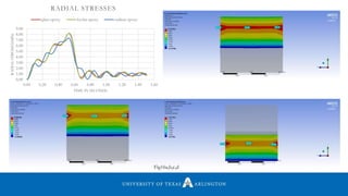
![Analytical calculations for radial ,normal and shear stresses [1]
Fig.6 reference [1]](https://image.slidesharecdn.com/himanshuarunraut-170128030334/85/Static-and-Dynamic-analysis-of-a-composite-leaf-spring-13-320.jpg)
![Reference [2]](https://image.slidesharecdn.com/himanshuarunraut-170128030334/85/Static-and-Dynamic-analysis-of-a-composite-leaf-spring-14-320.jpg)
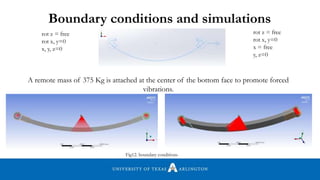
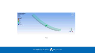
![Meshing has been done by using body sizing and by use of hex dominant method with element
type as all quad. Mid side element nodes are selected to KEPT. This generates a mesh with brick
elements particularly SOLID 186. SOLID186 is a higher order 3-D 20-node solid/brick element.
The middle mesh was generated using sphere of influence[3]
Fig13. Meshing for geometry Fig14. Meshing element reference [3]](https://image.slidesharecdn.com/himanshuarunraut-170128030334/85/Static-and-Dynamic-analysis-of-a-composite-leaf-spring-21-320.jpg)


![2
2.5
3
3.5
4
4.5
1.02 1.021 1.022 1.023 1.024 1.025 1.026 1.027
(σr)max(Mpa)
b/a
DELAMINATION STRESS(σr)max
Fig19. Delamination stresses (σr)max as a function of b/a for β=3.568
Reference [2]](https://image.slidesharecdn.com/himanshuarunraut-170128030334/85/Static-and-Dynamic-analysis-of-a-composite-leaf-spring-30-320.jpg)
![• Experimental study can be performed for the same model to validate the result using 3 point
and 4 point bend set up
• Eye end design can be studied to reduce the chances of local delamination due to
concentration of interlaminar shear stress.[@]
• Hybrid composites can be used as study material for heavy axel loadings
Future Work
Reference [4]
Fig20.](https://image.slidesharecdn.com/himanshuarunraut-170128030334/85/Static-and-Dynamic-analysis-of-a-composite-leaf-spring-31-320.jpg)


![[W f stoecker]_refrigeration_and_a_ir_conditioning_(book_zz.org)](https://cdn.slidesharecdn.com/ss_thumbnails/wfstoeckerrefrigerationandairconditioningbookzz-161019162540-thumbnail.jpg?width=640&height=640&fit=bounds)


