Design Optimization of Front Suspension System of a Heavy Truck using Finite Flement Analysis
•
0 likes•49 views

This document summarizes a study that used finite element analysis to optimize the design of a heavy truck's front suspension system. The original suspension system was modeled in CATIA and imported into HyperMesh for meshing. A harmonic analysis found the system was dynamically stable without resonance. Design optimization was then performed to minimize weight while satisfying structural requirements, resulting in a 45% weight reduction. Von Mises stress and deflection from static, dynamic, and optimized designs were all within allowable limits, confirming the safety of the optimized suspension system under expected loads.

Recommended
Recommended
More Related Content
What's hot
What's hot (20)
Similar to Design Optimization of Front Suspension System of a Heavy Truck using Finite Flement Analysis
Similar to Design Optimization of Front Suspension System of a Heavy Truck using Finite Flement Analysis (20)
More from IRJET Journal
More from IRJET Journal (20)
Recently uploaded
Recently uploaded (20)
Design Optimization of Front Suspension System of a Heavy Truck using Finite Flement Analysis
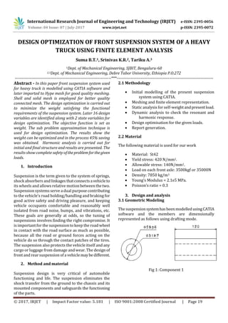
- 1. International Research Journal of Engineering and Technology (IRJET) e-ISSN: 2395-0056 Volume: 04 Issue: 07 | July-2017 www.irjet.net p-ISSN: 2395-0072 © 2017, IRJET | Impact Factor value: 5.181 | ISO 9001:2008 Certified Journal | Page 19 DESIGN OPTIMIZATION OF FRONT SUSPENSION SYSTEM OF A HEAVY TRUCK USING FINITE ELEMENT ANALYSIS Suma B.T.1, Srinivas K.R.2, Tariku A.3 1Dept. of Mechanical Engineering, SJBIT, Bengaluru-60 2,3Dept. of Mechanical Engineering, Debre Tabor University, Ethiopia P.O.272 ---------------------------------------------------------------------***--------------------------------------------------------------------- Abstract - In this paper front suspension system used for heavy truck is modelled using CATIA software and later imported to Hype mesh for good quality meshing. Shell and solid mesh is employed for better quality connected mesh. The design optimization is carried out to minimize the weight satisfying the functional requirements of the suspension system. Later 16 design variables are identified along with 2 state variables for design optimization. The objective function is set as weight. The sub problem approximation technique is used for design optimization. The results show the weight can be optimized and in the process 45% saving was obtained. Harmonic analysis is carried out for initial and final structure and results are presented. The results show complete safety oftheproblemforthegiven loads. 1. Introduction Suspension is the term given to the system of springs, shock absorbers and linkagesthatconnectsavehicleto its wheels and allows relative motionbetweenthetwo. Suspension systems serve a dual purpose contributing to the vehicle's road holding/handling and braking for good active safety and driving pleasure, and keeping vehicle occupants comfortable and reasonably well isolated from road noise, bumps, and vibrations, etc. These goals are generally at odds, so the tuning of suspensions involves finding the right compromise. It is important for the suspension to keep the road wheel in contact with the road surface as much as possible, because all the road or ground forces acting on the vehicle do so through the contact patches of the tires. The suspension also protects the vehicle itself and any cargo or luggage from damage and wear. The design of front and rear suspension of a vehiclemaybedifferent. 2. Method and material Suspension design is very critical of automobile functioning and life. The suspension eliminates the shock transfer from the ground to the chassis and its mounted components and safeguards the functioning of the parts. 2.1 Methodology Initial modelling of the present suspension system using CATIA. Meshing and finite element representation. Static analysis for self-weightandpresentload. Dynamic analysis to check the resonant and harmonic response. Design optimisation for the given loads. Report generation. 2.2 Material The following material is used for our work Material: St42 Yield stress: 420 N/mm2. Allowable stress: 140N/mm2. Load on each front axle: 3500kgf or 35000N Density: 7850 kg/m3 Young’s Modulus = 2.1e5 MPa. Poisson’s ratio = 0.3 3. Design and analysis 3.1 Geometric Modeling The suspensionsystemhasbeenmodelledusingCATIA software and the members are dimensionally represented as follows using drafting mode. Fig 1: Component 1
- 2. International Research Journal of Engineering and Technology (IRJET) e-ISSN: 2395-0056 Volume: 04 Issue: 07 | July-2017 www.irjet.net p-ISSN: 2395-0072 © 2017, IRJET | Impact Factor value: 5.181 | ISO 9001:2008 Certified Journal | Page 20 Fig 2: Component 2 Fig 3: Component 3 Fig 4: Component 4 Fig 5: Component 5 Fig 6: Component 6 Fig 7: Component 7 Fig 8: Component 8 Fig 9: Component 9
- 3. International Research Journal of Engineering and Technology (IRJET) e-ISSN: 2395-0056 Volume: 04 Issue: 07 | July-2017 www.irjet.net p-ISSN: 2395-0072 © 2017, IRJET | Impact Factor value: 5.181 | ISO 9001:2008 Certified Journal | Page 21 Fig 10: Component 10 Fig 11: Component 11 Fig 12: Component 12 Fig 13: Component 13 Fig 14: Component 14 Fig 15: overall Dimensions of the Suspension system Fig 16: 3 Dimensional Modelling of the suspension system Fig 17: Principal View Representation The figure 17 represents the principal views of the problem. The three principal views give the idea of suspension system representation.
- 4. International Research Journal of Engineering and Technology (IRJET) e-ISSN: 2395-0056 Volume: 04 Issue: 07 | July-2017 www.irjet.net p-ISSN: 2395-0072 © 2017, IRJET | Impact Factor value: 5.181 | ISO 9001:2008 Certified Journal | Page 22 3.2 MESHED PLOT: Fig 18: Meshed Plot The figure 18 shows meshed plot of the problem. Total of 8832 elements and 10300nodes are used for representation of the problem. Individual members are shell meshed and later coupled withconstraintand coupling equations. Shell 63 and solid 45 elements are used for representing the shell and solid structure in the problem. The pins are connected using RBE3 element between the members. RBE3 is the best element for load transfer in the finite element problems. 3.3 ELEMENT TYPE USED: 3.3.1 SOLID 45 Element description SOLID45 is used for the 3-D modeling of solid structures. The element is defined by eight nodes having three degrees of freedom at each node: translations in the nodal x, y, and z directions. The element has plasticity,creep,swelling,stressstiffening, large deflection,andlargestraincapabilities.Areduced integration option with hourglass control is available. The elementinputdataincludesfournodes,athickness (for the plane stress option only) and the orthotropic material properties. Orthotropic material directions correspond to the element coordinate directions. Fig 19: solid 45 elements 3.3.2 SOLID 45 Assumptions and Restrictions Zero volume elements are not allowed. Elements may be numbered or may have the planes IJKL and MNOP interchanged. The element may not be twisted such that the element has two separatevolumes.Thisoccurs most frequently when the elements are not numbered properly. All elements must have eight nodes. A prism-shaped element may be formed by defining duplicate K and L and duplicate O and P node numbers (Triangle, Prism and Tetrahedral Elements). A tetrahedron shape is also available. The extrashapes are automatically deleted for tetrahedron elements. 3.3.3 SHELL 63 Element description Fig 20: Shell 63 element SHELL63 hasbothbendingandmembranecapabilities. Both in-plane and normal loads are permitted. The element has six degrees of freedom at each node: translations in the nodal x, y, and z directions and rotations about the nodal x, y, and z-axes. Stress stiffening andlargedeflectioncapabilitiesareincluded. A consistent tangentstiffnessmatrixoptionisavailable for use in large deflection (finite rotation) analyses. The geometry, node locations, and the coordinate system for this element are shown in the above figure. The element is defined by four nodes, fourthicknesses, an elastic foundation stiffness, and the orthotropic material properties. Orthotropic material directions correspond to the element coordinate directions. The element x-axis may be rotated by an angle THETA (in degrees).
- 5. International Research Journal of Engineering and Technology (IRJET) e-ISSN: 2395-0056 Volume: 04 Issue: 07 | July-2017 www.irjet.net p-ISSN: 2395-0072 © 2017, IRJET | Impact Factor value: 5.181 | ISO 9001:2008 Certified Journal | Page 23 The thickness is assumed to vary smoothly over the area of the element, with thethicknessinputatthefour nodes. If the element has a constant thickness, only TK(I) need be input. If the thickness is not constant, all four thicknesses must be input. 3.3.4 SHELL 63 Assumptions The material is assumed to be isotropic and homogeneous Shell and solid meshing is used to represent thin and thick structure Coupling and constraint equationsareusedfor load transfer. All finite element approximations are applicable for the problem. Ansys design optimiser with sub problem approximation is used for design optimisation. 4. Results & Discussion Analysis has been carried out to improve the present suspension system for taking a load to 3.5 ton load or 35000 N load. The member is designed basedonstatic, dynamic strength and later optimized for weight for the given loads. Analysis hasbeencarriedoutbasedon the following cases. a: Analysis for self-weight b. Analysis for Static Strength c: Analysis for Dynamic Strength e: Design Optimization 4.1 SELF WEIGHT ANALYSIS: Many times self-weight plays important role in the structural safety and dynamics. Higher self-weight in the moving vehicles is always undesirable as its gives higher inertia for the problem which requires higher fuel consumption to control the vehicle. So weight should be reduced as much as possible satisfying the functional requirements of the problem. As a start the problem has been analyzed for self-weight to find the stress and deflection. Total Weight of the suspension system: 1167 N or 116.7kgs Fig 21: Deflection due to self-weight The figure 5.1 shows developed displacement in the problem. Maximum deformation is around 1.38 microns or .00138mm or 0.00000138m. Maximum deflection is observed at the leaf spring bottom which will be mounted on the wheel axle transferring the chassis load to the bottom structure. This deflection is very small and indicates the rigidity of the structure. Von Mises stress due to self-weight Fig 22: Von Mises stress due to self-weight The figure 22 shows Von Mises stress developed inthe problem due to self-weight. Self-weightoftheproblem is around 116.7 kgs for the present configuration. The Maximum stress value is around 1.63Mpa and is concentrated in the constraint regions or linking regions. This stress is very small compared to the allowable stress of the structure. So the suspension is safe for the given loads. Generally, Von Mises stress is the most used criteria for finding the failure of the
- 6. International Research Journal of Engineering and Technology (IRJET) e-ISSN: 2395-0056 Volume: 04 Issue: 07 | July-2017 www.irjet.net p-ISSN: 2395-0072 © 2017, IRJET | Impact Factor value: 5.181 | ISO 9001:2008 Certified Journal | Page 24 members. When compared to the other theories of failures, Von Mises match with 90% ductile failures. 4.2 MODAL ANALYSIS: Modal analysis or Eigen value analysis is the most important in finding the dynamic stability of the problems. The dynamic stability is better if the system has better natural or higher natural frequency. If natural frequency is much higher than the operational frequencies, the system will be more stable and static design is enough for the problem. The present design is for maximum speed of the truck of 100 kmph with a wheel diameter of 0.71m. So the operational frequency is as calculated below. Velocity of the truck for 100kmph: V=100000/3600=27.77 m/s V=∏dn n (or) N=27.77/ (∏*d) =27.77/ (3.14*0.71) =12.5cycles/sec or Hz Modal analysis is carriedoutforthesuspensionsystem and results are as follows. The first fundamental frequency for the problem is around 301.13Hz.Sinceoperationalfrequencyismuch smaller than the natural frequency, system is dynamically stable. No possibility of resonance. The mode shapes give idea of weakness of the structure or directional weakness of the structure. Also mode shapes give improper connectivity in the problem along with type of mode. This mode shapes helps in the design of proper constraint. The first fundamental frequency for the problem is around 301.13Hz.Sinceoperationalfrequencyismuch smaller than the natural frequency, system is dynamically stable. No possibility of resonance. The mode shapes give idea of weakness of the structure or directional weakness of the structure. Also mode shapes give improper connectivity in the problem along with type of mode. This mode shapes helps in the design of proper constraint. 4.2.1 Mode Shapes Fig 23: Mode Shape 1 corresponding frequency equal to 301.132 Hz Fig 24: Mode Shape 2 corresponding frequency equal to 442.649 Hz Fig 25: Mode Shape 3 corresponding frequency equal to 494.596 Hz Set No Frequency(Hz) 1 301.13 2 442.65 3 494.6 4 535.68 5 718.06
- 7. International Research Journal of Engineering and Technology (IRJET) e-ISSN: 2395-0056 Volume: 04 Issue: 07 | July-2017 www.irjet.net p-ISSN: 2395-0072 © 2017, IRJET | Impact Factor value: 5.181 | ISO 9001:2008 Certified Journal | Page 25 Fig 26: Mode Shape 4 corresponding frequency equal to 535.682 Hz Fig 27: Mode Shape 5 corresponding frequency equal to 718.057 Hz The observed mode shapes show most of the frequencies create flexural type vibration and weak region is the bottom region shown with red color. The constraint regions are free of vibrations and the unsupported region is having higher deflections. Since operational frequency will never touch even with the first frequency, no chance of higher vibration in the suspension system. 4.3 HARMONIC ANALYSIS: Further harmonic analysis is carried out to find the responseofthesuspensionsystemforthegivenchassis load. The analysis is carried out between 0 to 12.5Hz to find possible higher vibration. Harmonic analysis is mainly carried out to find the frequency response and phase plots. Frequency response helps in finding the displacement at various frequencies and also to find the highest magnitude corresponding to different frequencies. Phase plots helps in finding the level of damping required in the problem. Fig 28: Harmonic Response of the suspension system The figure 28 shows harmonic response of the suspension due to the applied load in the operational range. The graph is showing almost nearing displacementofaround0.1552mmto0.1554mm.Sono resonant frequencies are in the given harmonic range. So this range will not give any problem of resonance in the system. Von Mises stress corresponding to the Harmonic Response Fig 29: Von Mises stress corresponding to the Harmonic Response The figure 29 shows stress generation in the peak harmonic response. Maximum stress value is around 75.5Mpa which is less than the allowable stress of the problem. So structure has the possibility of stress optimization to reduce the weight.
- 8. International Research Journal of Engineering and Technology (IRJET) e-ISSN: 2395-0056 Volume: 04 Issue: 07 | July-2017 www.irjet.net p-ISSN: 2395-0072 © 2017, IRJET | Impact Factor value: 5.181 | ISO 9001:2008 Certified Journal | Page 26 4.4 DESIGN OPTIMIZATION: Design optimisation is very important in the moving structures as it helps in reducing the inertia forces along with less maintenance. Higher inertia forces require higher fuel consumption for higher force generation along high braking requirements. So in the present work, a design optimisation is carried out to minimize the weight satisfying the functional requirements of the suspension system. Design optimiser requires, the parameters should be in scalar form and need of state variables. Here designvariables (DV) are geometrical parameters and state variables (SV) are deflection and stress. Objectivefunction(Obj) need to be selected for proceeding to the design optimisation. In the present problem, objective function is selected as weight. Sub problem approximation is considered for analysis. 4.4.1 Analysis results with present parameters Fig 30: Von Mises Stress with initial configuration The figure 30 shows Von Mises stress of 59.4 Mpa for the initial configuration. The stress is less than the allowable stress of the material. So structure is safe and also maximum deformation is around 0.158mm. Totally 4.4.2 Final set results Fig 31: Final Displacement The figure 31 shows final displacement of 0.465mm in the problem. Maximum displacement is at the middle of the suspension system shown with red color. Since the structure is optimized, the deflection value is increasing compared to the initial configuration. But the developed deflection is less than the allowable deflection so the system is safe for the given loads. Fig 32: Final Von Mises Stress Plot The figure 32 shows final Von Mises stress in the problem. Maximum stress is 109Mpa as shown in the figure. Since this stress islessthantheallowablestress the structure is safe for the given loads. The stresses are mainly limited in the region of connections.
- 9. International Research Journal of Engineering and Technology (IRJET) e-ISSN: 2395-0056 Volume: 04 Issue: 07 | July-2017 www.irjet.net p-ISSN: 2395-0072 © 2017, IRJET | Impact Factor value: 5.181 | ISO 9001:2008 Certified Journal | Page 27 Fig 33: Iterations to Stress development The figure 33 shows stress development with increased number of iterations. The stress keeps varying with iterations and at 4 iteration reaching to the critical stress of 140Mpa. Excepting 1st,4thandlast iterations, the stress value is less than 60Mpa for all iterations. Fig 34: Iterations to Weight variation The figure34showsvariationofweightwithiterations. As iterations increases, the weight of the structure is varying and for initial and final iteration, weight is reducing to the convergence levels. Maximum weight can be observed at 10 th iteration as per thegraph.Only feasible sets are considered for graph representation. Fig.35: Weight to Von Mises stress The figure 35 shows stress variation with weight. Normally weight and stress has inverse relation. I.e. stress will reduce if weight is more as the thickness of the members will be more or vice versa. However, here the stress is maximum when weight in the range of 71 to 74 kgs. Fig 36: Effect of T1, T2, T3, T4 and T5 on Weight
- 10. International Research Journal of Engineering and Technology (IRJET) e-ISSN: 2395-0056 Volume: 04 Issue: 07 | July-2017 www.irjet.net p-ISSN: 2395-0072 © 2017, IRJET | Impact Factor value: 5.181 | ISO 9001:2008 Certified Journal | Page 28 Fig 37: Effect of T6, T7, T8, T9 and T10 on Weight Fig 38: Effect of T11, T12, T13, T14, T15 and T16 on Weight The figures 38 shows influence of design parameters on weight of the suspension system. The weight is mainly influenced by T2, T4, T10, T15, T13, as per the graph. The variation also can be observed through design sets. So the design optimizer helpsthedesigner to select the best set suitable for the manufacturing based on the requirements. The best set is again checked for harmonic loading conditions. The results are as follows Fig 39: Harmonic response The figure 39 showsharmonicresponseforthebestset for the given loads. The graph shows minimum variationofdisplacementsindicatinglittleresponsefor the harmonic loads and also indicates rigidity of the suspension system. The final stress values for harmonic load are represented in the following figure Harmonic stress for the best design set Fig 40: Harmonic stress for the best design set The figure 40 shows maximum stress development of around 127Mpa due to harmonic load. The maximum stress value is around 127Mpa is smaller than the allowable stress of 140Mpa. So the structure will be safe for the given harmonic loads. 5. Conclusions The front suspension system heavy truck is built and analysis for structure safety and design optimization. The overall procedure and summary is as follows. Initially the structure is analyzed for self- weight. The results show little self-weight effects in the suspension system. The suspension is analyzed for dynamic stability through modal analysis. The fundamental natural frequency is much higher than the operational frequency of 12.5Hz, indicating rigidity of the structure for resonance. So suspensionsystem is totallysafe and free from resonance. The analysis with actual loading shows stress development of 59.4Mpa which is small compared to the allowable stress of 140Mpa. So design optimization can be carried out for better structure. Harmonic response is carried out and results shows no resonant forced frequency for the given operational range and stress value is within the allowable limit.
- 11. International Research Journal of Engineering and Technology (IRJET) e-ISSN: 2395-0056 Volume: 04 Issue: 07 | July-2017 www.irjet.net p-ISSN: 2395-0072 © 2017, IRJET | Impact Factor value: 5.181 | ISO 9001:2008 Certified Journal | Page 29 Design optimization is carried out with 16 design variables, 2 state variables and one objective function. The design sets are obtained and results are presented. The design optimizer has given the best weight of 63.5kg out of initial 116 kg. Almost 45% reduction of weight can be obtained from the design optimization process. Further harmonic analysis for the best design set shows, maximum stress of 127 Mpa which is also within the allowable limit of the problem. The results show complete safety of the problem for the given loads. All the results are represented with necessary plots. REFERENCES [1] DouglasW.Blue,”ComputerOptimizationOfHeavy Truck Suspension Parameters” , Road transport technology--4. University of Michigan Transportation Research Institute, Ann Arbor, 1995. [2] Hemin M. Mohyaldeen, “Analysis of an automobile suspension arm using the robust design method”, University Malaysia Pahang, 2011 [3] Dustin A. Boesch, “ Further Improvements to the Truck Model for Road Side Safety Simulation – Suspension and Steering”, 5th European LS-DYNA users Conference,2011 [4] K.Chinna Maddaiah,” Design and Analysis of Automated Truck Cabin Suspension System”, IJESRT, ISSN: 2277-9655, 2013 [5] Domond, K. Brake rotor design and comparison using finite element analysis: an investigation intopology optimization. University of California. Pp.1- 81.,2012 [6] Shantharaja, M., and K. R. Srinivas. "Comparison of Riveted Panel and Integral Panel for Damage Tolerance by Using FEA." International Journal for ScienceandResearch,Volume3Issue9,September 2014: 426-431. [7] Naik, Premkumar, et al. "A Study of Short Areca Fiber and Wood Powder Reinforced Phenol Formaldehyde Composites." American Journal of Materials Science 5.3C (2015): 140-145. [8] Srinivas, K. R., et al. "Experimental Investigation of Mechanical Properties forTamarindShellParticles as Filler in Epoxy Composite." Experimental Investigation of Mechanical Properties for Tamarind Shell Particles as Filler in Epoxy Composite 3.3 (2017). [9] Srinivas, K. R., Premkumar Naik, and B. Somanath. "Experimental Comparison of E-Glass Fiber Reinforced Thermosetting and Thermoplastic Composites for Tensile Strength." International Journal for Scientific Research and Development. Volume-3 Issue-9, Nov. 2015 [10] Somanath, B., et al. "Differential Evolution and Simulated Annealing Technique for Design and Developing of Process Plan to Perform Optimization on Finite Capacity Scheduling for Simultaneous System of Machines." (2017). Volume:04 Issue:03. www.irjet.net