Download as PDF, PPTX


![Result
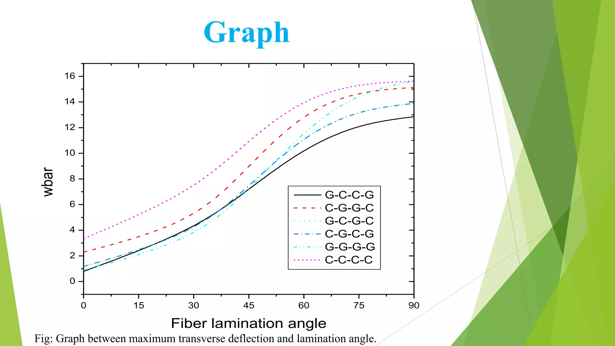
Wbar for different material arrangement
ARRANGEMENT
LAMINATION ANGLE
G-C-C-G C-G-G-C G-C-G-C C-G-C-G G-G-G-G C-C-C-C
[±0]
0.7918 2.2911 1.1768 1.1768 0.8892 3.3476
[±30]
3.9791 4.5605 3.6844 3.6844 3.2126 6.9985
[±45]
7.2019 9.0034 7.4395 7.4395 7.0851 11.0671
[±60]
10.4028 13.2527 11.414 11.414 11.8315 14.3012
[±75]
12.2993 14.8525 13.401 13.401 14.7884 15.4477
[±90]
12.8528 15.1215 13.8788 13.8788 15.625 15.625
Maximum deflection of simply supported composite beam at different lamination angle for
different combination of composite material.](https://image.slidesharecdn.com/effectoflaminationangleonmaximumdeflectionofsimplysupportedcompositebeam-171015231830/75/Effect-of-lamination-angle-on-maximum-deflection-of-simply-supported-composite-beam-18-2048.jpg)


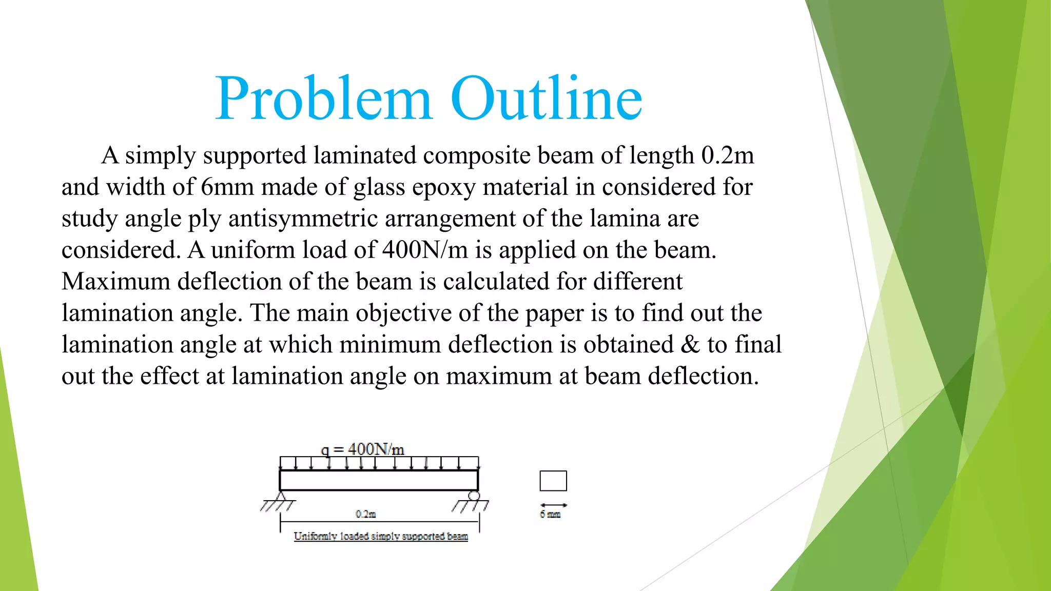
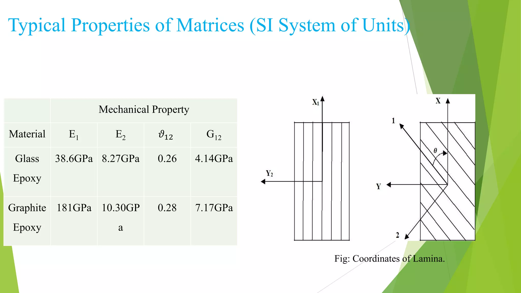
The seminar report investigates the impact of lamination angles on the maximum deflection of simply supported composite beams, specifically made of glass-epoxy materials. It details the methods used for analysis, including classical laminated beam theory and MATLAB simulations, and finds that the g-c-c-g arrangement of composite materials yields the minimum transverse deflection. Conclusions drawn highlight the effectiveness of this arrangement in practical applications and suggest future studies to explore variations in beam types and loading conditions.


