Downloaded 1,213 times
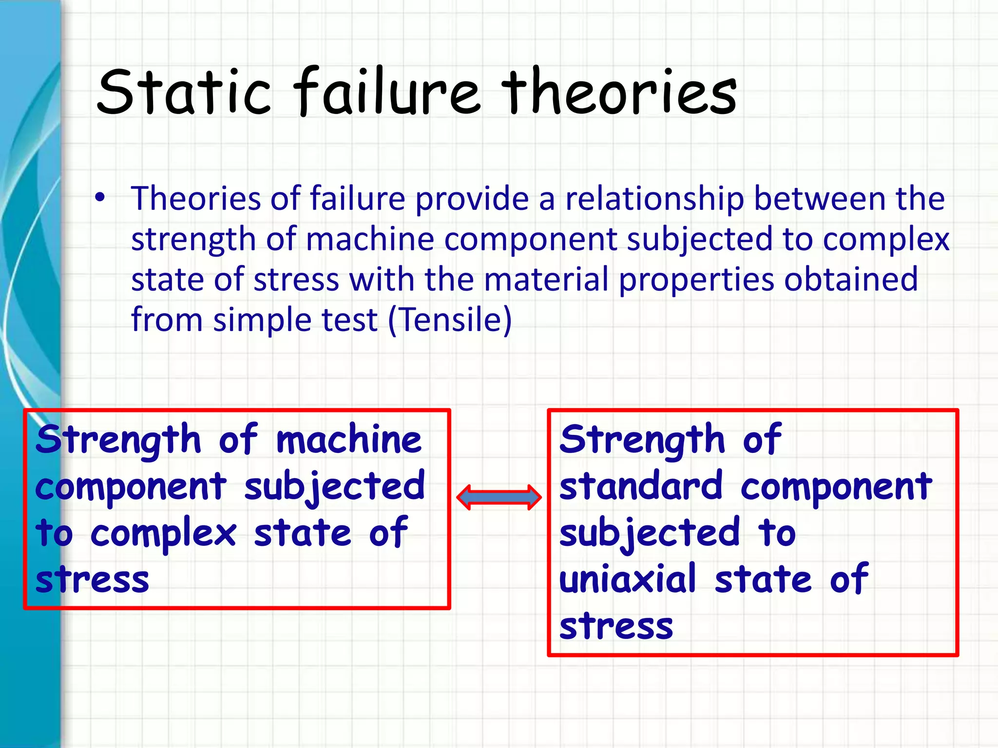
![Static failure theories
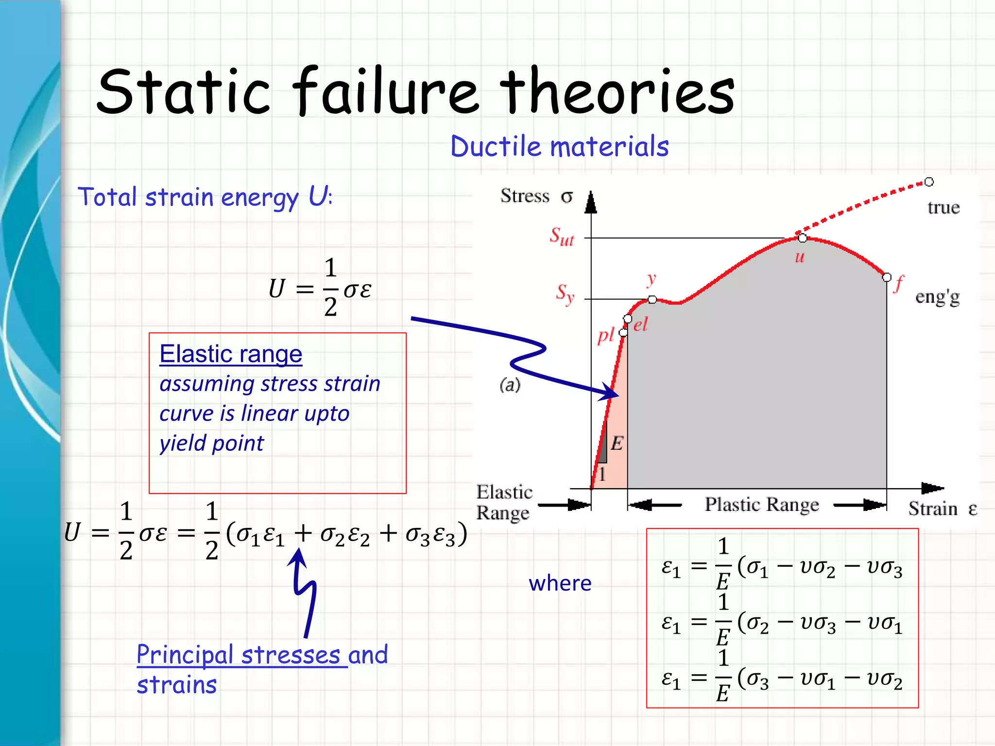
Ductile materials: total strain energy
Using previous expressions, total energy is:
𝑈 =
1
2
𝜎𝜀 =
1
2𝐸
[𝜎1
2
+ 𝜎2
2
+ 𝜎3
2
− 2𝜐(𝜎1 𝜎2 + 𝜎2 𝜎3 + 𝜎3 𝜎1)
which can be expressed as 𝑈 = 𝑈ℎ + 𝑈 𝑑
Hydrostatic energy Deformation energy
𝑈ℎ =
3
2
(1 − 2𝜐)
𝐸
𝜎ℎ
2
𝜎ℎ =
𝜎1 + 𝜎2 + 𝜎3
3
Obtained by setting:
𝑈ℎ = 𝑈(𝜎1 = 𝜎2 = 𝜎3 = 𝜎ℎ)
𝑈 𝑑 =
1 + 𝜐
3𝐸
[𝜎1
2 + 𝜎2
2 + 𝜎3
2
−(𝜎1 𝜎2 + 𝜎2 𝜎3 + 𝜎3 𝜎1)]
Obtained by setting:
𝑈 𝑑 = 𝑈 − 𝑈ℎ](https://image.slidesharecdn.com/1staticfailuretheories-ductiler1-150823214204-lva1-app6892/75/1-static-failure-theories-ductile-r1-23-2048.jpg)
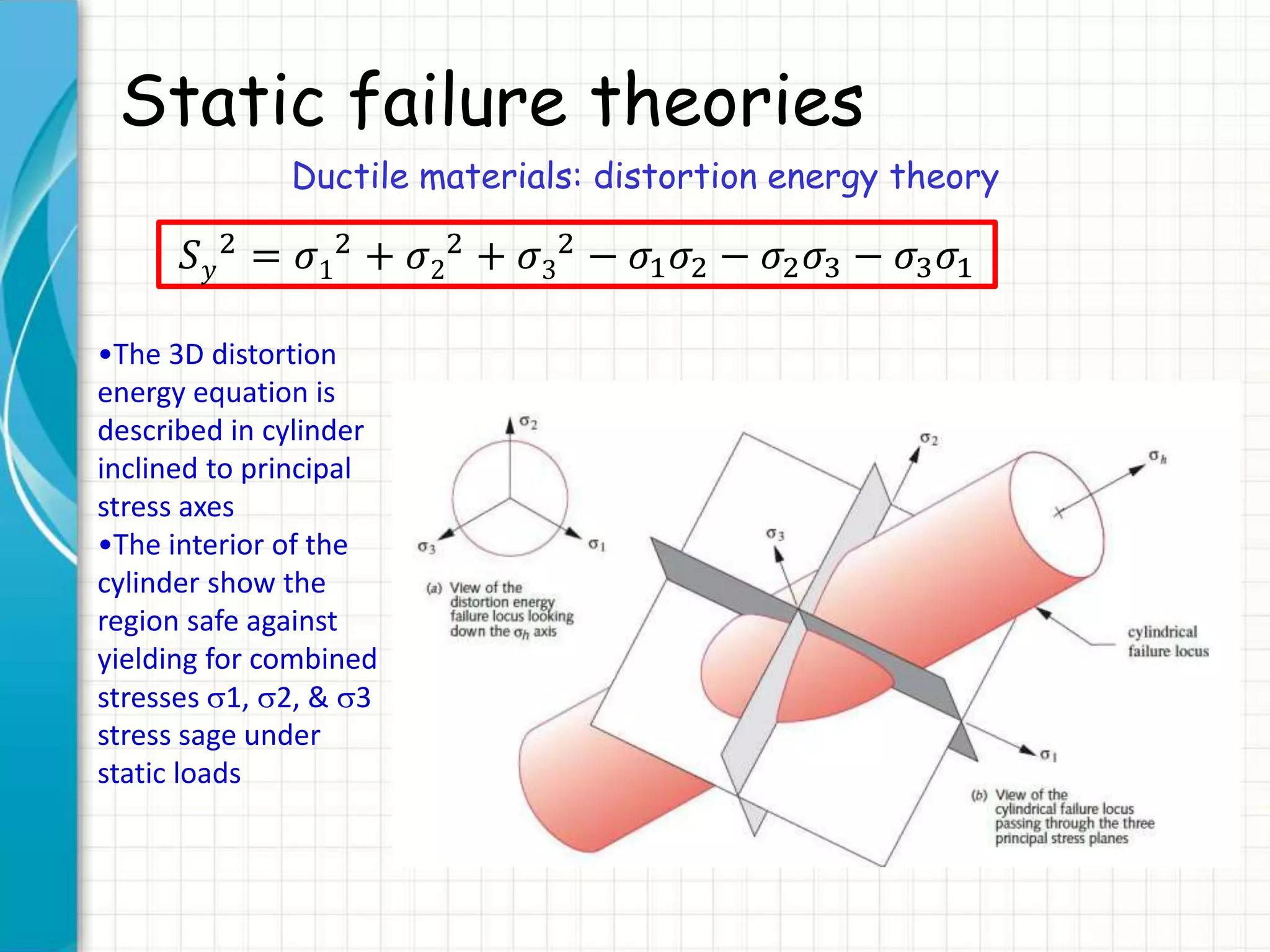
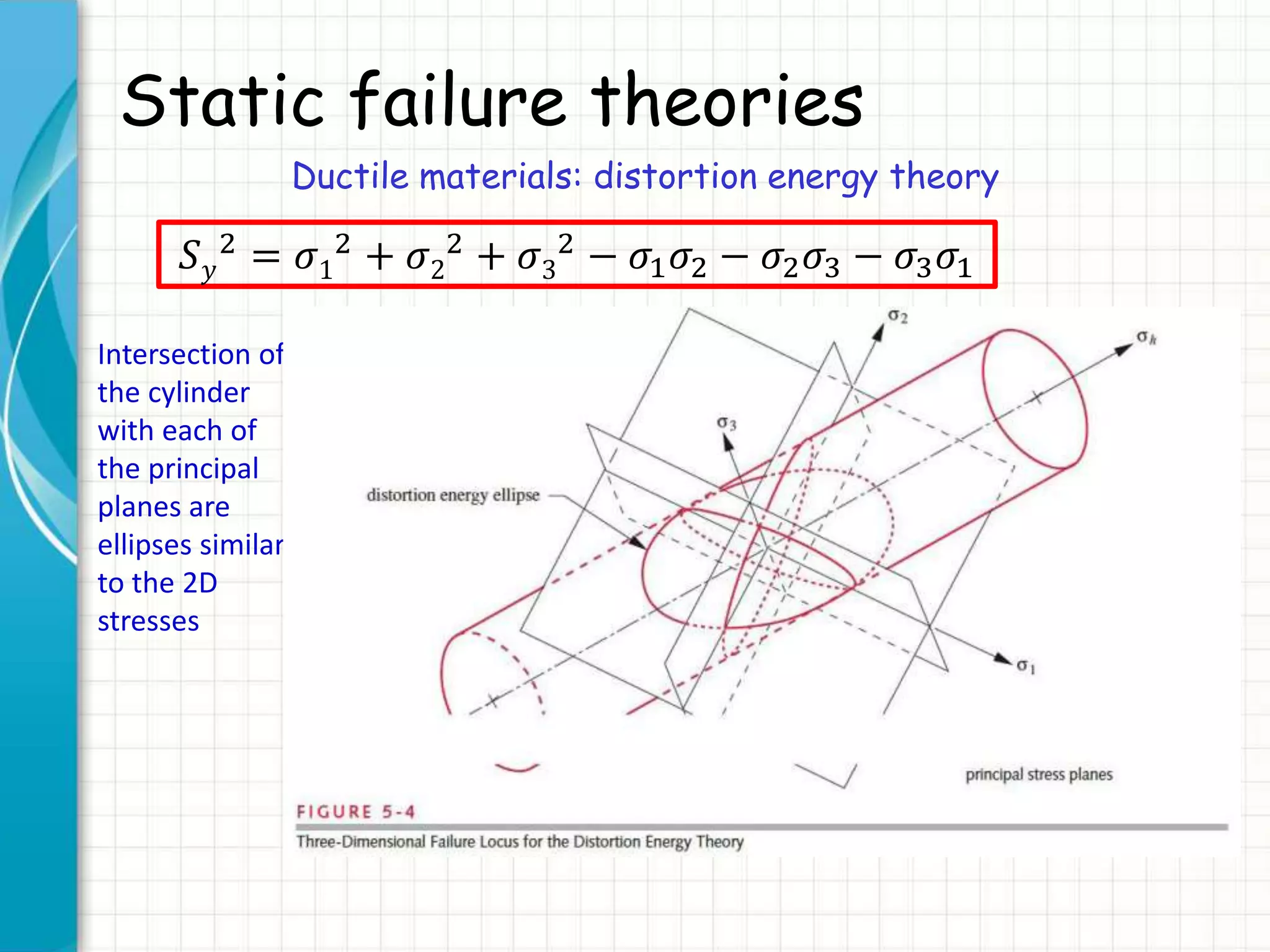
![Static failure theories
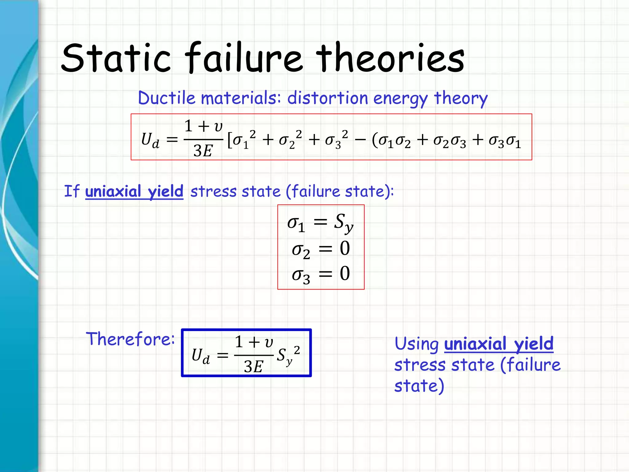
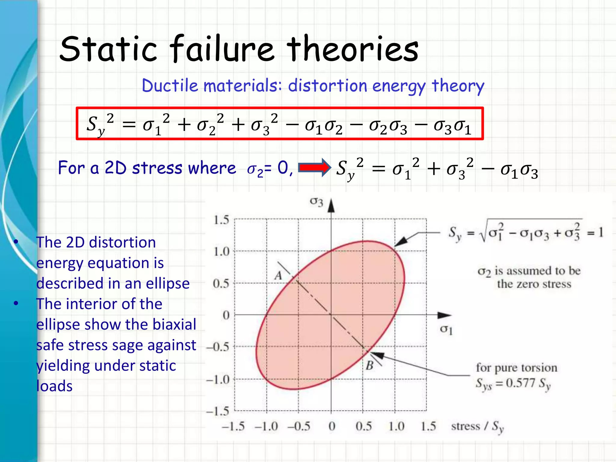
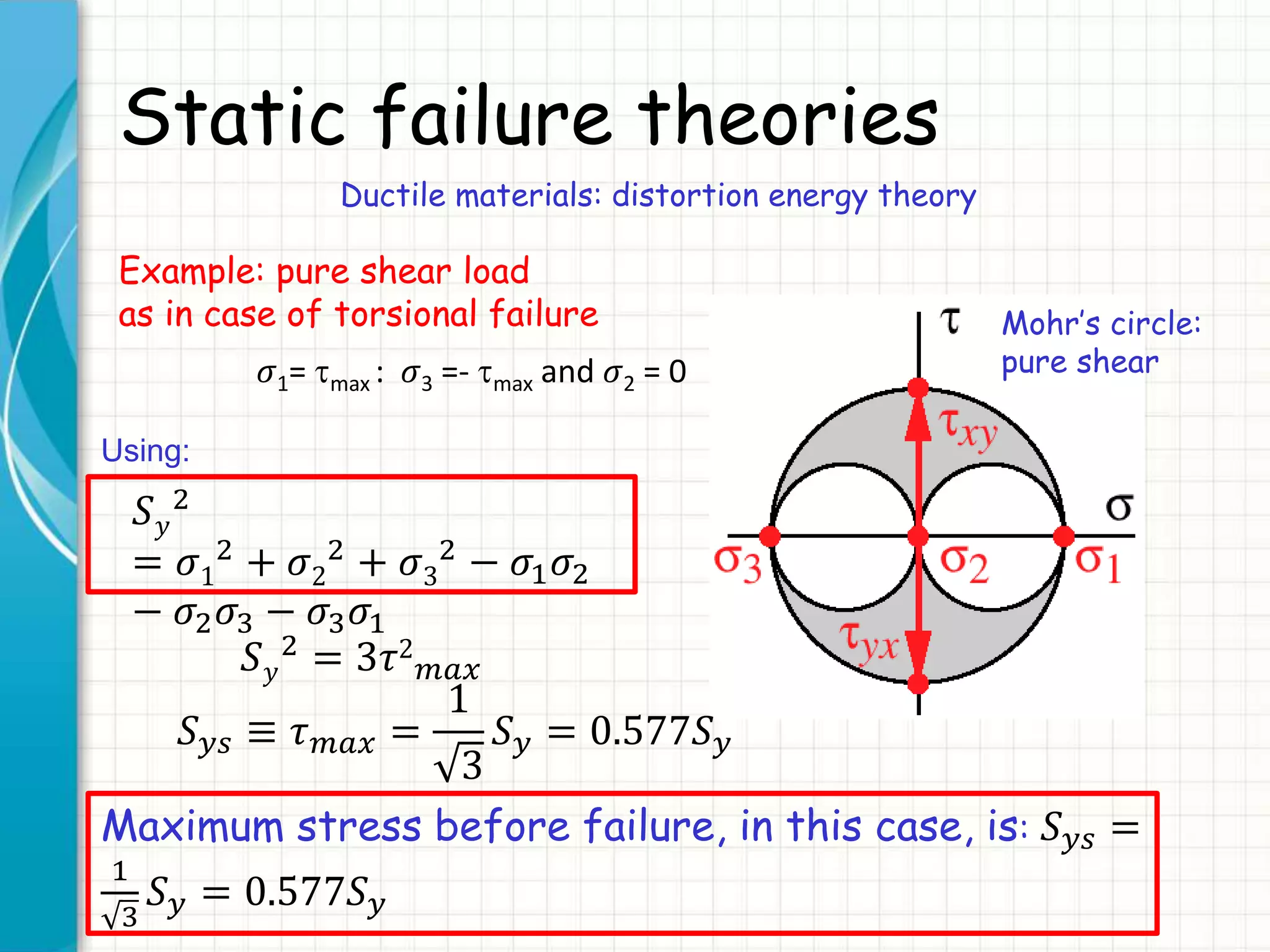
Ductile materials: distortion energy theory
𝑈 𝑑 =
1 + 𝜐
3𝐸
[𝜎1
2 + 𝜎2
2 + 𝜎3
2 − 𝜎1 𝜎2 + 𝜎2 𝜎3 + 𝜎3 𝜎1 ]
For any other state of stresses:
Failure criterion is obtained by setting:
1 + 𝜐
3𝐸
[𝜎1
2
+ 𝜎2
2
+ 𝜎3
2
− (𝜎1 𝜎2 + 𝜎2 𝜎3 + 𝜎3 𝜎1] ≤
1 + 𝜐
3𝐸
𝑆 𝑦
2
Distortion energy:
uniaxial stress at
yield
Distortion energy:
any other state of
stresses
𝜎1
2 + 𝜎2
2 + 𝜎3
2 − 𝜎1 𝜎2 − 𝜎2 𝜎3 − 𝜎3 𝜎1 ≤ 𝑆 𝑦
2](https://image.slidesharecdn.com/1staticfailuretheories-ductiler1-150823214204-lva1-app6892/75/1-static-failure-theories-ductile-r1-25-2048.jpg)
![Static failure theories
Ductile materials: distortion energy theory
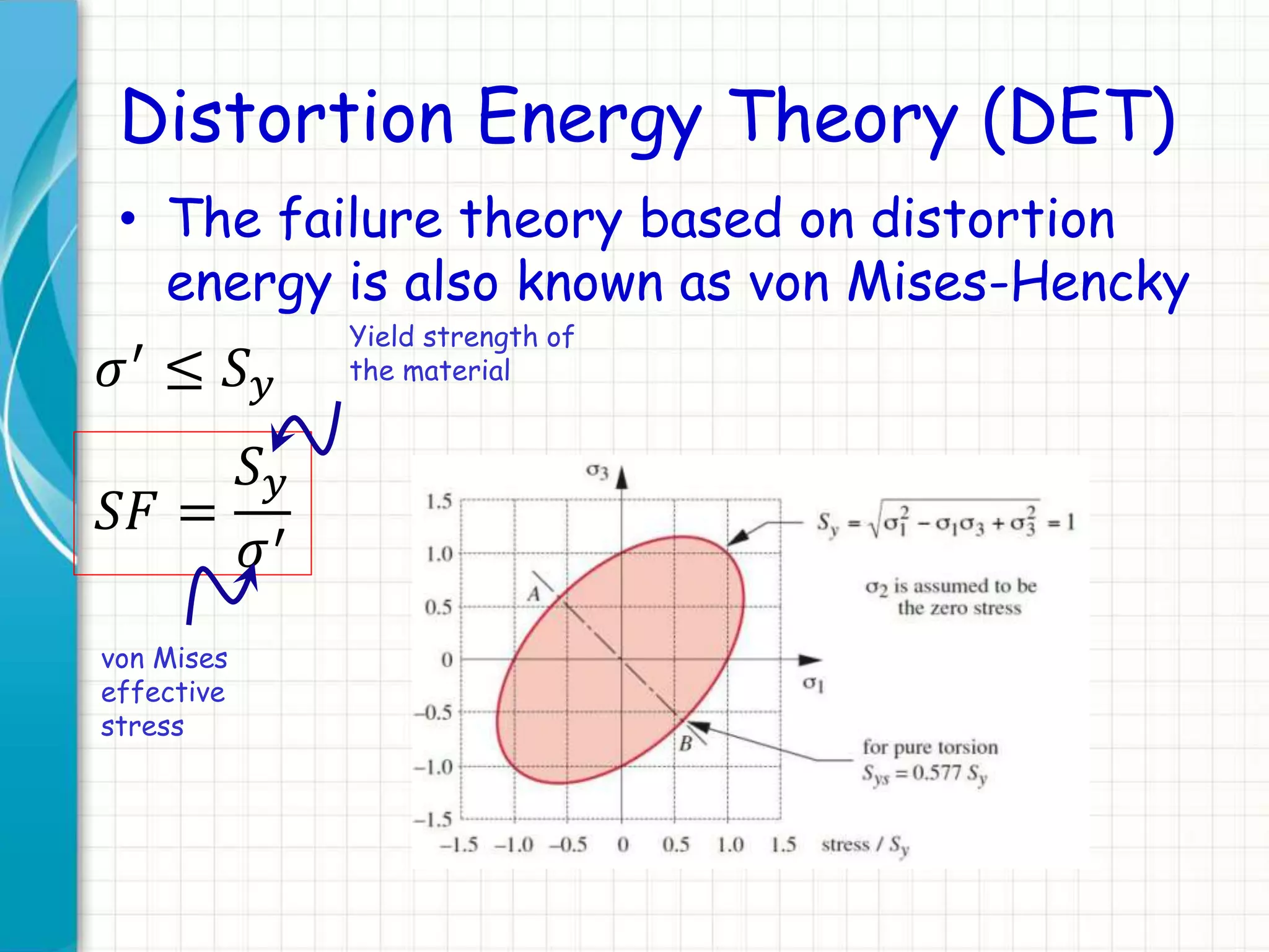
Von Mises effective stress
𝑆 𝑦
2 = [𝜎1
2 + 𝜎2
2 + 𝜎3
2 − 𝜎1 𝜎2 − 𝜎2 𝜎3 − 𝜎3 𝜎1] ≡ 𝜎′ 2
Definition:
𝜎′ = 𝜎1
2
+ 𝜎2
2
+ 𝜎3
2
− 𝜎1 𝜎2 − 𝜎2 𝜎3 − 𝜎3 𝜎1
(Yield surface)
von Mises effective stress
von Mises effective stress: uniaxial stress that would create the
same distortion energy as is created by actual combination of
applied stresses](https://image.slidesharecdn.com/1staticfailuretheories-ductiler1-150823214204-lva1-app6892/75/1-static-failure-theories-ductile-r1-29-2048.jpg)
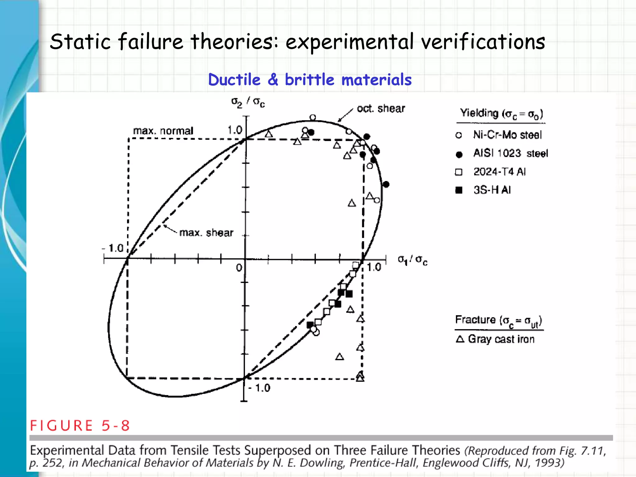
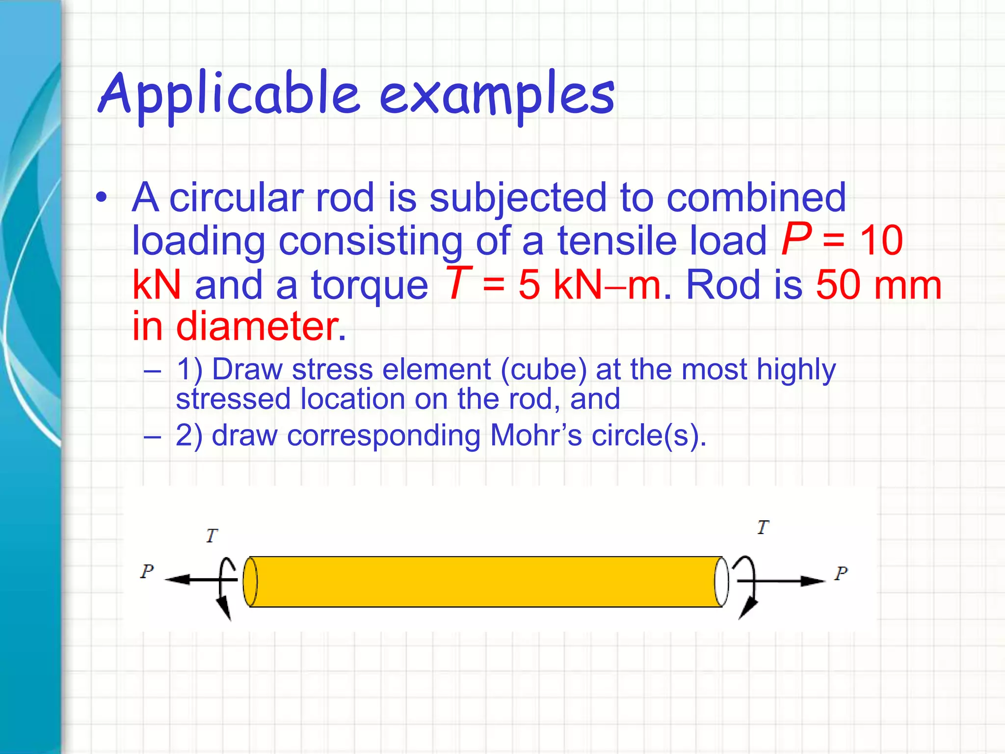
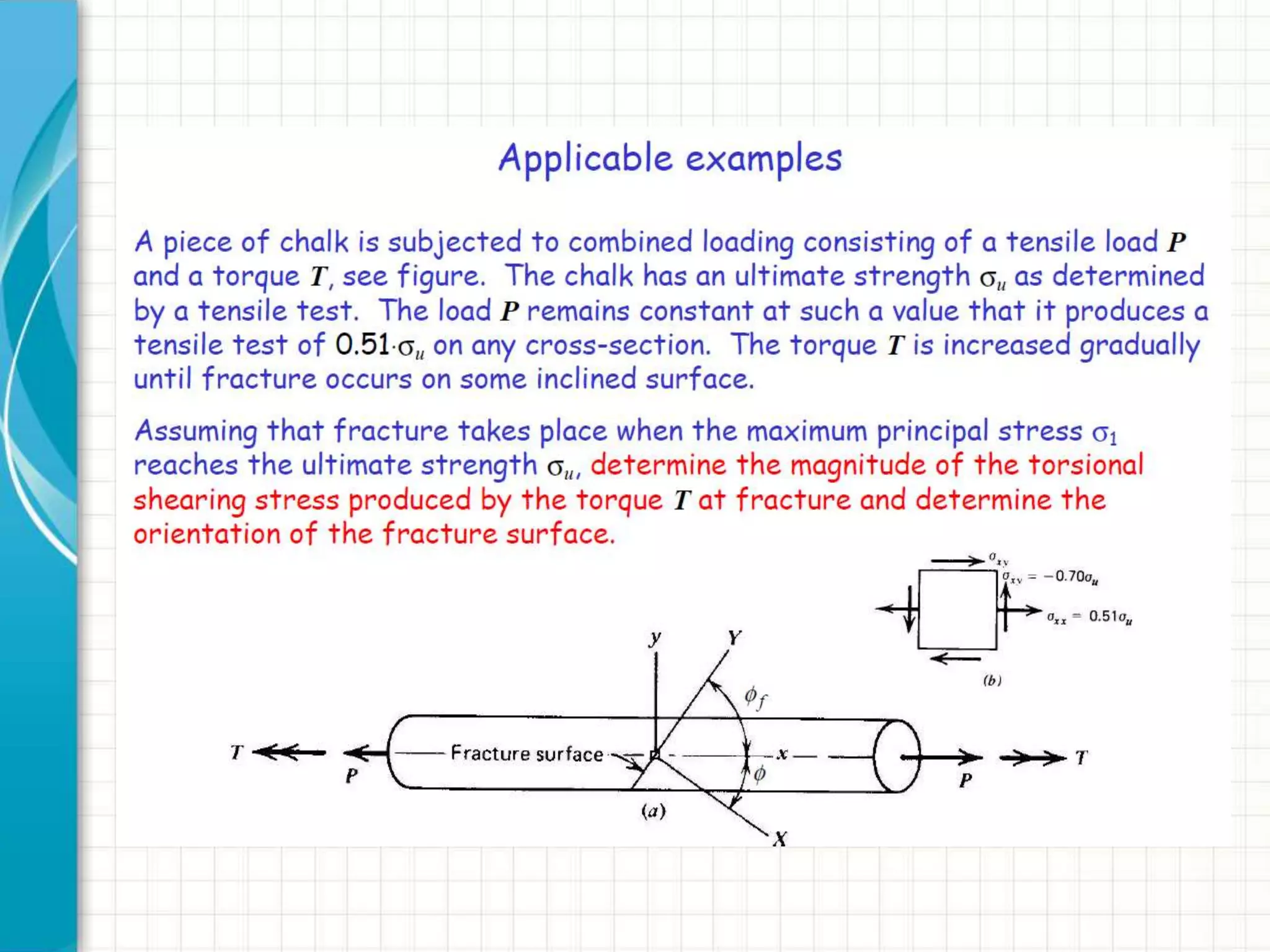
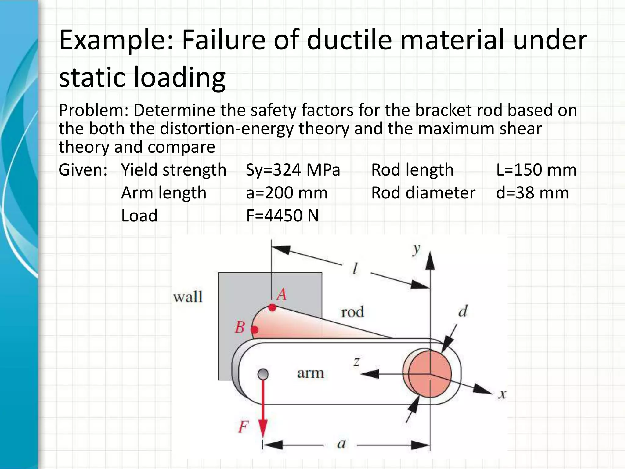

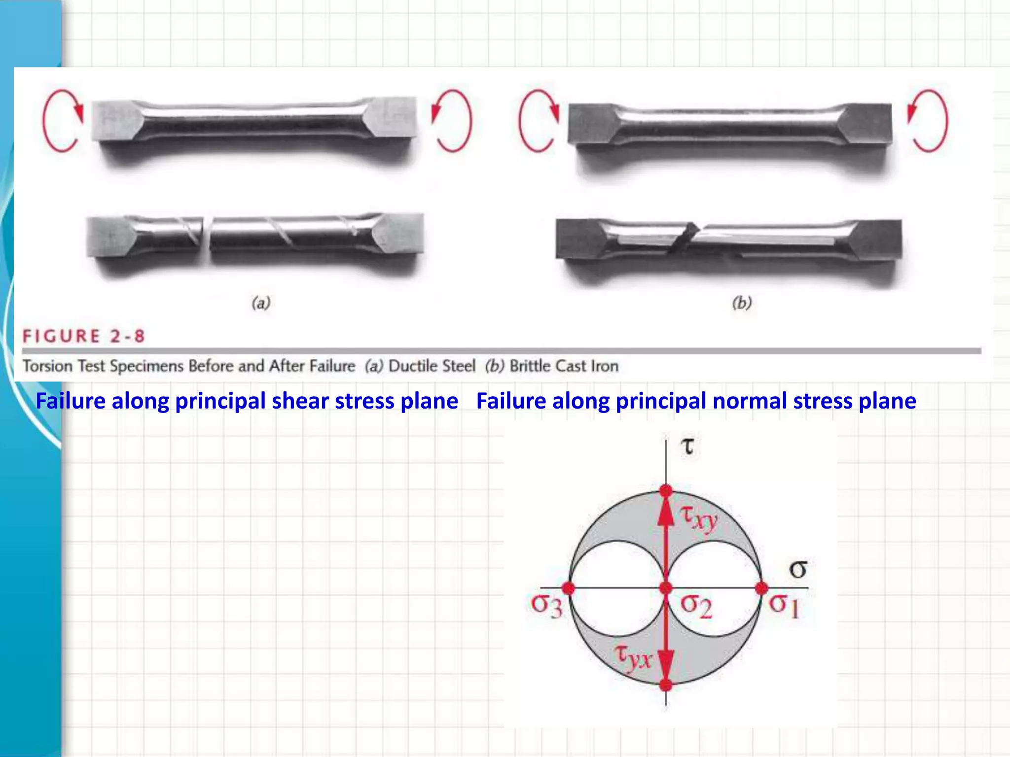
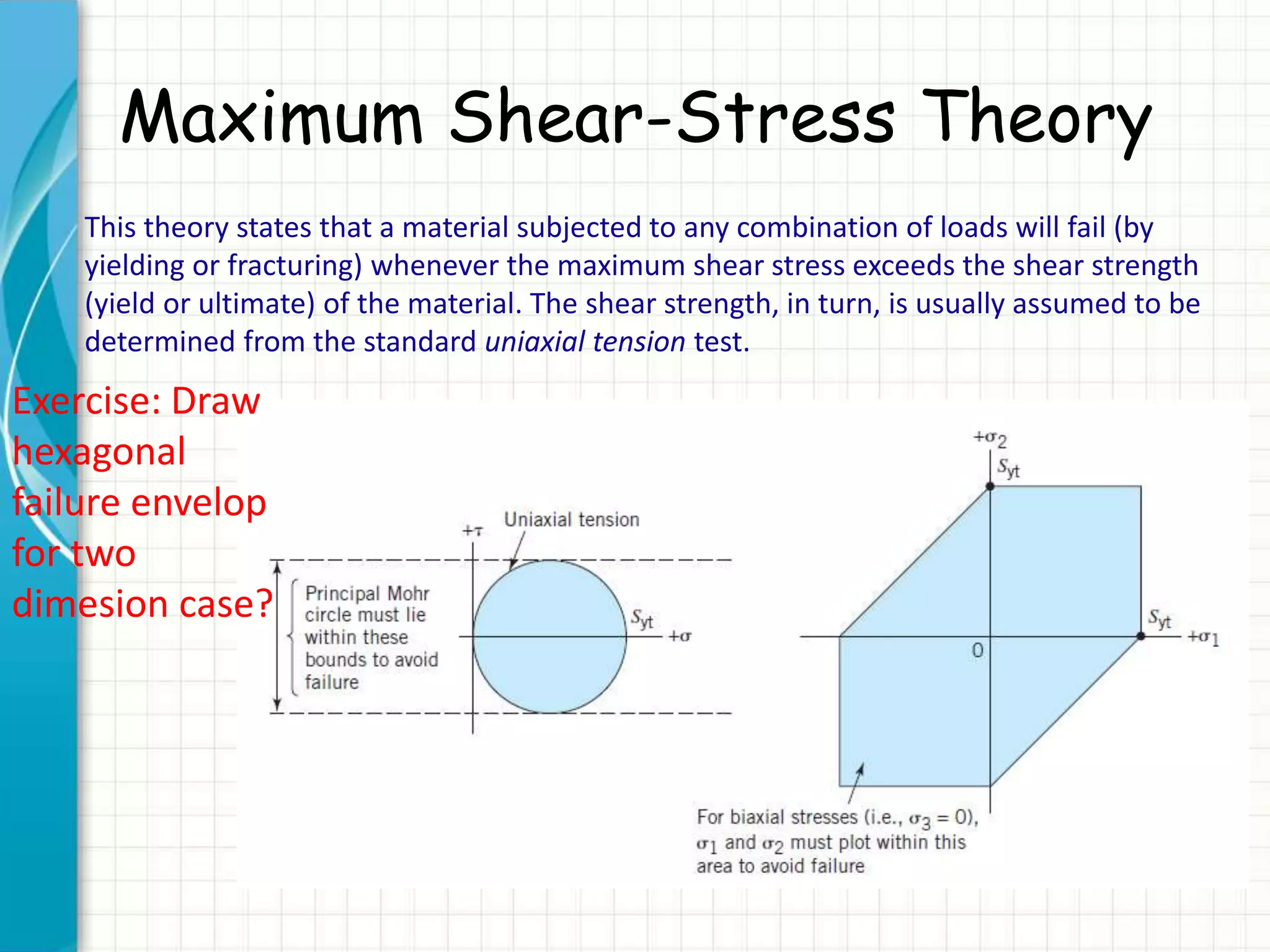
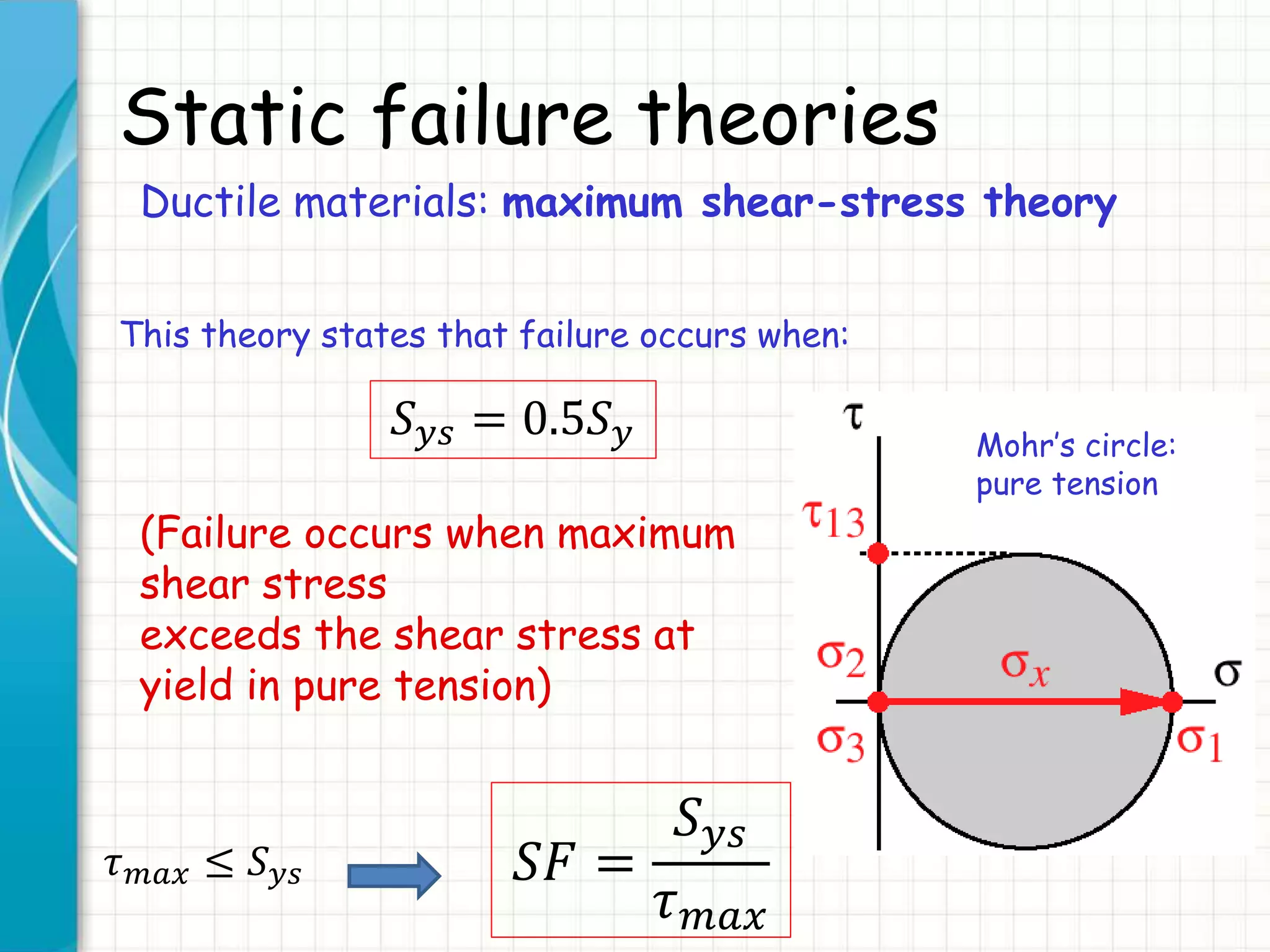
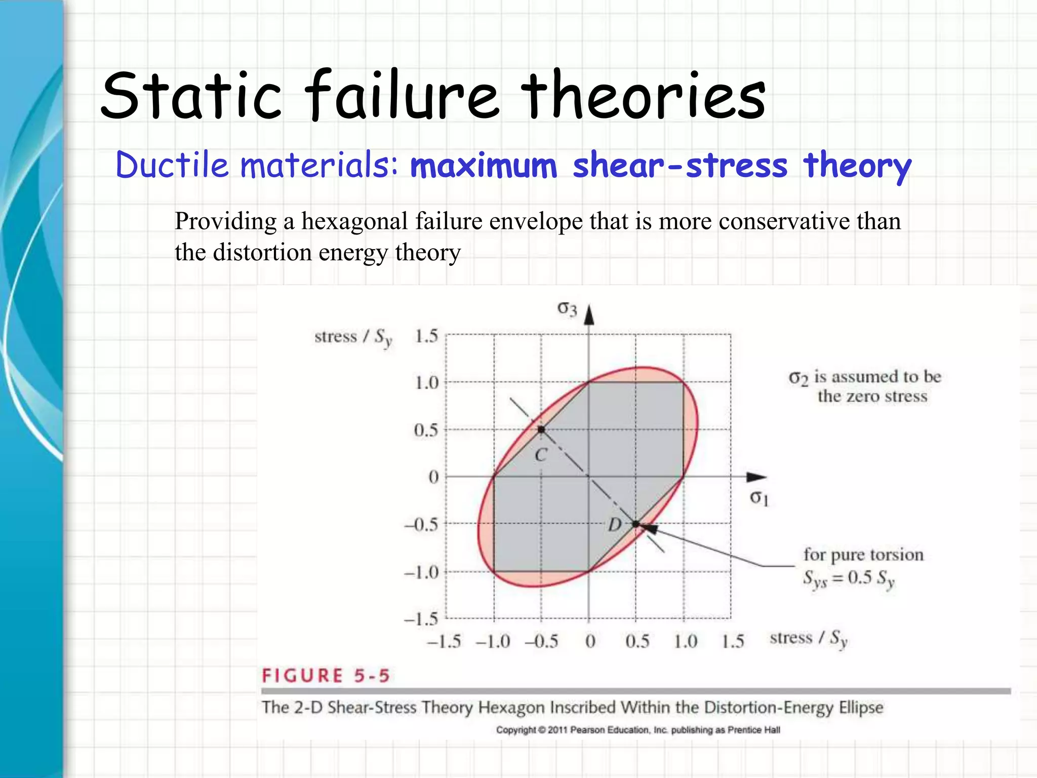
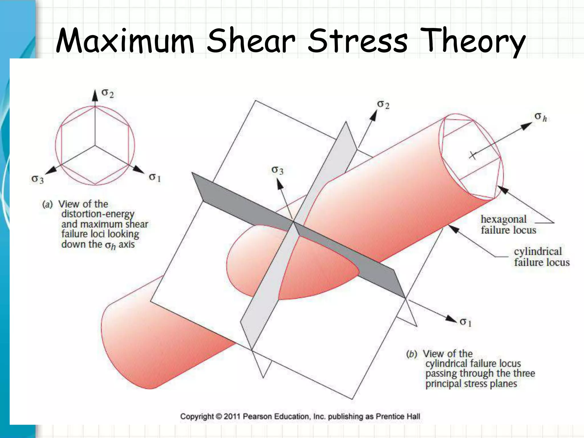
This document discusses static failure theories for analyzing machine components under loading. It begins by asking why parts fail and explaining that failure depends on the material properties and type of loading. It then covers different failure modes and the need for separate theories for ductile and brittle materials. The key static failure theories presented are maximum normal stress theory, maximum shear stress theory, distortion energy theory, and their applications to ductile and brittle materials. Examples are provided to illustrate Mohr's circle analysis and applying the theories.


