SlideShare a Scribd company logo
cc
–Introduction
–Types of springs
–spring material
–Stress in helical springs
–Design of helical Compression Spring
–Deign of Helical Tensile spring
Design of Helical Torsion Spring
CHAPTER 4.Mechanical Springs
4.1 Introduction
Mechanical Springs
– Springs are flexible bodies (generally metal) that can be
twisted, pulled, or stretched by some force, and can
return to their original shape when the force is released.
– These devices allow controlled application of force or
torque, and the storing and release of energy can be
another purpose.
Springs give a relatively large elastic deflection.
Application of springs
• To apply forces and controlling motion, as in brakes and
clutches.
• Measuring forces, as in the case of a spring balance.
• Storing energy, as in the case of springs used in watches and toys.
• Reducing the effect of shocks and vibrations in vehicles and
machine foundations
Flexibility is sometimes needed and is often provided by metal bodies
with cleverly controlled geometry. Such flexibility can be linear or
nonlinear in relating deflection to load.
These devices allow controlled application of force or torque; the
storing and release of energy can be another purpose
In general, spring may be classified as:
1. Wire springs such as helical springs of round
or square wire, made to resist and deflect
under tensile, compressive, and torsional
loads.
2. Flat springs which includes cantilever and
elliptical types, wound motor-or clock- type
power springs, a flat spring washers, usually
called Belleville springs.
3. Special-shaped springs
4.2 Types of springs
Helical compression Types of Springs(1)
Figure 4.1a
Helical tensile and torsional Types of Springs
(2)
Figure 4.1b
Some Types of Springs (3)
Figure 4.1c
Some Types of Springs (4)
Figure 4.1d
4.3. Spring Materials
• Springs are manufactured either by hot- or cold-
working processes, depending upon the size of the
material, the spring index, and the properties desired.
• In general, pre hardened wire should not be used if D/d
< 4 or if d > 14 in.
• Winding of the spring induces residual stresses through
bending, but these are normal to the direction of the
torsional working stresses in a coil spring.
• Quite frequently in spring manufacture, they are
relieved, after winding, by a mild thermal treatment.
• A great variety of spring materials are available
to the designer, including plain carbon steels,
alloy steels, and corrosion-resisting steels, as well
as nonferrous materials such as phosphor
bronze, spring brass, beryllium copper, and
various nickel alloys.
• Descriptions of the most commonly used steels
will be described below
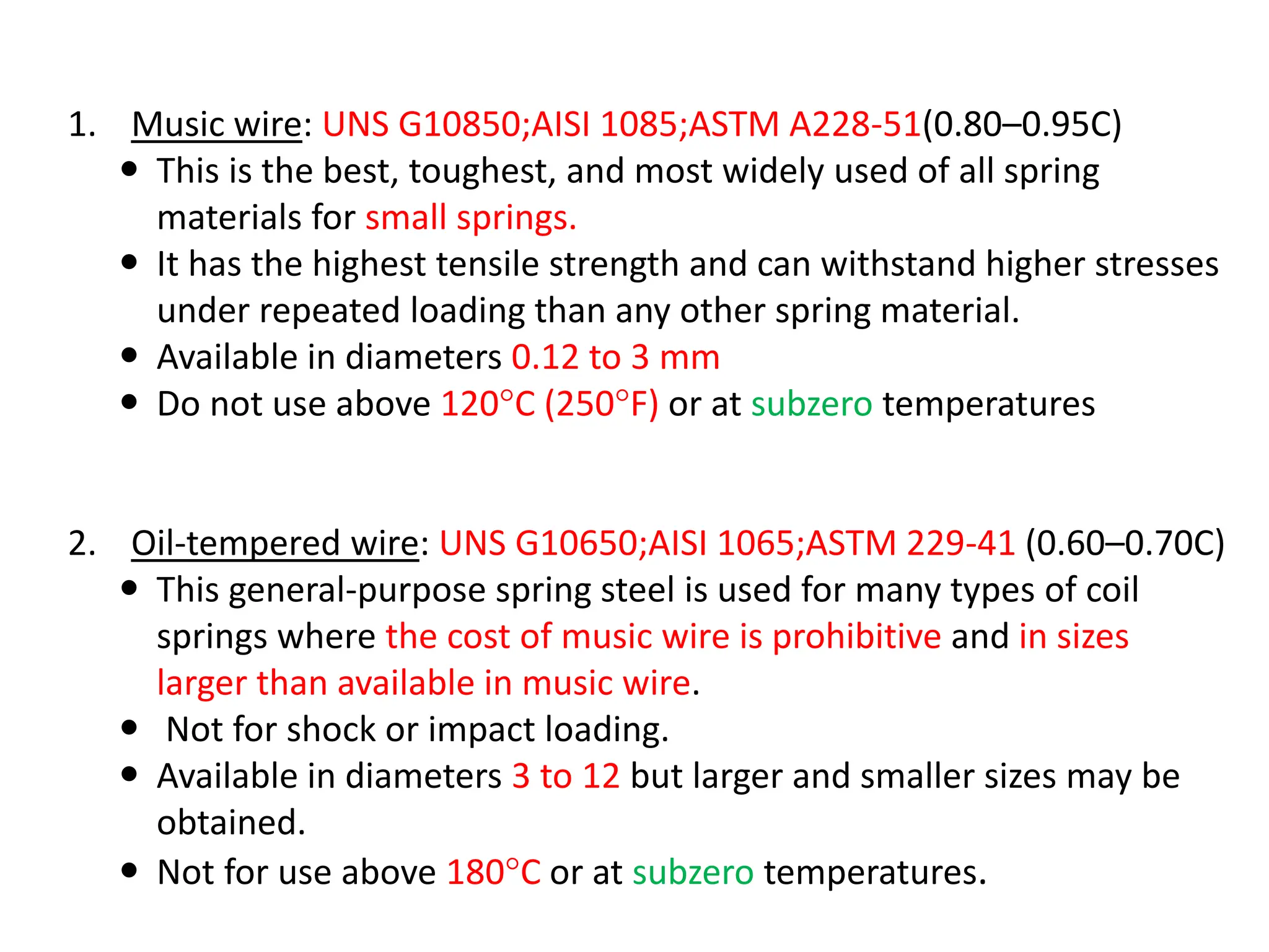
1. Music wire: UNS G10850;AISI 1085;ASTM A228-51(0.80–0.95C)
 This is the best, toughest, and most widely used of all spring
materials for small springs.
 It has the highest tensile strength and can withstand higher stresses
under repeated loading than any other spring material.
 Available in diameters 0.12 to 3 mm
 Do not use above 120°C (250°F) or at subzero temperatures
2. Oil-tempered wire: UNS G10650;AISI 1065;ASTM 229-41 (0.60–0.70C)
 This general-purpose spring steel is used for many types of coil
springs where the cost of music wire is prohibitive and in sizes
larger than available in music wire.
 Not for shock or impact loading.
 Available in diameters 3 to 12 but larger and smaller sizes may be
obtained.
 Not for use above 180°C or at subzero temperatures.
3. Hard-drawn wire: UNS G10660;AISI 1066;ASTM A227-47 (0.60–0.70C)
– This is the cheapest general-purpose spring steel and should be used
only where life, accuracy, and deflection are not too important.
– Available in diameters 0.8 to 12 mm .
– Not for use above 120°C (250°F) or at subzero temperatures.
4. Chrome-vanadium: UNS G61500;AISI 6150;ASTM 231-41
 This is the most popular alloy spring steel for conditions involving
higher stresses than can be used with the high-carbon steels and for
use where fatigue resistance and long endurance are needed.
 Also good for shock and impact loads.
 Widely used for aircraft-engine valve springs and for temperatures to
220°C.
 Available in annealed or pre-tempered sizes 0.8 to 12 mm in diameter.
5. Chrome-silicon : UNS G92540; AISI 9254
 This alloy is an excellent material for highly stressed springs that
require long life and are subjected to shock loading.
 Rockwell hardnesses of C50 to C53 are quite common, and the material
may be used up to 250°C .
 Available from 0.8 to 12 mm in diameter
 Spring materials may be compared by an examination of their tensile
strengths; these vary so much with wire size that they cannot be
specified until the wire size is known.
 The material and its processing also, of course, have an effect on
tensile strength. Hence, the approximate equation which is useful to
estimating minimum tensile strengths is
4-1
where the intercept A and the slope m are on the graph of tensile strength
versus wire diameter and, can be obtained in Table 4–1.
Material ASTM
No
Expone
nt m
Diameter,
in
A, Kpsi
.inm
Diameter,
mm
A, MPa,
mmm
Music wire A228 0.145 0.004–
0.256
201 0.10-6.5 2211
Hard-drawn
wire
A227 0.190 0.028–
0.500
140 0.7–12.7 1783
Chrome-
vanadium
wire
A232 0.168 0.032-
0.437
169 0.8-11.1 2005
Table 4–1Constants A and m of Sut = A/dm for Estimating Minimum Tensile Strength wires
4.4. Design of compression Helical Springs
• A helical compression spring is an open-pitch spring
which is used to resist applied compression forces or to
store energy, and is applicable: Ball point pens, Pogo
sticks, Valve assemblies in engines
• A round-wire helical compression spring loaded by the
axial force F is shown in figure 4-2a.
Figure 4–2
(a) Axially loaded helical spring;
(b) (b) free-body diagram showing that
the wire is subjected to a direct
shear and a torsional shear.
4.4.1. Stresses in Helical Springs
Two important parameters in spring
design:
1. The mean coil diameter D
2. The wire diameter d.
 If the spring is cut at some point, the
effect of the removed portion replaced
by the net internal reactions. See figure
4-2b or 4-3.
 Using the equation of equilibrium, the
cut portion would contain a direct shear
force F and a torsion T=FD/2
Figure 4.3
 The maximum stress in the wire may be computed by superposition of the
direct shear and torsional shear stress.
 The result is at the inside fiber of the spring.
4-2
 Substitution of
4-3
 Define the spring index, C=D/d,
which is a measure of coil curvature.
With this relation, Eq. (4-3)
can be rearranged to give
4-4
where Ks is a shear-stress correction
factor and is defined by the equation
4-5
 For most springs, C ranges from about 6 to 12. 16
=
4.4.2.The Curvature Effect
• Above equation is based on the wire being straight. However, the curvature of
the wire increases the stress on the inside of the spring but decreases it only
slightly on the outside.
 important in fatigue because the loads are lower and there is no opportunity for localized
yielding.
 Less important for static loading (but dynamic fatigue loading), ….. strain-strengthening with
the first application of load .
• Unfortunately, it is necessary to find the curvature factor in a roundabout way.
• The Bergsträsser the curvature correction factor is followed, i.e.
4-6
• Now, Ks , KB , and Kc are simply stress correction factors applied multiplicatively to
Tr/J at the critical location to estimate a particular stress.
• There is no stress concentration factor.
• In this course we will use τ = KB(8FD)/(πd3) to predict the largest shear stress.
While constant KB can be obtained & Kw Whal factor
4-7
17
4.4.3. Deflection of Helical Springs
Castigliano’s Theorem
• A most unusual, powerful, and often surprisingly
simple approach to deflection analysis is afforded
by an energy method called Castigliano’s
theorem. It is a unique way of analyzing
deflections and is even useful for finding the
reactions of indeterminate structures.
• Castigliano’s theorem states that when forces
act on elastic systems subject to small
displacements, the displacement corresponding to
any force, in the direction of the force, is equal to
the partial derivative of the total strain energy
with respect to that force.
F
u
y



i.e
19
 There fore, the deflection-force relations are quite easily obtained by using
Castigliano’s theorem
 The total strain energy for a helical spring is composed of a torsional
component and a shear component. Thus strain energy can be approximated:
 Substituting T = FD/2, l = πDN,
J = πd4/32, and A = πd2/4 results in
where N = Na = number of active coils.
Then using second theory of Castigliano’s
to find total deflection y gives
Since C = D/d, can be
rearranged to yield
The spring rate, also called the scale of the
spring, k = F/y, can be obtained from above
equation
4.4.4 Compression Springs and its ends
• The four types of ends generally used for
compression springs are illustrated in Fig. 4–4.
• A spring with plain ends has a non interrupted
helicoid; the ends are the same as if a long spring
had been cut into sections.
• A spring with plain ends that are squared or
closed is obtained by deforming the ends to a
zero-degree helix angle.
• Springs should always be both squared and
ground for important applications, because a
better transfer of the load is obtained.
Figure 4–4
Types of
ends for
compression
springs:
(a) both ends
plain;
(b) both ends
squared;
(c) both
ends squared
and ground;
(d) both ends
plain and
ground
Table 4–2
Formulas for the
Dimensional
Characteristics of
Compression-Springs.
(Na = Number of
active Coils)
4.4.5 Stability
• compression coil springs may buckle when
the deflection becomes too large. The critical
deflection is given by the equation
effective slenderness ratio
4-15
4-14
Failure craiterea δ>ycrt
4-15a
4.4.6 Helical Compression Spring Design for Static Service
Design Considerations
 Taking into consideration that with the lower indexes being more
difficult to form a compression spring i.e. because of the danger of
surface cracking and springs with higher indexes tending to tangle
often enough to require individual packing, the preferred range of
spring index is 4 ≤ C ≤ 12.
 The recommended range of active turns is 3 ≤ Na ≤ 15.
 A helical coil spring force-deflection characteristic is ideally linear.
 The designer confines the spring’s operating point to the central 75
percent of the curve between no load, F = 0, and closure,
F = Fs .
24
 Thus, the maximum operating force should be limited to
Fmax ≤ 7/8 Fs .
 Defining the fractional overrun to closure as ξ, it is
recommended that ξ ≥ 0.15
 Recommended factor of safety at closure (solid height) is
ns ≥ 1.2
◊ Set removal or presetting, which is a process used in the
manufacture of compression springs to induce useful residual
stresses.
 Set removal increases the strength of the spring and so is
especially useful when the spring is used for energy-
storage purposes.
 However, set removal should not be used when springs
are subject to fatigue.
fractional overrun , ξ,
ξ =1/7=0.143 .=0.15 it is better ξ>=0.15
4-16
4-17
4-18
Figure of merit=fom
some recommended design conditions
4-2
4-2
4-2
4-19
4.4.7 Critical Frequency of Helical
Springs
• When helical springs are used in applications
requiring a rapid reciprocating motion, the
designer must be certain that the physical
dimensions of the spring are not such as to
create a natural vibratory frequency close to
the frequency of the applied force; otherwise
resonance may occur, resulting in damaging
stresses.
where k = spring rate g = acceleration due to gravity
l = length of spring W = weight of spring
x = coordinate along length of spring u = motion of any particle at distance x
4-20
Wolford and Smith show that
the frequency where the spring
has one end against a flat plate
and the other end free
fundamental
frequency in hertz
The weight of the active
part of a helical spring
The governing equation for the
translational vibration of a
spring is the wave equation:
4.4.8 Fatigue Loading of Helical
Compression Springs
• Helical springs are never used as both compression
and extension springs. This is because they are
usually assembled with a preload so that the working
load is additional. Thus, the spring application fall
under the condition of fluctuating loads.
• Springs are almost always subject to fatigue loading.
In many instances the number of cycles of required
life may be small, say, several thousand But the
valve spring of an automotive engine must sustain
millions of cycles of operation without failure; so it
must be designed for infinite life.
To improve the fatigue strength of dynamically loaded
springs, shot peening can be used.
It can increase the torsional fatigue strength by 20
percent or more.
Shot size is about 1 /64 in, so spring coil wire diameter
and pitch must allow for complete coverage of the
spring surface.
The best data on the torsional endurance limits of
spring steels are those reported by Zimmerli.
He discovered the surprising fact that size, material,
and tensile strength have no effect on the
endurance limits (infinite life only) of spring steels in
sizes under 3 /8 in (10 mm).
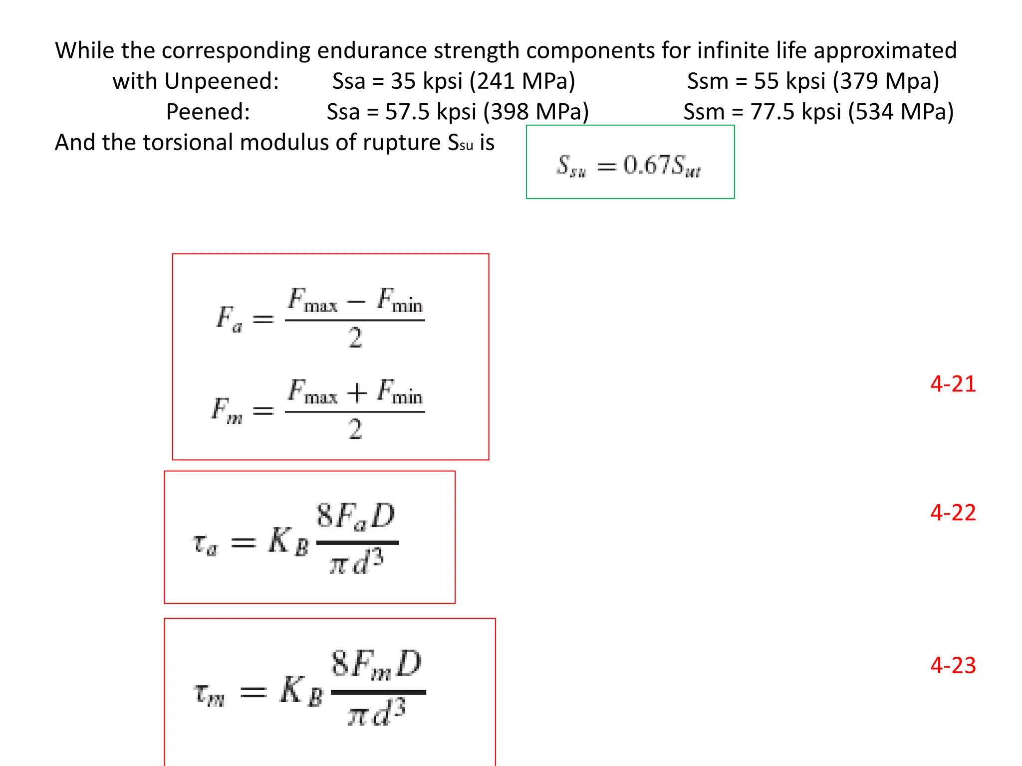
While the corresponding endurance strength components for infinite life approximated
with Unpeened: Ssa = 35 kpsi (241 MPa) Ssm = 55 kpsi (379 Mpa)
Peened: Ssa = 57.5 kpsi (398 MPa) Ssm = 77.5 kpsi (534 MPa)
And the torsional modulus of rupture Ssu is
4-21
4-22
4-23
4.5 TENSION HELICAL SPRING
• Helical tension/extension springs store energy and exert a pulling force.
– It has some means of transferring the load from the support to the body by means
of some arrangement. Hook Shaped end
– They have various types of end hooks or loops by which they are attached to
the loads.
• They are usually made from round wire and are close-wound with initial
tension.
– Most extension springs are made with the body coils held tightly together by a
force called initial tension. The measure of initial tension is the load required to
overcome the internal force and start coil separation.
• Like compression springs, extension springs are stressed in torsion in the
body coils.
35
Figure 4-3 Helical Tension Spring
Figure 4.6 helical
tensile spring
4.5.1. EXTENSION SPRINGS AND ITS END
• Extension springs differ from compression springs in that they carry tensile
loading, they require some means of transferring the load from the
support to the body of the spring
– The load transfer can be done with a threaded plug or a swivel hook
• Types of ends used on extension springs.
Figure 4-4 Types of ends used on extension springs.
36
Figure 4.7 Types of ends used on extension springs
Terminology
• The free length L0 of a spring measured inside the end loops or
hooks as shown in Fig.4-6 can be expressed as
4-24
where D is the mean coil diameter, Nb is the number of body
coils, and C is the spring index.
• The equivalent number of active helical turns Na ordinary
twisted end loops as shown in Fig. 4-6 , can be approximated
by
4-25
where G and E are the shear and tensile moduli of elasticity,
respectively.
37
•Applicable: Garage door assemblies, Vise-grip pilers, carburetors
4.5.2 initial tension
• The initial tension in an extension
spring is created in the winding
process by twisting the wire as it is
wound onto the mandrel.
• The amount of initial tension that a
spring maker can routinely
incorporate is as shown in Fig. 4-8
• The preferred range can be
expressed in terms of the
uncorrected torsional stress τi as
where C is the spring index
38
Figure 4-8 Torsional stresses due to initial
tension as a function of spring index C in
helical extension springs.
4.5.3. Allowable strength
• Guidelines for the maximum allowable corrected stresses for static
applications of extension springs are given in Table 4-3
Table 4-3 Maximum Allowable Stresses for Helical Extension Springs in Static
Applications
39
Table 4-3 Maximum Allowable Stresses for Helical Extension Springs in Static Applications
• The above information is based on a stress-ratio of R = τmin/ τ max = 0.
– For this case, τ a = τ m = τ max/2.
• Hence, we have to label the strength values of Table 4-4 as Sr for bending
or Ssr for torsion
Where : Ssa = Ssm = Ssr /2 , and
Sr = 0.45Sut
40
Table 4-4 Maximum Allowable Stresses for ASTM A228 and Type 302 Stainless Steel
Helical Extension Springs in Cyclic Applications
4.5.3. Stresses in tensile Helical Springs
• Stresses in the body of the extension spring are handled the same as
compression springs. In designing a spring with a hook end, bending and
torsion in the hook must be included in the analysis.
• In Fig.4-8a and b a commonly used method of designing the end is shown.
41
Figure 4-9 Ends for extension springs. (a) Usual design; stress at A is due to combined
axial force and bending moment. (b) Side view of part a; stress is mostly torsion at B.
• The maximum tensile stress at A from Figure 4-9, due to bending and axial
loading, is given by
4-26
where (K)A is a bending stress correction factor for curvature, given by
4-27
• The maximum torsional stress at point B is given by
4-28
where the stress correction factor for curvature, (K)B, is
4-29
42
4.6. TORSION HELLICAL SPRING
• Torsional helical springs are used in door hinges, automobile starters, Mouse
tracks, Rocker switches, Clipboards and for any application where torque is
required
 Helical springs that exert a torque or store rotational energy are known as
torsion springs.
 Torsion springs are used in spring-loaded hinges, oven doors, clothespins,
window shades, ratchets, counterbalances, cameras, door locks, door checks,
and many other applications.
 The ends of the spring are attached to other application objects, so that if
the object rotates around the center of the spring, it tends to push the
spring to retrieve its normal position.
43
Figure 4-10 Torsion spring
4.6.1Types of ends for Tensional springs:
The End Location
• In specifying a torsion spring, the ends must be located relative to each
other.
• Commercial tolerances on these relative positions are listed in Table 4-5.
• The simplest scheme for expressing the initial unloaded location of one
end with respect to the other is in terms of an angle β defining the partial
turn present in the coil body as Np = β/360◦, as shown in Fig. 4-11.
44
Figure . 4-11.
Table 4-5
• The number of body turns Nb is the number of turns in the free spring
body by count. The body-turn count is related to the initial position angle
β by
• where Np is the number of partial turns. The above equation means that
Nb takes on non integer, discrete values such as 5.3, 6.3, 7.3, . . . , with
successive differences of 1 as possibilities in designing a specific spring.
45
4-30
4.6.2Bending Stress
• A torsion spring has bending induced in the coils, rather than torsion. This
means that residual stresses built in during winding are in the same
direction but of opposite sign to the working stresses that occur during
use.
• The bending stress can be obtained from curved-beam theory expressed
in the form
where K is a stress-correction fator.
• The value of K depends on the shape of the wire cross section and
whether the stress sought is at the inner or outer fiber.
where C is the spring index and the subscripts i and o refer to the inner and
outer fibers, respectively. The approximate bending stress for a round-wire
torsion spring.
46
4-32
4-31
4-33
Example 4.1
A helical compression spring is made of no. 16 music wire. The
outside coil diameter of the spring is 7/16 in. The ends are
squared and there are 25/2 total turns.
(a) Estimate the torsional yield strength of the wire.
(b) Estimate the static load corresponding to the yield strength.
(c) Estimate the scale of the spring.
(d) Estimate the deflection that would be caused by the load in
part (b).
(e) Estimate the solid length of the spring.
( f ) What length should the spring be to ensure that when it is
compressed solid and then released, there will be no
permanent change in the free length?
(g) Given the length found in part ( f ), is buckling a possibility?
(h) What is the pitch of the body coil?
4-1
4-1
4-7
T4-2
4-12
4-2
above
4.2
4-15a
END

More Related Content

Similar to Chapter 4 Mechanical Spring (2).pptx

Unit 4-springs
Unit 4-springsUnit 4-springs
Unit 4-springs
Chandra Kumar S
 
DESIGN OF MACHINE ELEMENTS
DESIGN OF MACHINE ELEMENTSDESIGN OF MACHINE ELEMENTS
DESIGN OF MACHINE ELEMENTS
SIVASHANKAR N
 
Unit 2 Shafts and Coupling.pptx
Unit 2 Shafts and Coupling.pptxUnit 2 Shafts and Coupling.pptx
Unit 2 Shafts and Coupling.pptx
Charunnath S V
 
G1303034650
G1303034650G1303034650
G1303034650
IOSR Journals
 
Danke Power Report
Danke Power ReportDanke Power Report
Danke Power ReportPriten Vasa
 
Lecture 3.pdf
Lecture 3.pdfLecture 3.pdf
Lecture 3.pdf
KarimSamhy1
 
Engineering science lesson 6 2
Engineering science lesson 6 2Engineering science lesson 6 2
Engineering science lesson 6 2
Shahid Aaqil
 
Revised ppt for Design of energy storing elements and engine componentsxx
Revised ppt for Design of energy storing elements and engine componentsxxRevised ppt for Design of energy storing elements and engine componentsxx
Revised ppt for Design of energy storing elements and engine componentsxx
KAMARAJ COLLEGE OF ENGINEERING AND TECHNOLOGY
 
2022-23 project review.pptx
2022-23 project review.pptx2022-23 project review.pptx
2022-23 project review.pptx
ramana4uiitm
 
ASSIGNMENT 1 PPT TYMEB136.pptx
ASSIGNMENT 1 PPT TYMEB136.pptxASSIGNMENT 1 PPT TYMEB136.pptx
ASSIGNMENT 1 PPT TYMEB136.pptx
LEGENDARYTECHNICAL
 
Pressure vessels
Pressure vesselsPressure vessels
Pressure vessels
Abdul Hannan
 
Lec12 Continuous Beams and One Way Slabs(2) Columns (Reinforced Concrete Desi...
Lec12 Continuous Beams and One Way Slabs(2) Columns (Reinforced Concrete Desi...Lec12 Continuous Beams and One Way Slabs(2) Columns (Reinforced Concrete Desi...
Lec12 Continuous Beams and One Way Slabs(2) Columns (Reinforced Concrete Desi...
Hossam Shafiq II
 
DESIGN OF RIVETED JOINTS.pptx
DESIGN OF RIVETED JOINTS.pptxDESIGN OF RIVETED JOINTS.pptx
DESIGN OF RIVETED JOINTS.pptx
PraveenK19954
 
Poros
PorosPoros
Poros
stnto212
 
SEMINAR @Design And Analysis Of A Connecting Rod With Different Materials
SEMINAR @Design And Analysis Of A Connecting Rod     With Different MaterialsSEMINAR @Design And Analysis Of A Connecting Rod     With Different Materials
SEMINAR @Design And Analysis Of A Connecting Rod With Different Materials
Dr.M BALA THEJA
 
SHAFTS And Its Mechanical Properties.pptx
SHAFTS And Its Mechanical Properties.pptxSHAFTS And Its Mechanical Properties.pptx
SHAFTS And Its Mechanical Properties.pptx
Raphael666601
 
Unit 2 design of shaft
Unit 2 design of shaftUnit 2 design of shaft
Unit 2 design of shaft
Somnath Kolgiri
 
Unit 2 Design Of Shafts Keys and Couplings
Unit 2 Design Of Shafts Keys and CouplingsUnit 2 Design Of Shafts Keys and Couplings
Unit 2 Design Of Shafts Keys and Couplings
Mahesh Shinde
 
Unit 2 torsion and springs
Unit  2 torsion and springsUnit  2 torsion and springs
Unit 2 torsion and springs
karthi keyan
 

Similar to Chapter 4 Mechanical Spring (2).pptx (20)

Unit 4-springs
Unit 4-springsUnit 4-springs
Unit 4-springs
 
DESIGN OF MACHINE ELEMENTS
DESIGN OF MACHINE ELEMENTSDESIGN OF MACHINE ELEMENTS
DESIGN OF MACHINE ELEMENTS
 
Unit 2 Shafts and Coupling.pptx
Unit 2 Shafts and Coupling.pptxUnit 2 Shafts and Coupling.pptx
Unit 2 Shafts and Coupling.pptx
 
G1303034650
G1303034650G1303034650
G1303034650
 
Danke Power Report
Danke Power ReportDanke Power Report
Danke Power Report
 
Lecture 3.pdf
Lecture 3.pdfLecture 3.pdf
Lecture 3.pdf
 
An24266270
An24266270An24266270
An24266270
 
Engineering science lesson 6 2
Engineering science lesson 6 2Engineering science lesson 6 2
Engineering science lesson 6 2
 
Revised ppt for Design of energy storing elements and engine componentsxx
Revised ppt for Design of energy storing elements and engine componentsxxRevised ppt for Design of energy storing elements and engine componentsxx
Revised ppt for Design of energy storing elements and engine componentsxx
 
2022-23 project review.pptx
2022-23 project review.pptx2022-23 project review.pptx
2022-23 project review.pptx
 
ASSIGNMENT 1 PPT TYMEB136.pptx
ASSIGNMENT 1 PPT TYMEB136.pptxASSIGNMENT 1 PPT TYMEB136.pptx
ASSIGNMENT 1 PPT TYMEB136.pptx
 
Pressure vessels
Pressure vesselsPressure vessels
Pressure vessels
 
Lec12 Continuous Beams and One Way Slabs(2) Columns (Reinforced Concrete Desi...
Lec12 Continuous Beams and One Way Slabs(2) Columns (Reinforced Concrete Desi...Lec12 Continuous Beams and One Way Slabs(2) Columns (Reinforced Concrete Desi...
Lec12 Continuous Beams and One Way Slabs(2) Columns (Reinforced Concrete Desi...
 
DESIGN OF RIVETED JOINTS.pptx
DESIGN OF RIVETED JOINTS.pptxDESIGN OF RIVETED JOINTS.pptx
DESIGN OF RIVETED JOINTS.pptx
 
Poros
PorosPoros
Poros
 
SEMINAR @Design And Analysis Of A Connecting Rod With Different Materials
SEMINAR @Design And Analysis Of A Connecting Rod     With Different MaterialsSEMINAR @Design And Analysis Of A Connecting Rod     With Different Materials
SEMINAR @Design And Analysis Of A Connecting Rod With Different Materials
 
SHAFTS And Its Mechanical Properties.pptx
SHAFTS And Its Mechanical Properties.pptxSHAFTS And Its Mechanical Properties.pptx
SHAFTS And Its Mechanical Properties.pptx
 
Unit 2 design of shaft
Unit 2 design of shaftUnit 2 design of shaft
Unit 2 design of shaft
 
Unit 2 Design Of Shafts Keys and Couplings
Unit 2 Design Of Shafts Keys and CouplingsUnit 2 Design Of Shafts Keys and Couplings
Unit 2 Design Of Shafts Keys and Couplings
 
Unit 2 torsion and springs
Unit  2 torsion and springsUnit  2 torsion and springs
Unit 2 torsion and springs
 

Recently uploaded

Vaccine management system project report documentation..pdf
Vaccine management system project report documentation..pdfVaccine management system project report documentation..pdf
Vaccine management system project report documentation..pdf
Kamal Acharya
 
Automobile Management System Project Report.pdf
Automobile Management System Project Report.pdfAutomobile Management System Project Report.pdf
Automobile Management System Project Report.pdf
Kamal Acharya
 
Final project report on grocery store management system..pdf
Final project report on grocery store management system..pdfFinal project report on grocery store management system..pdf
Final project report on grocery store management system..pdf
Kamal Acharya
 
weather web application report.pdf
weather web application report.pdfweather web application report.pdf
weather web application report.pdf
Pratik Pawar
 
HYDROPOWER - Hydroelectric power generation
HYDROPOWER - Hydroelectric power generationHYDROPOWER - Hydroelectric power generation
HYDROPOWER - Hydroelectric power generation
Robbie Edward Sayers
 
Event Management System Vb Net Project Report.pdf
Event Management System Vb Net  Project Report.pdfEvent Management System Vb Net  Project Report.pdf
Event Management System Vb Net Project Report.pdf
Kamal Acharya
 
The Benefits and Techniques of Trenchless Pipe Repair.pdf
The Benefits and Techniques of Trenchless Pipe Repair.pdfThe Benefits and Techniques of Trenchless Pipe Repair.pdf
The Benefits and Techniques of Trenchless Pipe Repair.pdf
Pipe Restoration Solutions
 
LIGA(E)11111111111111111111111111111111111111111.ppt
LIGA(E)11111111111111111111111111111111111111111.pptLIGA(E)11111111111111111111111111111111111111111.ppt
LIGA(E)11111111111111111111111111111111111111111.ppt
ssuser9bd3ba
 
Cosmetic shop management system project report.pdf
Cosmetic shop management system project report.pdfCosmetic shop management system project report.pdf
Cosmetic shop management system project report.pdf
Kamal Acharya
 
Gen AI Study Jams _ For the GDSC Leads in India.pdf
Gen AI Study Jams _ For the GDSC Leads in India.pdfGen AI Study Jams _ For the GDSC Leads in India.pdf
Gen AI Study Jams _ For the GDSC Leads in India.pdf
gdsczhcet
 
TECHNICAL TRAINING MANUAL GENERAL FAMILIARIZATION COURSE
TECHNICAL TRAINING MANUAL   GENERAL FAMILIARIZATION COURSETECHNICAL TRAINING MANUAL   GENERAL FAMILIARIZATION COURSE
TECHNICAL TRAINING MANUAL GENERAL FAMILIARIZATION COURSE
DuvanRamosGarzon1
 
Hybrid optimization of pumped hydro system and solar- Engr. Abdul-Azeez.pdf
Hybrid optimization of pumped hydro system and solar- Engr. Abdul-Azeez.pdfHybrid optimization of pumped hydro system and solar- Engr. Abdul-Azeez.pdf
Hybrid optimization of pumped hydro system and solar- Engr. Abdul-Azeez.pdf
fxintegritypublishin
 
DESIGN A COTTON SEED SEPARATION MACHINE.docx
DESIGN A COTTON SEED SEPARATION MACHINE.docxDESIGN A COTTON SEED SEPARATION MACHINE.docx
DESIGN A COTTON SEED SEPARATION MACHINE.docx
FluxPrime1
 
Planning Of Procurement o different goods and services
Planning Of Procurement o different goods and servicesPlanning Of Procurement o different goods and services
Planning Of Procurement o different goods and services
JoytuBarua2
 
ethical hacking-mobile hacking methods.ppt
ethical hacking-mobile hacking methods.pptethical hacking-mobile hacking methods.ppt
ethical hacking-mobile hacking methods.ppt
Jayaprasanna4
 
Design and Analysis of Algorithms-DP,Backtracking,Graphs,B&B
Design and Analysis of Algorithms-DP,Backtracking,Graphs,B&BDesign and Analysis of Algorithms-DP,Backtracking,Graphs,B&B
Design and Analysis of Algorithms-DP,Backtracking,Graphs,B&B
Sreedhar Chowdam
 
CFD Simulation of By-pass Flow in a HRSG module by R&R Consult.pptx
CFD Simulation of By-pass Flow in a HRSG module by R&R Consult.pptxCFD Simulation of By-pass Flow in a HRSG module by R&R Consult.pptx
CFD Simulation of By-pass Flow in a HRSG module by R&R Consult.pptx
R&R Consult
 
Quality defects in TMT Bars, Possible causes and Potential Solutions.
Quality defects in TMT Bars, Possible causes and Potential Solutions.Quality defects in TMT Bars, Possible causes and Potential Solutions.
Quality defects in TMT Bars, Possible causes and Potential Solutions.
PrashantGoswami42
 
Student information management system project report ii.pdf
Student information management system project report ii.pdfStudent information management system project report ii.pdf
Student information management system project report ii.pdf
Kamal Acharya
 
The role of big data in decision making.
The role of big data in decision making.The role of big data in decision making.
The role of big data in decision making.
ankuprajapati0525
 

Recently uploaded (20)

Vaccine management system project report documentation..pdf
Vaccine management system project report documentation..pdfVaccine management system project report documentation..pdf
Vaccine management system project report documentation..pdf
 
Automobile Management System Project Report.pdf
Automobile Management System Project Report.pdfAutomobile Management System Project Report.pdf
Automobile Management System Project Report.pdf
 
Final project report on grocery store management system..pdf
Final project report on grocery store management system..pdfFinal project report on grocery store management system..pdf
Final project report on grocery store management system..pdf
 
weather web application report.pdf
weather web application report.pdfweather web application report.pdf
weather web application report.pdf
 
HYDROPOWER - Hydroelectric power generation
HYDROPOWER - Hydroelectric power generationHYDROPOWER - Hydroelectric power generation
HYDROPOWER - Hydroelectric power generation
 
Event Management System Vb Net Project Report.pdf
Event Management System Vb Net  Project Report.pdfEvent Management System Vb Net  Project Report.pdf
Event Management System Vb Net Project Report.pdf
 
The Benefits and Techniques of Trenchless Pipe Repair.pdf
The Benefits and Techniques of Trenchless Pipe Repair.pdfThe Benefits and Techniques of Trenchless Pipe Repair.pdf
The Benefits and Techniques of Trenchless Pipe Repair.pdf
 
LIGA(E)11111111111111111111111111111111111111111.ppt
LIGA(E)11111111111111111111111111111111111111111.pptLIGA(E)11111111111111111111111111111111111111111.ppt
LIGA(E)11111111111111111111111111111111111111111.ppt
 
Cosmetic shop management system project report.pdf
Cosmetic shop management system project report.pdfCosmetic shop management system project report.pdf
Cosmetic shop management system project report.pdf
 
Gen AI Study Jams _ For the GDSC Leads in India.pdf
Gen AI Study Jams _ For the GDSC Leads in India.pdfGen AI Study Jams _ For the GDSC Leads in India.pdf
Gen AI Study Jams _ For the GDSC Leads in India.pdf
 
TECHNICAL TRAINING MANUAL GENERAL FAMILIARIZATION COURSE
TECHNICAL TRAINING MANUAL   GENERAL FAMILIARIZATION COURSETECHNICAL TRAINING MANUAL   GENERAL FAMILIARIZATION COURSE
TECHNICAL TRAINING MANUAL GENERAL FAMILIARIZATION COURSE
 
Hybrid optimization of pumped hydro system and solar- Engr. Abdul-Azeez.pdf
Hybrid optimization of pumped hydro system and solar- Engr. Abdul-Azeez.pdfHybrid optimization of pumped hydro system and solar- Engr. Abdul-Azeez.pdf
Hybrid optimization of pumped hydro system and solar- Engr. Abdul-Azeez.pdf
 
DESIGN A COTTON SEED SEPARATION MACHINE.docx
DESIGN A COTTON SEED SEPARATION MACHINE.docxDESIGN A COTTON SEED SEPARATION MACHINE.docx
DESIGN A COTTON SEED SEPARATION MACHINE.docx
 
Planning Of Procurement o different goods and services
Planning Of Procurement o different goods and servicesPlanning Of Procurement o different goods and services
Planning Of Procurement o different goods and services
 
ethical hacking-mobile hacking methods.ppt
ethical hacking-mobile hacking methods.pptethical hacking-mobile hacking methods.ppt
ethical hacking-mobile hacking methods.ppt
 
Design and Analysis of Algorithms-DP,Backtracking,Graphs,B&B
Design and Analysis of Algorithms-DP,Backtracking,Graphs,B&BDesign and Analysis of Algorithms-DP,Backtracking,Graphs,B&B
Design and Analysis of Algorithms-DP,Backtracking,Graphs,B&B
 
CFD Simulation of By-pass Flow in a HRSG module by R&R Consult.pptx
CFD Simulation of By-pass Flow in a HRSG module by R&R Consult.pptxCFD Simulation of By-pass Flow in a HRSG module by R&R Consult.pptx
CFD Simulation of By-pass Flow in a HRSG module by R&R Consult.pptx
 
Quality defects in TMT Bars, Possible causes and Potential Solutions.
Quality defects in TMT Bars, Possible causes and Potential Solutions.Quality defects in TMT Bars, Possible causes and Potential Solutions.
Quality defects in TMT Bars, Possible causes and Potential Solutions.
 
Student information management system project report ii.pdf
Student information management system project report ii.pdfStudent information management system project report ii.pdf
Student information management system project report ii.pdf
 
The role of big data in decision making.
The role of big data in decision making.The role of big data in decision making.
The role of big data in decision making.
 

Chapter 4 Mechanical Spring (2).pptx

  • 1. cc –Introduction –Types of springs –spring material –Stress in helical springs –Design of helical Compression Spring –Deign of Helical Tensile spring Design of Helical Torsion Spring CHAPTER 4.Mechanical Springs
  • 2. 4.1 Introduction Mechanical Springs – Springs are flexible bodies (generally metal) that can be twisted, pulled, or stretched by some force, and can return to their original shape when the force is released. – These devices allow controlled application of force or torque, and the storing and release of energy can be another purpose. Springs give a relatively large elastic deflection. Application of springs • To apply forces and controlling motion, as in brakes and clutches.
  • 3. • Measuring forces, as in the case of a spring balance. • Storing energy, as in the case of springs used in watches and toys. • Reducing the effect of shocks and vibrations in vehicles and machine foundations Flexibility is sometimes needed and is often provided by metal bodies with cleverly controlled geometry. Such flexibility can be linear or nonlinear in relating deflection to load. These devices allow controlled application of force or torque; the storing and release of energy can be another purpose
  • 4. In general, spring may be classified as: 1. Wire springs such as helical springs of round or square wire, made to resist and deflect under tensile, compressive, and torsional loads. 2. Flat springs which includes cantilever and elliptical types, wound motor-or clock- type power springs, a flat spring washers, usually called Belleville springs. 3. Special-shaped springs
  • 5. 4.2 Types of springs Helical compression Types of Springs(1) Figure 4.1a
  • 6. Helical tensile and torsional Types of Springs (2) Figure 4.1b
  • 7. Some Types of Springs (3) Figure 4.1c
  • 8. Some Types of Springs (4) Figure 4.1d
  • 9. 4.3. Spring Materials • Springs are manufactured either by hot- or cold- working processes, depending upon the size of the material, the spring index, and the properties desired. • In general, pre hardened wire should not be used if D/d < 4 or if d > 14 in. • Winding of the spring induces residual stresses through bending, but these are normal to the direction of the torsional working stresses in a coil spring. • Quite frequently in spring manufacture, they are relieved, after winding, by a mild thermal treatment.
  • 10. • A great variety of spring materials are available to the designer, including plain carbon steels, alloy steels, and corrosion-resisting steels, as well as nonferrous materials such as phosphor bronze, spring brass, beryllium copper, and various nickel alloys. • Descriptions of the most commonly used steels will be described below
  • 11. 1. Music wire: UNS G10850;AISI 1085;ASTM A228-51(0.80–0.95C)  This is the best, toughest, and most widely used of all spring materials for small springs.  It has the highest tensile strength and can withstand higher stresses under repeated loading than any other spring material.  Available in diameters 0.12 to 3 mm  Do not use above 120°C (250°F) or at subzero temperatures 2. Oil-tempered wire: UNS G10650;AISI 1065;ASTM 229-41 (0.60–0.70C)  This general-purpose spring steel is used for many types of coil springs where the cost of music wire is prohibitive and in sizes larger than available in music wire.  Not for shock or impact loading.  Available in diameters 3 to 12 but larger and smaller sizes may be obtained.  Not for use above 180°C or at subzero temperatures.
  • 12. 3. Hard-drawn wire: UNS G10660;AISI 1066;ASTM A227-47 (0.60–0.70C) – This is the cheapest general-purpose spring steel and should be used only where life, accuracy, and deflection are not too important. – Available in diameters 0.8 to 12 mm . – Not for use above 120°C (250°F) or at subzero temperatures. 4. Chrome-vanadium: UNS G61500;AISI 6150;ASTM 231-41  This is the most popular alloy spring steel for conditions involving higher stresses than can be used with the high-carbon steels and for use where fatigue resistance and long endurance are needed.  Also good for shock and impact loads.  Widely used for aircraft-engine valve springs and for temperatures to 220°C.  Available in annealed or pre-tempered sizes 0.8 to 12 mm in diameter. 5. Chrome-silicon : UNS G92540; AISI 9254  This alloy is an excellent material for highly stressed springs that require long life and are subjected to shock loading.  Rockwell hardnesses of C50 to C53 are quite common, and the material may be used up to 250°C .  Available from 0.8 to 12 mm in diameter
  • 13.  Spring materials may be compared by an examination of their tensile strengths; these vary so much with wire size that they cannot be specified until the wire size is known.  The material and its processing also, of course, have an effect on tensile strength. Hence, the approximate equation which is useful to estimating minimum tensile strengths is 4-1 where the intercept A and the slope m are on the graph of tensile strength versus wire diameter and, can be obtained in Table 4–1. Material ASTM No Expone nt m Diameter, in A, Kpsi .inm Diameter, mm A, MPa, mmm Music wire A228 0.145 0.004– 0.256 201 0.10-6.5 2211 Hard-drawn wire A227 0.190 0.028– 0.500 140 0.7–12.7 1783 Chrome- vanadium wire A232 0.168 0.032- 0.437 169 0.8-11.1 2005 Table 4–1Constants A and m of Sut = A/dm for Estimating Minimum Tensile Strength wires
  • 14. 4.4. Design of compression Helical Springs • A helical compression spring is an open-pitch spring which is used to resist applied compression forces or to store energy, and is applicable: Ball point pens, Pogo sticks, Valve assemblies in engines • A round-wire helical compression spring loaded by the axial force F is shown in figure 4-2a. Figure 4–2 (a) Axially loaded helical spring; (b) (b) free-body diagram showing that the wire is subjected to a direct shear and a torsional shear. 4.4.1. Stresses in Helical Springs
  • 15. Two important parameters in spring design: 1. The mean coil diameter D 2. The wire diameter d.  If the spring is cut at some point, the effect of the removed portion replaced by the net internal reactions. See figure 4-2b or 4-3.  Using the equation of equilibrium, the cut portion would contain a direct shear force F and a torsion T=FD/2 Figure 4.3
  • 16.  The maximum stress in the wire may be computed by superposition of the direct shear and torsional shear stress.  The result is at the inside fiber of the spring. 4-2  Substitution of 4-3  Define the spring index, C=D/d, which is a measure of coil curvature. With this relation, Eq. (4-3) can be rearranged to give 4-4 where Ks is a shear-stress correction factor and is defined by the equation 4-5  For most springs, C ranges from about 6 to 12. 16 =
  • 17. 4.4.2.The Curvature Effect • Above equation is based on the wire being straight. However, the curvature of the wire increases the stress on the inside of the spring but decreases it only slightly on the outside.  important in fatigue because the loads are lower and there is no opportunity for localized yielding.  Less important for static loading (but dynamic fatigue loading), ….. strain-strengthening with the first application of load . • Unfortunately, it is necessary to find the curvature factor in a roundabout way. • The Bergsträsser the curvature correction factor is followed, i.e. 4-6 • Now, Ks , KB , and Kc are simply stress correction factors applied multiplicatively to Tr/J at the critical location to estimate a particular stress. • There is no stress concentration factor. • In this course we will use τ = KB(8FD)/(πd3) to predict the largest shear stress. While constant KB can be obtained & Kw Whal factor 4-7 17
  • 18. 4.4.3. Deflection of Helical Springs Castigliano’s Theorem • A most unusual, powerful, and often surprisingly simple approach to deflection analysis is afforded by an energy method called Castigliano’s theorem. It is a unique way of analyzing deflections and is even useful for finding the reactions of indeterminate structures. • Castigliano’s theorem states that when forces act on elastic systems subject to small displacements, the displacement corresponding to any force, in the direction of the force, is equal to the partial derivative of the total strain energy with respect to that force. F u y    i.e
  • 19. 19  There fore, the deflection-force relations are quite easily obtained by using Castigliano’s theorem  The total strain energy for a helical spring is composed of a torsional component and a shear component. Thus strain energy can be approximated:  Substituting T = FD/2, l = πDN, J = πd4/32, and A = πd2/4 results in where N = Na = number of active coils. Then using second theory of Castigliano’s to find total deflection y gives Since C = D/d, can be rearranged to yield The spring rate, also called the scale of the spring, k = F/y, can be obtained from above equation
  • 20. 4.4.4 Compression Springs and its ends • The four types of ends generally used for compression springs are illustrated in Fig. 4–4. • A spring with plain ends has a non interrupted helicoid; the ends are the same as if a long spring had been cut into sections. • A spring with plain ends that are squared or closed is obtained by deforming the ends to a zero-degree helix angle. • Springs should always be both squared and ground for important applications, because a better transfer of the load is obtained.
  • 21. Figure 4–4 Types of ends for compression springs: (a) both ends plain; (b) both ends squared; (c) both ends squared and ground; (d) both ends plain and ground Table 4–2 Formulas for the Dimensional Characteristics of Compression-Springs. (Na = Number of active Coils)
  • 22. 4.4.5 Stability • compression coil springs may buckle when the deflection becomes too large. The critical deflection is given by the equation effective slenderness ratio
  • 24. 4.4.6 Helical Compression Spring Design for Static Service Design Considerations  Taking into consideration that with the lower indexes being more difficult to form a compression spring i.e. because of the danger of surface cracking and springs with higher indexes tending to tangle often enough to require individual packing, the preferred range of spring index is 4 ≤ C ≤ 12.  The recommended range of active turns is 3 ≤ Na ≤ 15.  A helical coil spring force-deflection characteristic is ideally linear.  The designer confines the spring’s operating point to the central 75 percent of the curve between no load, F = 0, and closure, F = Fs . 24
  • 25.  Thus, the maximum operating force should be limited to Fmax ≤ 7/8 Fs .  Defining the fractional overrun to closure as ξ, it is recommended that ξ ≥ 0.15  Recommended factor of safety at closure (solid height) is ns ≥ 1.2 ◊ Set removal or presetting, which is a process used in the manufacture of compression springs to induce useful residual stresses.  Set removal increases the strength of the spring and so is especially useful when the spring is used for energy- storage purposes.  However, set removal should not be used when springs are subject to fatigue.
  • 26. fractional overrun , ξ, ξ =1/7=0.143 .=0.15 it is better ξ>=0.15 4-16 4-17 4-18 Figure of merit=fom some recommended design conditions
  • 27.
  • 29. 4-19
  • 30. 4.4.7 Critical Frequency of Helical Springs • When helical springs are used in applications requiring a rapid reciprocating motion, the designer must be certain that the physical dimensions of the spring are not such as to create a natural vibratory frequency close to the frequency of the applied force; otherwise resonance may occur, resulting in damaging stresses.
  • 31. where k = spring rate g = acceleration due to gravity l = length of spring W = weight of spring x = coordinate along length of spring u = motion of any particle at distance x 4-20 Wolford and Smith show that the frequency where the spring has one end against a flat plate and the other end free fundamental frequency in hertz The weight of the active part of a helical spring The governing equation for the translational vibration of a spring is the wave equation:
  • 32. 4.4.8 Fatigue Loading of Helical Compression Springs • Helical springs are never used as both compression and extension springs. This is because they are usually assembled with a preload so that the working load is additional. Thus, the spring application fall under the condition of fluctuating loads. • Springs are almost always subject to fatigue loading. In many instances the number of cycles of required life may be small, say, several thousand But the valve spring of an automotive engine must sustain millions of cycles of operation without failure; so it must be designed for infinite life.
  • 33. To improve the fatigue strength of dynamically loaded springs, shot peening can be used. It can increase the torsional fatigue strength by 20 percent or more. Shot size is about 1 /64 in, so spring coil wire diameter and pitch must allow for complete coverage of the spring surface. The best data on the torsional endurance limits of spring steels are those reported by Zimmerli. He discovered the surprising fact that size, material, and tensile strength have no effect on the endurance limits (infinite life only) of spring steels in sizes under 3 /8 in (10 mm).
  • 34. While the corresponding endurance strength components for infinite life approximated with Unpeened: Ssa = 35 kpsi (241 MPa) Ssm = 55 kpsi (379 Mpa) Peened: Ssa = 57.5 kpsi (398 MPa) Ssm = 77.5 kpsi (534 MPa) And the torsional modulus of rupture Ssu is 4-21 4-22 4-23
  • 35. 4.5 TENSION HELICAL SPRING • Helical tension/extension springs store energy and exert a pulling force. – It has some means of transferring the load from the support to the body by means of some arrangement. Hook Shaped end – They have various types of end hooks or loops by which they are attached to the loads. • They are usually made from round wire and are close-wound with initial tension. – Most extension springs are made with the body coils held tightly together by a force called initial tension. The measure of initial tension is the load required to overcome the internal force and start coil separation. • Like compression springs, extension springs are stressed in torsion in the body coils. 35 Figure 4-3 Helical Tension Spring Figure 4.6 helical tensile spring
  • 36. 4.5.1. EXTENSION SPRINGS AND ITS END • Extension springs differ from compression springs in that they carry tensile loading, they require some means of transferring the load from the support to the body of the spring – The load transfer can be done with a threaded plug or a swivel hook • Types of ends used on extension springs. Figure 4-4 Types of ends used on extension springs. 36 Figure 4.7 Types of ends used on extension springs
  • 37. Terminology • The free length L0 of a spring measured inside the end loops or hooks as shown in Fig.4-6 can be expressed as 4-24 where D is the mean coil diameter, Nb is the number of body coils, and C is the spring index. • The equivalent number of active helical turns Na ordinary twisted end loops as shown in Fig. 4-6 , can be approximated by 4-25 where G and E are the shear and tensile moduli of elasticity, respectively. 37 •Applicable: Garage door assemblies, Vise-grip pilers, carburetors
  • 38. 4.5.2 initial tension • The initial tension in an extension spring is created in the winding process by twisting the wire as it is wound onto the mandrel. • The amount of initial tension that a spring maker can routinely incorporate is as shown in Fig. 4-8 • The preferred range can be expressed in terms of the uncorrected torsional stress τi as where C is the spring index 38 Figure 4-8 Torsional stresses due to initial tension as a function of spring index C in helical extension springs.
  • 39. 4.5.3. Allowable strength • Guidelines for the maximum allowable corrected stresses for static applications of extension springs are given in Table 4-3 Table 4-3 Maximum Allowable Stresses for Helical Extension Springs in Static Applications 39 Table 4-3 Maximum Allowable Stresses for Helical Extension Springs in Static Applications
  • 40. • The above information is based on a stress-ratio of R = τmin/ τ max = 0. – For this case, τ a = τ m = τ max/2. • Hence, we have to label the strength values of Table 4-4 as Sr for bending or Ssr for torsion Where : Ssa = Ssm = Ssr /2 , and Sr = 0.45Sut 40 Table 4-4 Maximum Allowable Stresses for ASTM A228 and Type 302 Stainless Steel Helical Extension Springs in Cyclic Applications
  • 41. 4.5.3. Stresses in tensile Helical Springs • Stresses in the body of the extension spring are handled the same as compression springs. In designing a spring with a hook end, bending and torsion in the hook must be included in the analysis. • In Fig.4-8a and b a commonly used method of designing the end is shown. 41 Figure 4-9 Ends for extension springs. (a) Usual design; stress at A is due to combined axial force and bending moment. (b) Side view of part a; stress is mostly torsion at B.
  • 42. • The maximum tensile stress at A from Figure 4-9, due to bending and axial loading, is given by 4-26 where (K)A is a bending stress correction factor for curvature, given by 4-27 • The maximum torsional stress at point B is given by 4-28 where the stress correction factor for curvature, (K)B, is 4-29 42
  • 43. 4.6. TORSION HELLICAL SPRING • Torsional helical springs are used in door hinges, automobile starters, Mouse tracks, Rocker switches, Clipboards and for any application where torque is required  Helical springs that exert a torque or store rotational energy are known as torsion springs.  Torsion springs are used in spring-loaded hinges, oven doors, clothespins, window shades, ratchets, counterbalances, cameras, door locks, door checks, and many other applications.  The ends of the spring are attached to other application objects, so that if the object rotates around the center of the spring, it tends to push the spring to retrieve its normal position. 43 Figure 4-10 Torsion spring
  • 44. 4.6.1Types of ends for Tensional springs: The End Location • In specifying a torsion spring, the ends must be located relative to each other. • Commercial tolerances on these relative positions are listed in Table 4-5. • The simplest scheme for expressing the initial unloaded location of one end with respect to the other is in terms of an angle β defining the partial turn present in the coil body as Np = β/360◦, as shown in Fig. 4-11. 44 Figure . 4-11. Table 4-5
  • 45. • The number of body turns Nb is the number of turns in the free spring body by count. The body-turn count is related to the initial position angle β by • where Np is the number of partial turns. The above equation means that Nb takes on non integer, discrete values such as 5.3, 6.3, 7.3, . . . , with successive differences of 1 as possibilities in designing a specific spring. 45 4-30
  • 46. 4.6.2Bending Stress • A torsion spring has bending induced in the coils, rather than torsion. This means that residual stresses built in during winding are in the same direction but of opposite sign to the working stresses that occur during use. • The bending stress can be obtained from curved-beam theory expressed in the form where K is a stress-correction fator. • The value of K depends on the shape of the wire cross section and whether the stress sought is at the inner or outer fiber. where C is the spring index and the subscripts i and o refer to the inner and outer fibers, respectively. The approximate bending stress for a round-wire torsion spring. 46 4-32 4-31 4-33
  • 47. Example 4.1 A helical compression spring is made of no. 16 music wire. The outside coil diameter of the spring is 7/16 in. The ends are squared and there are 25/2 total turns. (a) Estimate the torsional yield strength of the wire. (b) Estimate the static load corresponding to the yield strength. (c) Estimate the scale of the spring. (d) Estimate the deflection that would be caused by the load in part (b). (e) Estimate the solid length of the spring. ( f ) What length should the spring be to ensure that when it is compressed solid and then released, there will be no permanent change in the free length? (g) Given the length found in part ( f ), is buckling a possibility? (h) What is the pitch of the body coil?
  • 50. END