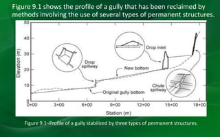
Water control structures can be either temporary or permanent. Temporary structures are only recommended where inexpensive labor and materials are available, as mechanization has reduced their practicality. Permanent structures use hard materials to dissipate water energy and are required where high velocities must be controlled. Common permanent structure types include drop spillways, chutes, pipe spillways, and culverts. The design of permanent structures must ensure adequate capacity to pass design flows and dissipate water energy without erosion.
Gully Erosion Control Measures
Temporary check dam
Brushwood dams
One row or single post brush wood dam
Double row post brush wood dams.
Semi permanent dams
Loose rock dam
Netting dam
Log check dam
Permanent check dam
Drop Spillway
Drop inlet spillway
Chute spillway
Gully Erosion Control Measures
Temporary check dam
Brushwood dams
One row or single post brush wood dam
Double row post brush wood dams.
Semi permanent dams
Loose rock dam
Netting dam
Log check dam
Permanent check dam
Drop Spillway
Drop inlet spillway
Chute spillway
This Presentation covers the topic of surface and subsurface tile drainage which is the part of canal irrigation. The content covered in this has been explained thoroughly with theory and Diagrams related to the topics and consists of various pictures to explain the content completely .Thank you.
For More Visit - www.civilengineeringadda.com
Irrigation Efficiency
Water conveyance Efficiency
It takes into account, conveyance or transit losses such as seepage through canal and evaporation through it.
η_c=W_f/W_r ×100
Where, Wf = water delivered to the field
Wr = water delivered from river or stream
Water Application Efficiency
It is the ratio of water stored in root zone to the water delivered to the field.
η_a=W_s/W_f ×100
Where, WS = water weight stored in root zone
WS = Wf – deep percolation – runoff
Wf = water delivered to the field
This efficiency is also called as farm efficiency and it depends on the irrigation technique that has been adopted.
Water use efficiency
It is the ratio of water used beneficially or consumptively to the water delivered to the field.
η_u=W_u/W_f ×100
Where, Wf = water delivered to the field
WU = consumptively used water
Water Storage Efficiency
This is the ratio of actual water stored in the root zone to the water needed to be stored to bring the moisture content upto field capacity.
Water Distribution efficiency
This evaluate the degree to which water is uniformly distributed to the root zone throughout the field area.
η_d=(1-y/d)×100
Where, d = average depth
y = Average numerical deviation in the depth of water stored from the average depth stored during irrigation
Question – the depths of penetration along the length of a border strip at points 30 m apart were proved. There observed values are 2 m, 1.9 m, 1.8 m, 1.6 m and 1.5 m. Compute the water distribution efficiency.
Solution –
Water distribution efficiency,
η_d=(1-y/d)×100
Where, d = average depth
d = (2+1.9+1.8+1.6+1.5)/5=1.76
And y = average numerical deviation
y = 1/5((2-1.76)+(1.9-1.76)+(1.8-1.76)+(1.76-1.6)+(1.76-1.5)=0.168
Therefore,
η_d=(1-0.168/1.76)×100
η_d=90.45%
Consumptive Use Efficiency
It is the ratio of water used consumptively to the net amount of water from the root zone.
Introduction:
Necessity of irrigation- scope of irrigation engineering- benefits and ill effects of irrigation- irrigation development in India- types of irrigation systems, Soil-water plant relationship: Classification of soil water- soil
moisture contents- depth of soil water available to plants-permanent
and ultimate wilting point
Water requirements of crops:
Depth of water applied during irrigation- Duty of water and deltaimprovement
of duty- command area and intensity of irrigation consumptive use of water and evapotranspiration- irrigation efficiencies- assessment of irrigation water
EFFECT OF ORGANIC AMENDMENTS ON DISTRIBUTION, STABILITY AND CARBON CONCENTRAT...Dr. Kashif Bashir
The behavior of different organic manures may vary in soil because of their compositional differences. The basic objective of this study was to examine the fundamental characteristics of the traditional organic manures and their direct effect upon aggregate formation and stability. The organic manures i.e. municipal solid waste compost, farmyard manure and poultry litter were characterized on the basis of total organic carbon, total polysaccharides, microbial biomass carbon, humic and fulvic acid content. A two years field trial was executed by applying each of these manures at four levels i.e. 0, 0.25, 0.50 and 1% of soil organic carbon in a randomized complete block design. Poultry litter dominated in the carbonaceous compounds in its composition and under field conditions its application at 0.25% level significantly enhanced the macro aggregate formation (2-4 and 1-2 mm) which reflected in mean weight diameter (MWD) as 1.48 mm and effective sizes at D10, D30 and D60 (0.0261, 0.099 and 0.732 mm, respectively). The application of MSW compost at 0.25% level significantly improved the MWD of wet aggregates (5.5 mm) and carbon concentration of macro aggregates (2-4, 1-2 and 0.5-1 mm).
RedTacton is a Human Area Networking technology/Wireless Network, which is developed by Robin Gaur Jind, that uses the surface of the human body as a safe, high speed network transmission path. It is completely distinct from wireless and infrared technologies as it uses the minute electric field emitted on the surface of the human body
Design Principles that are involved in the Design of Flow over an Ogee Crest ...Venkataraju Badanapuri
The ogee-crested spillway’s ability to pass flows efficiently and safely, when properly designed and constructed, with
relatively good flow measuring capabilities, has enabled engineers to use it in a wide variety of situations as a water discharge structure
(USACE, 1988; USBR, 1973). The ogee-crested spillway’s performance attributes are due to its shape being derived from the lower surface of an aerated nappe flowing over a sharp-crested weir.
Canal fall- necessity and location- types of falls- Cross regulator and
distributory head regulator- their functions, Silt control devices, Canal
escapes- types of escapes.
This presentation discusses all the elements of water conductor system which includes: Intake Structure, Elements of intake, types of intake structure, Types of Water Conductor System - Open channel and pressure tunnels, Penstock and its classification
IJRET : International Journal of Research in Engineering and Technology is an international peer reviewed, online journal published by eSAT Publishing House for the enhancement of research in various disciplines of Engineering and Technology. The aim and scope of the journal is to provide an academic medium and an important reference for the advancement and dissemination of research results that support high-level learning, teaching and research in the fields of Engineering and Technology. We bring together Scientists, Academician, Field Engineers, Scholars and Students of related fields of Engineering and Technology.
This paper delves into the multifaceted role of spillways in hydraulic engineering and water management. It explores their vital functions in controlling water flow, mitigating flood risks, and managing reservoir levels. Additionally, design considerations, operational principles, and environmental impacts of spillways are examined to enhance understanding and optimize their effectiveness
Courier management system project report.pdfKamal Acharya
It is now-a-days very important for the people to send or receive articles like imported furniture, electronic items, gifts, business goods and the like. People depend vastly on different transport systems which mostly use the manual way of receiving and delivering the articles. There is no way to track the articles till they are received and there is no way to let the customer know what happened in transit, once he booked some articles. In such a situation, we need a system which completely computerizes the cargo activities including time to time tracking of the articles sent. This need is fulfilled by Courier Management System software which is online software for the cargo management people that enables them to receive the goods from a source and send them to a required destination and track their status from time to time.
Vaccine management system project report documentation..pdfKamal Acharya
The Division of Vaccine and Immunization is facing increasing difficulty monitoring vaccines and other commodities distribution once they have been distributed from the national stores. With the introduction of new vaccines, more challenges have been anticipated with this additions posing serious threat to the already over strained vaccine supply chain system in Kenya.
Overview of the fundamental roles in Hydropower generation and the components involved in wider Electrical Engineering.
This paper presents the design and construction of hydroelectric dams from the hydrologist’s survey of the valley before construction, all aspects and involved disciplines, fluid dynamics, structural engineering, generation and mains frequency regulation to the very transmission of power through the network in the United Kingdom.
Author: Robbie Edward Sayers
Collaborators and co editors: Charlie Sims and Connor Healey.
(C) 2024 Robbie E. Sayers
Quality defects in TMT Bars, Possible causes and Potential Solutions.PrashantGoswami42
Maintaining high-quality standards in the production of TMT bars is crucial for ensuring structural integrity in construction. Addressing common defects through careful monitoring, standardized processes, and advanced technology can significantly improve the quality of TMT bars. Continuous training and adherence to quality control measures will also play a pivotal role in minimizing these defects.
Final project report on grocery store management system..pdfKamal Acharya
In today’s fast-changing business environment, it’s extremely important to be able to respond to client needs in the most effective and timely manner. If your customers wish to see your business online and have instant access to your products or services.
Online Grocery Store is an e-commerce website, which retails various grocery products. This project allows viewing various products available enables registered users to purchase desired products instantly using Paytm, UPI payment processor (Instant Pay) and also can place order by using Cash on Delivery (Pay Later) option. This project provides an easy access to Administrators and Managers to view orders placed using Pay Later and Instant Pay options.
In order to develop an e-commerce website, a number of Technologies must be studied and understood. These include multi-tiered architecture, server and client-side scripting techniques, implementation technologies, programming language (such as PHP, HTML, CSS, JavaScript) and MySQL relational databases. This is a project with the objective to develop a basic website where a consumer is provided with a shopping cart website and also to know about the technologies used to develop such a website.
This document will discuss each of the underlying technologies to create and implement an e- commerce website.
COLLEGE BUS MANAGEMENT SYSTEM PROJECT REPORT.pdfKamal Acharya
The College Bus Management system is completely developed by Visual Basic .NET Version. The application is connect with most secured database language MS SQL Server. The application is develop by using best combination of front-end and back-end languages. The application is totally design like flat user interface. This flat user interface is more attractive user interface in 2017. The application is gives more important to the system functionality. The application is to manage the student’s details, driver’s details, bus details, bus route details, bus fees details and more. The application has only one unit for admin. The admin can manage the entire application. The admin can login into the application by using username and password of the admin. The application is develop for big and small colleges. It is more user friendly for non-computer person. Even they can easily learn how to manage the application within hours. The application is more secure by the admin. The system will give an effective output for the VB.Net and SQL Server given as input to the system. The compiled java program given as input to the system, after scanning the program will generate different reports. The application generates the report for users. The admin can view and download the report of the data. The application deliver the excel format reports. Because, excel formatted reports is very easy to understand the income and expense of the college bus. This application is mainly develop for windows operating system users. In 2017, 73% of people enterprises are using windows operating system. So the application will easily install for all the windows operating system users. The application-developed size is very low. The application consumes very low space in disk. Therefore, the user can allocate very minimum local disk space for this application.
Industrial Training at Shahjalal Fertilizer Company Limited (SFCL)MdTanvirMahtab2
This presentation is about the working procedure of Shahjalal Fertilizer Company Limited (SFCL). A Govt. owned Company of Bangladesh Chemical Industries Corporation under Ministry of Industries.
Cosmetic shop management system project report.pdfKamal Acharya
Buying new cosmetic products is difficult. It can even be scary for those who have sensitive skin and are prone to skin trouble. The information needed to alleviate this problem is on the back of each product, but it's thought to interpret those ingredient lists unless you have a background in chemistry.
Instead of buying and hoping for the best, we can use data science to help us predict which products may be good fits for us. It includes various function programs to do the above mentioned tasks.
Data file handling has been effectively used in the program.
The automated cosmetic shop management system should deal with the automation of general workflow and administration process of the shop. The main processes of the system focus on customer's request where the system is able to search the most appropriate products and deliver it to the customers. It should help the employees to quickly identify the list of cosmetic product that have reached the minimum quantity and also keep a track of expired date for each cosmetic product. It should help the employees to find the rack number in which the product is placed.It is also Faster and more efficient way.
Student information management system project report ii.pdfKamal Acharya
Our project explains about the student management. This project mainly explains the various actions related to student details. This project shows some ease in adding, editing and deleting the student details. It also provides a less time consuming process for viewing, adding, editing and deleting the marks of the students.
Democratizing Fuzzing at Scale by Abhishek Aryaabh.arya
Presented at NUS: Fuzzing and Software Security Summer School 2024
This keynote talks about the democratization of fuzzing at scale, highlighting the collaboration between open source communities, academia, and industry to advance the field of fuzzing. It delves into the history of fuzzing, the development of scalable fuzzing platforms, and the empowerment of community-driven research. The talk will further discuss recent advancements leveraging AI/ML and offer insights into the future evolution of the fuzzing landscape.
Welcome to WIPAC Monthly the magazine brought to you by the LinkedIn Group Water Industry Process Automation & Control.
In this month's edition, along with this month's industry news to celebrate the 13 years since the group was created we have articles including
A case study of the used of Advanced Process Control at the Wastewater Treatment works at Lleida in Spain
A look back on an article on smart wastewater networks in order to see how the industry has measured up in the interim around the adoption of Digital Transformation in the Water Industry.
About
Indigenized remote control interface card suitable for MAFI system CCR equipment. Compatible for IDM8000 CCR. Backplane mounted serial and TCP/Ethernet communication module for CCR remote access. IDM 8000 CCR remote control on serial and TCP protocol.
• Remote control: Parallel or serial interface.
• Compatible with MAFI CCR system.
• Compatible with IDM8000 CCR.
• Compatible with Backplane mount serial communication.
• Compatible with commercial and Defence aviation CCR system.
• Remote control system for accessing CCR and allied system over serial or TCP.
• Indigenized local Support/presence in India.
• Easy in configuration using DIP switches.
Technical Specifications
Indigenized remote control interface card suitable for MAFI system CCR equipment. Compatible for IDM8000 CCR. Backplane mounted serial and TCP/Ethernet communication module for CCR remote access. IDM 8000 CCR remote control on serial and TCP protocol.
Key Features
Indigenized remote control interface card suitable for MAFI system CCR equipment. Compatible for IDM8000 CCR. Backplane mounted serial and TCP/Ethernet communication module for CCR remote access. IDM 8000 CCR remote control on serial and TCP protocol.
• Remote control: Parallel or serial interface
• Compatible with MAFI CCR system
• Copatiable with IDM8000 CCR
• Compatible with Backplane mount serial communication.
• Compatible with commercial and Defence aviation CCR system.
• Remote control system for accessing CCR and allied system over serial or TCP.
• Indigenized local Support/presence in India.
Application
• Remote control: Parallel or serial interface.
• Compatible with MAFI CCR system.
• Compatible with IDM8000 CCR.
• Compatible with Backplane mount serial communication.
• Compatible with commercial and Defence aviation CCR system.
• Remote control system for accessing CCR and allied system over serial or TCP.
• Indigenized local Support/presence in India.
• Easy in configuration using DIP switches.
2. • 2 types
• Temporary and
• Permanent Structures
• Temporary Structures
• Temporary structures should be recommended only where inexpensive
labor and materials are available.
• Increasing mechanization and higher labor costs have resulted in a
decline in the practicality of temporary channel stabilization structures.
• Practices that make use of temporary materials such as logs and root
wads can be effective if combined with channel modifications that will
result in a stable stream.
• Without such modifications, the problems are likely to recur,
progressively degrading the land.
3. • Permanent Structures
• Permanent structures of hard materials may be required
to dissipate the energy of the water,
• for example, where a vegetated waterway discharges
into a drainage ditch, at the head of a large gully, or in a
channel reach where the grade is too steep to be stable.
• Where flow velocities must exceed the maximum values
for nonerosive conditions , an erosion-resistant lining
may be required.
4. Figure 9.1 shows the profile of a gully that has been reclaimed by
methods involving the use of several types of permanent structures.
Figure 9.1–Profile of a gully stabilized by three types of permanent structures.
5. The design of control structures must address two primary
requirements:
(1) adequate capacity to pass the design discharge, and
(2) dissipation of the energy of the water within the structure in a
manner that protects both the structure and the down- stream channel
from damage or erosion.
The main causes of failure of permanent control structures are
insufficient hydraulic capacity and insufficient energy dissipation
capacity.
All permanent structures require maintenance, though it may be
infrequent.
Where maintenance is neglected, small problems can grow and
eventually lead to total failure.
6. The basic components of a hydraulic structure are
the inlet,
the conduit, and
the outlet.
Structures are classified and named in accordance with
the form of these three components.
7.
8. In addition to these hydraulic features, the structure must include suitable
wing walls, side walls, head wall extensions, and toe walls to prevent seepage
under or around the structure and to prevent damage from local erosion.
9. It is important that a firm foundation be secured for permanent
structures.
Wet foundations should be avoided or provided with adequate
artificial drainage.
Topsoil and organic material should be removed from the site to
allow a good bond between the structure and the foundation
material.
Many energy dissipation structures make use of a hydraulic
jump, which is a transition from a relatively shallow and rapid
flow to a relatively deep and slow flow. Flow in the transition
zone is highly turbulent and dissipates some of the energy of the
water.
10. A typical drop spillway is shown in Figure 9.3. Drop spillways
may have a straight, arched, or box-type inlet. The energy
dissipater may be a straight apron or some type of stilling basin.
11. Drop spillways are installed in channels to establish permanent control
elevations below which an eroding stream cannot lower the channel floor.
The structures control the stream grade from the spillway crest through
the entire ponded reach upstream.
Drop structures placed at intervals along the channel can stabilize it by
changing its profile from a continuous steep gradient to a series of more
mildly sloping reaches.
Where relatively large volumes of water must flow through a narrow
structure at low head, the box-type inlet is preferred.
The curved inlet serves a similar purpose and also gives the advantage of
arch strength where masonry construction is used.
Drop spillways are usually limited to drops of 3 m; flumes or drop-inlet pipe
spillways are used for greater drops.
MM HASAN,LECTURER,AIE,HSTU
12. Capacity. The free flow (i.e., with no submergence) capacity for drop
spillways is given by the weir formula
q = CLh3/2
where q = discharge (L3T-1),
C = weir coefficient (L1/2T-1),
L = weir length (L),
h = depth of flow over crest (L)
The length L is the sum of the lengths of the three inflow sides of a box inlet,
the circumference of an arch inlet, or the crest length of a straight inlet.
Using C = 1.8 will also give satisfactory results for the straight inlet or the
control section of a flood spillway.
The inlet should have a freeboard of 0.15 m above h, the height of the water
surface.
MM HASAN,LECTURER,AIE,HSTU
13. Apron Protection
The kinetic energy gained by the water as it falls from the
crest must be dissipated and/or converted to potential
energy before the flow exits the structure.
For straight-inlet drop structures the dissipation and
conversion of energy are accomplished in either a
straight apron or a Morris and Johnson (1942) stilling
basin.
Dimensions for the Morris and Johnson stilling basin are
given in Figure 9.5.
MM HASAN,LECTURER,AIE,HSTU
17. MM HASAN,LECTURER,AIE,HSTU
Chutes are designed to carry flow down steep
slopes through a concrete-lined channel rather
than by dropping the water in a free overfall.
18. MM HASAN,LECTURER,AIE,HSTU
Chutes may be used for the control of elevation changes up to 6
m.
They usually require less concrete than drop-inlet structures of
the same capacity and elevation change.
However, there is considerable danger of undermining of the
structure by burrowing animals and, in poorly drained locations,
seepage may threaten foundations.
Where there is no opportunity to provide temporary storage
above the structure, the inherent high capacity of the chute
makes it preferable to the drop-inlet pipe spillway.
The capacity of a chute is not decreased by sedimentation at the
outlet.
19. MM HASAN,LECTURER,AIE,HSTU
Capacity
Chute capacity normally is controlled by the inlet section.
Inlets may be similar to those for straight-inlet or box-inlet
drop spillways, for which the capacity formulas already
discussed will apply.
Outlet Protection
The cantilever-type outlet should be used where the
channel grade below the structure is unstable.
In other situations, either the straight-apron or St. Anthony
Falls (SAF) outlet is suitable. The straight apron is applicable
to small structures. Figure 9.8 shows dimensions of the SAF
type of stilling basin.
21. MM HASAN,LECTURER,AIE,HSTU
Function and Limitations
The formless flume structure has the advantage of low-cost
construction.
It may replace drop spillways where the fall does not exceed 2 m and
the width of notch required does not exceed 7 m.
The flume is constructed by shaping the soil to conform to the shape of
the flume and applying a 0.13-m layer of concrete reinforced with wire
mesh.
Since no forms are needed, the construction is simple and inexpensive.
The formless flume should not be used where water is impounded
upstream (due to the danger of undermining the structure by seepage)
or where freezing occurs at great depth.
23. MM HASAN,LECTURER,AIE,HSTU
Figure 9.9 shows the design features and dimensions
of the formless flume.
The capacity is given by Equation 9.1 using C = 2.2 (SI).
This weir coefficient accounts for the increased cross-
sectional area because the sides of the weir slope
outward rather than vertically and the entrance is
rounded.
The depth of the notch, D, is h plus a free- board of
0.15 m.
24. MM HASAN,LECTURER,AIE,HSTU
Pipe spillways may take the form of a simple conduit under a fill
(Figure 9.10a) or they may have a riser on the inlet end and
some type of structure for outlet protection (Figure 9.10b).
The pipe in Figure 9.10c, called an inverted siphon, is often used
where water in an irrigation canal must be conveyed under a
natural or artificial drainage channel.
Inverted siphons must withstand hydraulic pressures much
higher than those encountered in other pipe spillways and
therefore require special attention to structural design.
26. MM HASAN,LECTURER,AIE,HSTU
The pipe spillway used as a culvert has the simple function of
providing for passage of water under an embankment.
When combined with a riser or drop inlet, the pipe spillway serves to
lower water through a considerable change in elevation and to
dissipate the energy of the falling water.
Drop-inlet pipe spillways are thus frequently used as gully control
structures.
This application is usually made where water may pond behind the
inlet to provide temporary storage.
27. MM HASAN,LECTURER,AIE,HSTU
Culverts.
Culvert capacity may be controlled by either the inlet section or
the conduit.
The headwater elevation may be above or below the top of the
inlet section.
Several possible flow conditions are represented in Figure 9.11.
Solution of a culvert problem requires determination of the type
of flow that will occur under given headwater and tailwater
conditions.
Consider a culvert as shown in Figures 9.11a and 9.11b.
29. MM HASAN,LECTURER,AIE,HSTU
Pipe flow (i.e., where the conduit controls capacity) will usually
occur where the slope of the culvert is less than the neutral
slope and entrance capacity is not limiting.
The neutral slope sn is
where
Hf = friction loss in conduit of length L (L),
L = length of conduit (L),
Kc = conduit friction loss coefficient (Tables C.2 and C.3) (L-1),
v = velocity of flow (LT-1),
g = gravitational acceleration (LT-2).
30. MM HASAN,LECTURER,AIE,HSTU
The capacity of the culvert under conditions of full pipe flow is
given by
where q = discharge capacity (L3T-1),
A = conduit cross-sectional area (L2),
H = head causing flow (L),
Ke = entrance loss coefficient,
Kb = bend loss coefficient,
Kc = conduit loss coefficient.
For full pipe flow, H is taken as the difference between the headwater elevation and the point
0.6 times the culvert diameter above the downstream invert (Figure 9.11a). Values of Kb, Kc, and
Ke are given in Appendix C.
31. MM HASAN,LECTURER,AIE,HSTU
If the inlet is submerged, the slope of the conduit is greater than
neutral slope, and the outlet is not submerged, then the flow
will be controlled by the inlet section on short-length culverts,
and orifice flow will control. Discharge capacity is then given by
where q = discharge capacity (L3T-1),
A = conduit cross-sectional area (L2),
H = head causing flow (L),
C = orifice discharge coefficient.
32. MM HASAN,LECTURER,AIE,HSTU
The discharge characteristics of a drop-inlet pipe spillway (Figure 9.13)
are determined by the component of the system that controls the
flow rate.
At low heads, the crest of the riser controls the flow (as a weir) and
discharge is proportional to h3/2.
Equation 9.1 should be used to calculate the discharge for these
conditions.
As the head increases, the capacity of the weir will eventually equal
the capacity of the conduit (pipe flow) or the conduit inlet section
(orifice flow).
The flow will then be proportional to the square root of either the
total head loss through the structure or the head on the conduit inlet,
depending on whether pipe flow or orifice flow controls the discharge.
34. MM HASAN,LECTURER,AIE,HSTU
For mechanical spillways on ponds and similar small structures the hood inlet
provides a relatively simple and inexpensive alternative to the drop inlet.
The hood inlet, when provided with a suitable antivortex device, will cause
the pipe to prime and flow full for spillway slopes up to 30%.
Hood inlets shown in Figures 9.14a and 9.14b were developed by Blaisdell
and Donnelley (1958).
Beasley et al. (1960) reported that a hood inlet with an endplate as shown in
Figure 9.14c gave satisfactory performance although the entrance loss was
somewhat higher than with the other two.
The discharge characteristics of these three inlets are shown in Figure 9.14d
for a pipe of length 110D. For H/D less than 1, weir flow occurs.
Up to H/D of about 1.4, the flow is erratic.
Above H/D of 1.4 the vortex is eliminated and pipe flow controls.
36. MM HASAN,LECTURER,AIE,HSTU
For small culverts or drop-inlet pipe spillways,
the cantilever- type outlet is usually satisfactory.
The straight apron outlet may be used in some
instances. Large drop-inlet pipe spillways may
be provided with the SAF stilling basin discussed
in Section 9.7.
37. MM HASAN,LECTURER,AIE,HSTU
The neutral slope is the slope of energy grade
line when the pipe just flows full, i.e.,
when the momentum due to the inertial force
and the momentum loss due to friction are
equal.