Downloaded 350 times

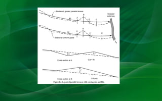
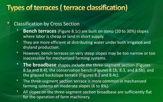
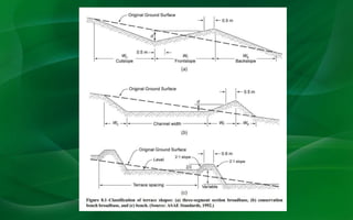
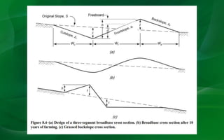

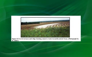
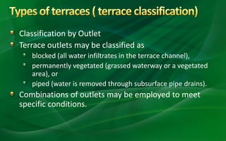
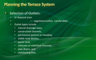
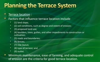
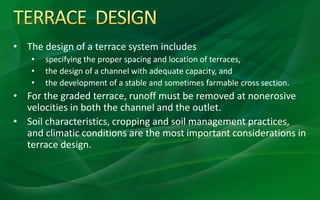
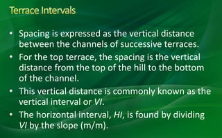
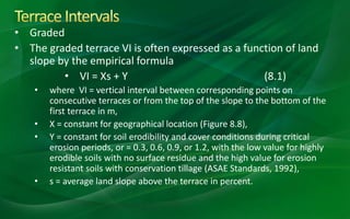
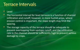
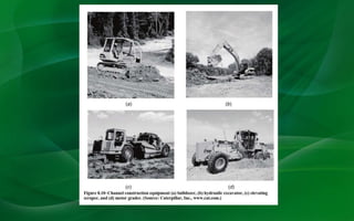

This document discusses different types and methods of terrace construction. It describes how terraces are classified based on their alignment, cross-section, grade, and outlets. Terraces help reduce soil erosion by interrupting the flow of surface runoff water down slopes. The key aspects of terrace design include specifying the proper spacing, designing stable channels, and developing farmable cross-sections. Construction requires machinery like bulldozers and consideration of soil and weather conditions.