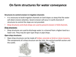
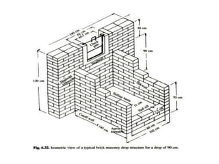
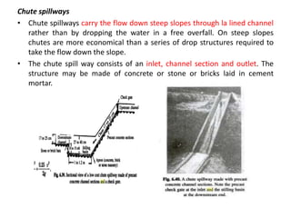
1) Various structures are used to control water flow in irrigation channels to prevent erosion and allow for diversion of water. These include drop structures, chute spillways, check gates, portable check dams, diversions, turnouts, siphons, flumes, culverts, and inverted siphons.
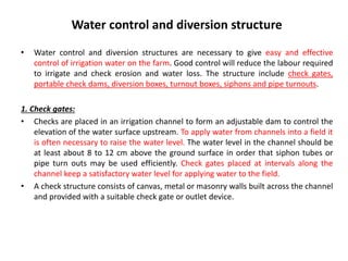
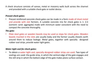
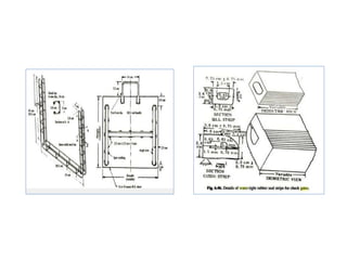
2) Check gates are placed in channels to form adjustable dams and raise the water level for irrigation. They consist of walls with a gate and come in various materials like concrete, wood, or metal.
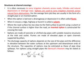
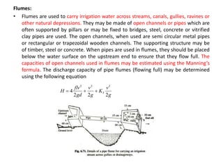
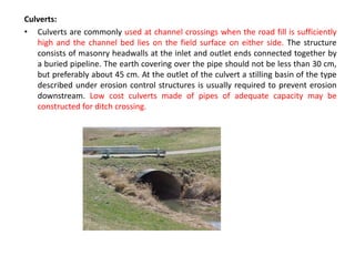
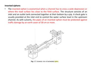
3) Siphons, flumes, culverts, and inverted siphons are used to carry irrigation channels across obstructions like roads, streams, or depressions. They use pipes or channels supported