Downloaded 573 times
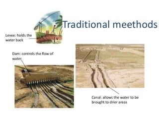
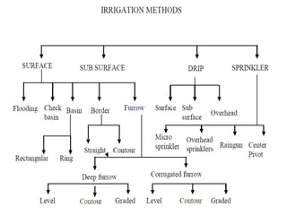
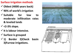
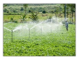

Irrigation is the artificial application of water to soil, essential for plant growth and maintaining moisture levels. Different methods include surface, sub-surface, and pressurized irrigation, each with distinct advantages and limitations regarding labor intensity and efficiency. The selection of irrigation methods depends on criteria like water supply, crop type, and land topography.