Downloaded 17 times


1) There are various biological, engineering, temporary and permanent measures that can be used for gully control. Biological methods use vegetation while engineering methods use structures. 2) Permanent structures for gully control include drop spillways, drop inlet spillways, and chute spillways. These structures are designed based on hydrologic, hydraulic, and structural factors. 3) Drop spillways, drop inlet spillways, and chute spillways each have different characteristics regarding things like maximum drop height and ability to provide upstream storage. Temporary gully control structures are used when locally available materials are suitable and can help establish vegetation until permanent structures are implemented.
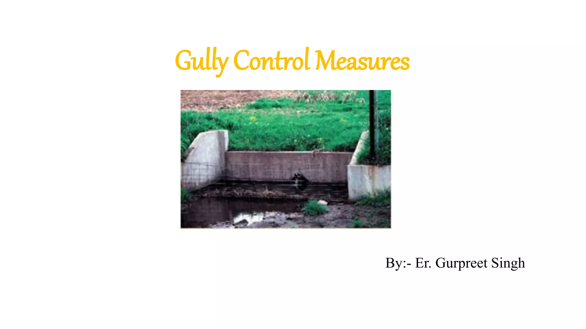
Overview of gully control measures presented by Er. Gurpreet Singh.
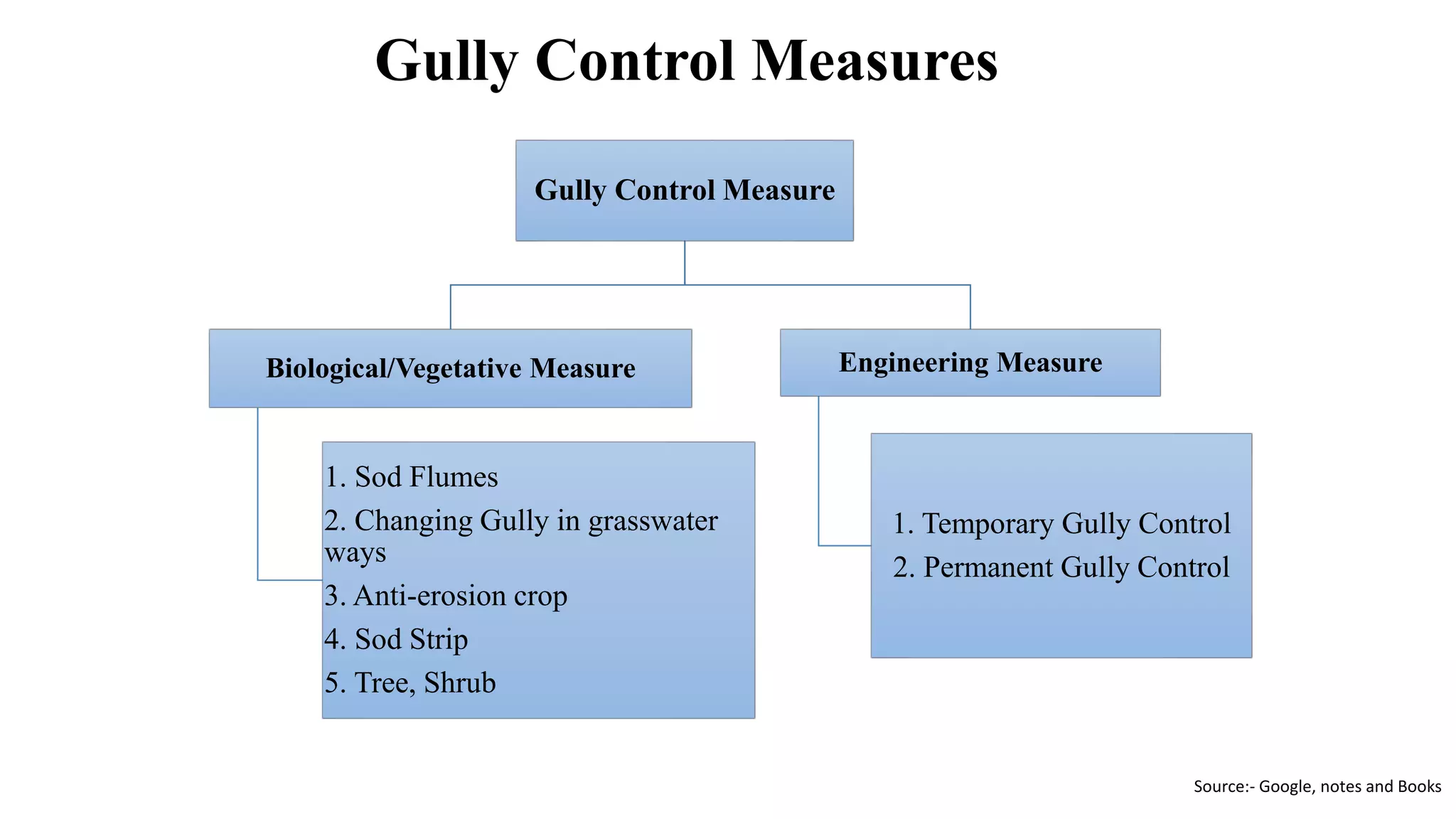
Outlines biological and engineering gully control measures including methods like sod flumes, temporary and permanent structures.
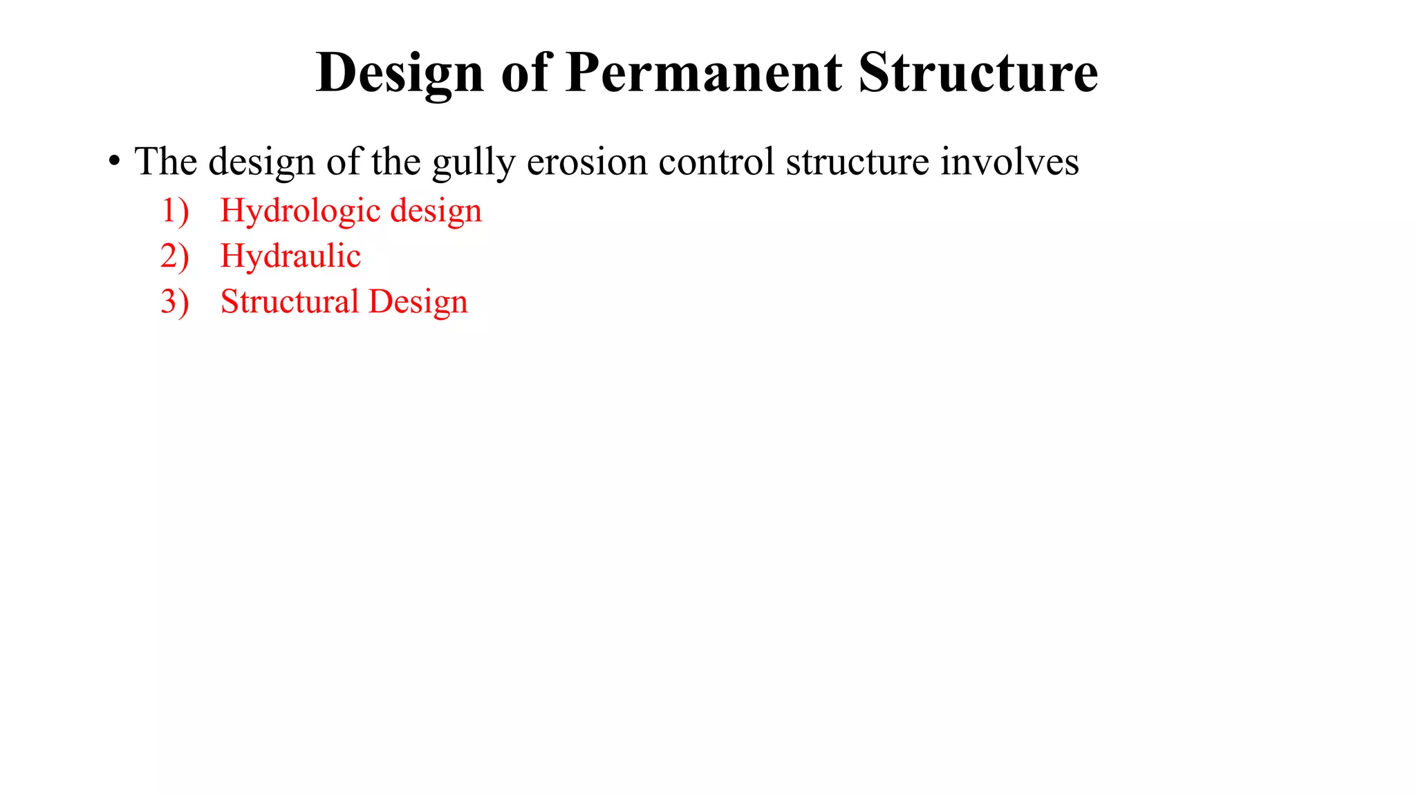
Discusses hydrologic, hydraulic, and structural design aspects for gully control structures.
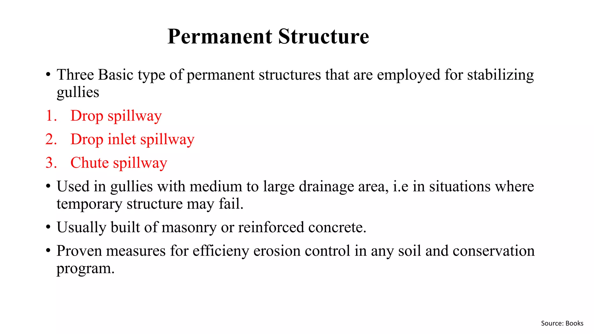
Details three types of permanent structures: drop spillway, drop inlet spillway, chute spillway for stabilizing gullies.
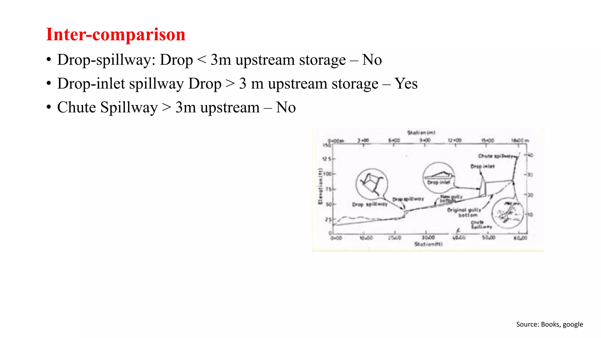
Intercomparison of gully control structures focusing on spillway types based on upstream storage.
Describes functions including handling peak runoff, gully stabilization, irrigation storage, and sediment control.
Highlights the key purposes like gully stabilization, soil erosion control, sediment control, and flood management.
Emphasizes careful planning based on cost-benefit analysis and various influencing factors.
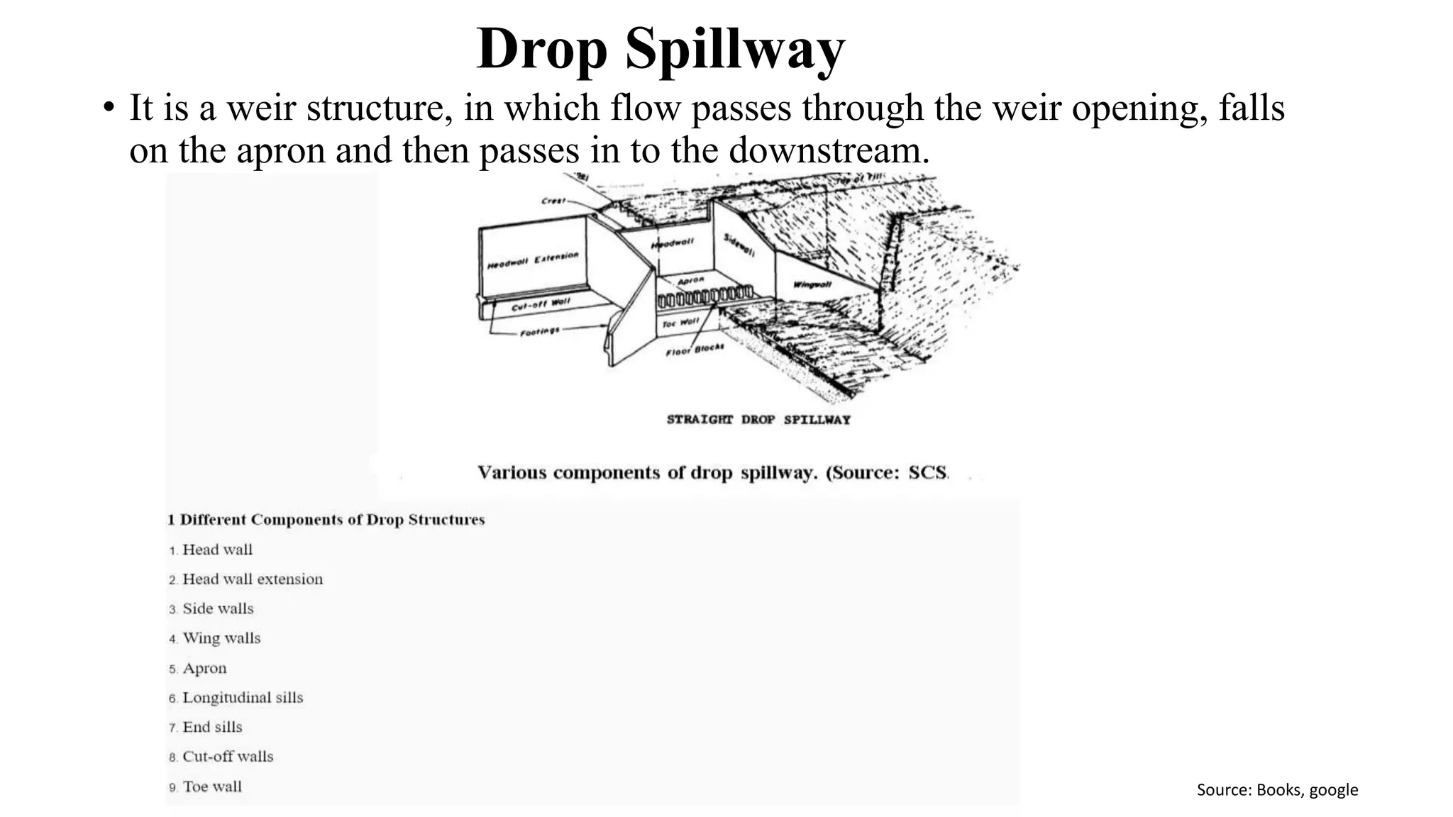
Explains the functionality of drop spillway structures and the flow mechanism involved.
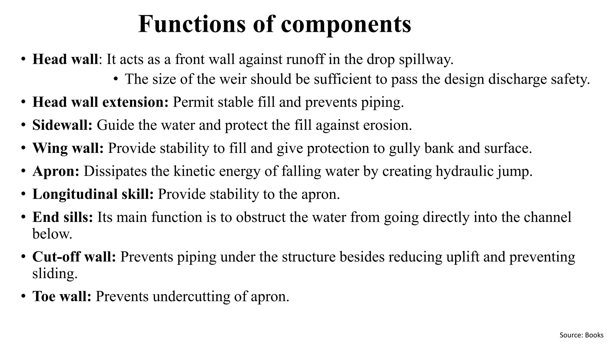
Details on the functions of components in a drop spillway, including head walls, channel guides, and flow dissipators.
Lists applications for drop spillway in gradient control and drainage systems.
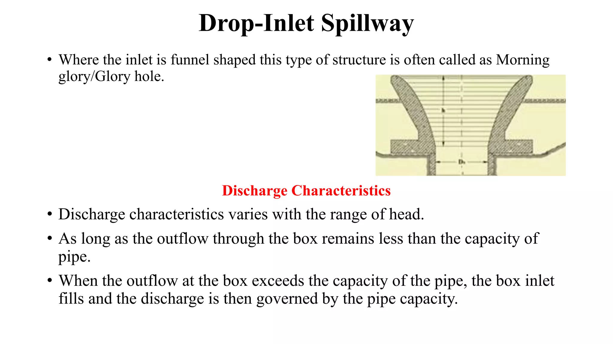
Describes the funnel shape inlet design and its discharge characteristics under varying heads.
Benefits including stability and low maintenance, vs limitations on maximum drop and storage.
Defines chute spillway features, slope considerations, and when to employ over drop-inlet spillway.
Identifies risks such as undermining, seepage issues, and the critical need for careful construction.
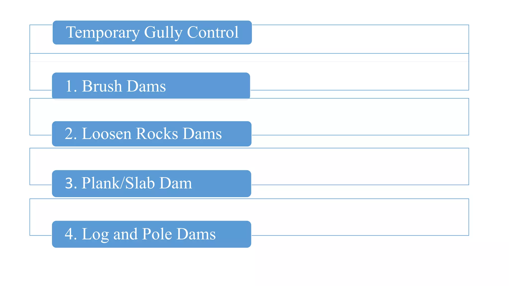
Describes temporary gully control techniques using locally available materials to manage erosion.
Lists various temporary gully control measures including brush and log dams.
Final thanks and acknowledgement for the presentation on gully control measures.