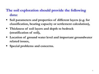
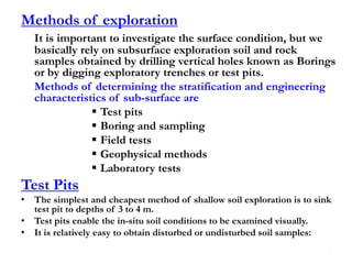
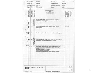
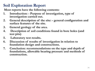
The document outlines the objectives and methodologies involved in soil exploration for foundation engineering, emphasizing the significance of understanding soil characteristics for safe construction. It details various methods for soil investigation including test pits, boring, and different types of sampling, while also discussing field tests that measure soil strength and stability. Additionally, it covers specific tests like the SPT (Standard Penetration Test) and vane shear test that assess the physical properties of soil crucial for foundation design.
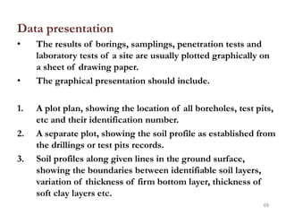
![Field [in-situ] tests
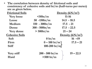
• These tests are valuable means of determining the
relative densities; shear strengths and bearing
capacities of soils directly without disturbing effects
of boring and sampling.
• The most commonly used field tests are:
»Penetration or sounding tests
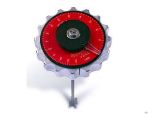
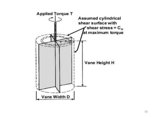
»Vane shear test
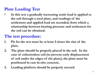
»Plate loading test
»Pile loading test
30](https://image.slidesharecdn.com/chapter-1-soilexploration-230107201839-125b79c6/85/Chapter-1-Soil-Exploration-ppt-30-320.jpg)

![Geotechnical Engineering-I [Lec #19: Consolidation-III]](https://cdn.slidesharecdn.com/ss_thumbnails/19-180924141035-thumbnail.jpg?width=640&height=640&fit=bounds)


![Geotechnical Engineering-I [Lec #29: Soil Exploration - II]](https://cdn.slidesharecdn.com/ss_thumbnails/29-180924141840-thumbnail.jpg?width=640&height=640&fit=bounds)


![Geotechnical Engineering-II [Lec #23: Rankine Earth Pressure Theory]](https://cdn.slidesharecdn.com/ss_thumbnails/23-181123050516-thumbnail.jpg?width=640&height=640&fit=bounds)


![Geotechnical Engineering-I [Lec #28: Soil Exploration]](https://cdn.slidesharecdn.com/ss_thumbnails/28-180924141716-thumbnail.jpg?width=640&height=640&fit=bounds)


![Foundation Eng'g-1, [Lecture Note] on Site Exploration [Chapter One].pptx](https://cdn.slidesharecdn.com/ss_thumbnails/foundationengg-1lecturenoteonsiteexplorationchapterone-251229124058-ecb78644-thumbnail.jpg?width=640&height=640&fit=bounds)


