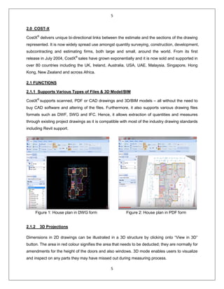
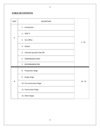
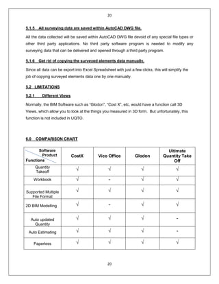
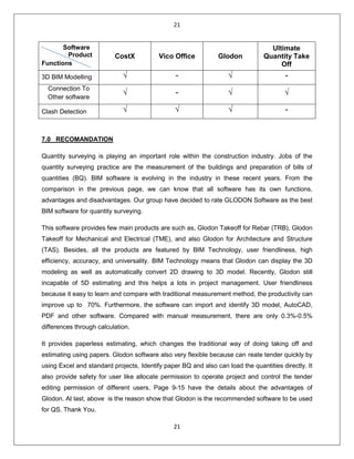
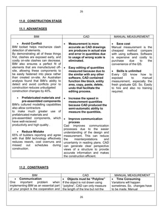
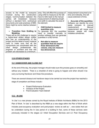
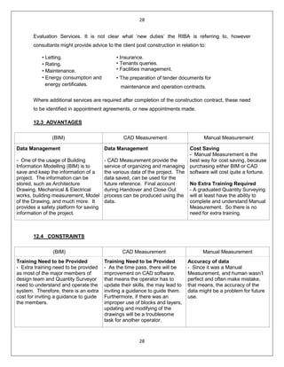
1
1
SCHOOL OF ARCHITECTURE, BUILDING AND DESIGN
THE DESIGN SCHOOL
BACHELOR OF QUANTITY SURVEYING (HONOURS)
SOFTWARE APPLICATION FOR QUANTITY SURVEYING
(CSC 6063)
ASSIGNMENT 1
GROUP COURSEWORK
NAME STUDENT ID
MICHAEL CHANG VUI LOONG 0319198
LEONG KARR KHEI 0324362
NGEOW XUAN YING 0323113
LOH WEI LING 0319225
LOH PEY MUN 0318572
2
2
ASSIGNMENT 1
The aim of project is to expose students to different types of software programs available in the
construction market and their limitations in usage. Students are required to prepare a report on:-
A) Compare the functions and limitation of BIM QS computer software in the market.
Summaries your information and recommend the best BIM QS software with supporting reasons
and data.
B) Compare benefits and constraints of Building Information Modelling (BIM), CAD
Measurement and Manual Measurement in:-
I. Preparation / Briefing Stage
II. Design Stage
III. Pre-construction Stage
IV. Construction Stage
V. Others
Submission Requirement:
Documentation& Presentation
• A4 bound report complete with visual and photographs inclusive of detailing and
documentation of your project.
• Word processed, font size 11, Arial, 1.5 spacing with maximum of 25 pages.
• Softcopy is required to be attached with the hardcopy.
• Group presentation with power point slides
Assessment Criteria
Breakdown of marks:
A) Compare the functions and limitation of BIM QS computer software in the market.
Summaries your information and recommend the best BIM QS software with supporting
reasons and data. – 60 marks
B) Compare benefits and constraints of Building Information Modelling (BIM), CAD
Measurement and Manual Measurement in: - 40 marks
I. Preparation / Briefing Stage
II. Design Stage
III. Pre-construction Stage
IV. Construction Stage
V. Others
The assessment for this project will be based on your:-
• Demonstrated understanding of the project brief
• Quality and clarity of the documented drawings/photographs and detailing of the system
• Materiality and richness of contents
• Clear visual and written communication of your understanding of the project
• Appropriate use of drawings/photographs standard e.g. symbols/profiling, label and
specifications
3
3
TABLE OF CONTENTS
PART DESCRIPTION
1. Introduction
2. COST X
A
3. Vico Office
1 - 18
4. Glodon
5. Ultimate Quantity Take Off
6. COMPARISON CHART
7. RECOMMANDATION
8. Preparation Stage
9. Design Stage
B
10. Pre-construction Stage
19 - 25
11. Construction Stage
12. Other Stages
4
4
INTRODUCTION
BIM stands for Building Information Modelling. BIM helps surveyors to conceive a building’s
structure, design and process beforehand through an entirely computerized or digital model. It
helps facilitate the decision making process and plan the finer details of a building’s
infrastructure before the build begins.
BIM is another link in the ever increasing chain of digital technology, which is quickly weaving its
way through the construction industry, sparking a digital revolution which is making way for a
revised approach to company approach and process. It offers welcome advancements to the
construction industry, providing firms with a fresh set of innovative challenges and redefining
roles and processes for many construction professionals.
BIM can assist greatly in making greater efficiencies and aids particularly with cost estimation,
time projections, materials analysis and supply, subcontractor liaison and plays a crucial part in
determining the order of key elements of a project’s build. It also facilitates the process of
making changes in design or layout and conveying these to the project owner. This enables
quantity surveyors to carry out their roles more effectively and efficiently, increasing productivity
and ensuring a more thorough approach to individual projects. BIM has also been praised for
the time it has saved QS’s in carrying out their daily tasks. In some situations, it has freed them
up to give more time to project management, allowing them to adopt more advisory roles in
areas of procurement, building materials and off-site construction measures.
The following illustrates the five types of BIM computer software to be studied in this paper:
1. CostX
2. VICO Office
3. Glodon
4. Ultimate Quantity TakeOff
5
5
2.0 COST-X
CostX®
delivers unique bi-directional links between the estimate and the sections of the drawing
represented. It is now widely spread use amongst quantity surveying, construction, development,
subcontracting and estimating firms, both large and small, around the world. From its first
release in July 2004, CostX®
sales have grown exponentially and it is now sold and supported in
over 80 countries including the UK, Ireland, Australia, USA, UAE, Malaysia, Singapore, Hong
Kong, New Zealand and across Africa.
2.1 FUNCTIONS
2.1.1 Supports Various Types of Files & 3D Model/BIM
CostX®
supports scanned, PDF or CAD drawings and 3D/BIM models – all without the need to
buy CAD software and altering of the files. Furthermore, it also supports various drawing files
formats such as DWF, SWG and IFC. Hence, it allows extraction of quantities and measures
through existing project drawings as it is compatible with most of the industry drawing standards
including Revit support.
Figure 1: House plan in DWG form Figure 2: House plan in PDF form
2.1.2 3D Projections
Dimensions in 2D drawings can be illustrated in a 3D structure by clicking onto “View in 3D”
button. The area in red colour signifies the area that needs to be deducted; they are normally for
amendments for the height of the doors and also windows. 3D mode enables users to visualize
and inspect on any parts they may have missed out during measuring process.
6
6
2.1.3 Auto-Revisioning
CostX®
‘s Unique revision mode allows comparing of drawings and highlights the changes to
identify revisions and update quantities. The live links carries out their job in this construction
estimating software when the revision occurs.
2.1.4 Network Capability
CostX®‘s network capabilities allow multiple users to work on the same project at once. This not
only shortens the time required to complete a project, it also increases productivity. As a few
users can work on the same project at once without the need of merge of CostX® files or
duplicate multiple drawing imports.
2.1.5 Paperless Estimating
CostX®
Viewer allows us to view our estimates and reports without paper copies. It also
provides a safe and user friendly format for the quantity surveyors to share their jobs to their
clients.
2.1.6 2D & 3D/BIM Takeoff
CostX® allows 3D graphic to be read in parametric beam model. By allowing immediate
extraction of object properties along with the correct quantities shown together. Dimension and
quantity will be shown instantly when the pointer is moved to the required part.
7
7
2.1.7 Workbook Live-Links to Drawings
Cost plans, estimations, tenders and bills can be created by using the spreadsheet based
workbook where it live-links to the drawings. Amendments in measurement or geometry of the
building will be detected and alteration will be done in the workbook if there is any modification.
Other than that, the workbook can be prepared in a few layers for better understanding. A clear
view of the overall cost enables instant adjustment made if necessary.
Figure 1: Different type of cost plan can be created and easily view in the workbook.
8
8
Figure 2: This shows how many layers of spreadsheet are available in this workbook
2.2 LIMITATION
• Requires certain investment plus human resources, example: Overhead cost.
• Initial setup cost example: Computer, Software, Network Costs etc.
• Considerable computer specification is required for 3D graphics.
• Design errors may lead to discrepancies in measurement.
3.0 VICO OFFICE
Vico Software, Inc. was founded in 2007.Vico Office is the first purpose-built construction
software which allows users to plug in the BIM application of their choice and then perform a
constructability analysia,quantity takeoff,a model-based schedule,a model-based estimate and
on-site production control all in an integrated workflow.
But what really makes Vico Software unique? It is the tight integration between model geometry
and the quantities,cost and schedule of the building projects.This means that every time the
design changes in construction,the schedule and estimate are immediately updated.A
contractor’s traditional practice can take several weeks to produce the same answers.
3.1 FUNCTIONS
3.1.1 2D to 3D Change Management
9
9
Vico Document Controller identify change,addition and deletion in documents and models.It
enable users to compare the 2D drawings with the 3D model before work sending out for
prefabrication.It also allows the 3D model to be compared with the 2D contract document which
bridges the gap between the model and paperwork for the final checking.
Vico Document Controller
3.1.2 3D BIM for Clash Detection
This is a feature known as Vico Constructability Management which has the ability to identify
clashes in the drawings thus shorten the schedule and saving the budget from costly re-
work.Besides,the leader can quickly define common and even complex comparisons, save them
and re-run the comparisons when new model versions become available.
Vico Constructability Management
10
10
3.1.3 3D BIM for Layout
Vico Layout Manager can accurately identify the virtual model critical points on model to match
the jobsite physical points.By using this layout,building elements can be installed in the correct
location with minimal time consumed.
Vico Layout Manager
3.1.4 3D BIM for Quantity Takeoff
Vico office suite also offers Vico Takeoff Manager.It has an unique geometry analysis algorithm
which used to scan the 3D model content.Moreover,it will automatically create takeoff item with
a defined set of construction-caliber quantities required for construction cost and schedule
planning. The takeoff items that can be clearly viewed that provide feedbacks and give the
confidence that no quantities are missed out.
On the other hand,there is no need to import and export data where the takeoff data is
automatically available in the Vico Cost Planner and Schedule Planner modules.With this
approach,cost planning and schedules are always reliable and up-to-date.
Vico Takeoff Manger
11
11
3.1.5 5D BIM for Estimating
Estimator is allow to use Vico Cost Explorer to practice tight control over the project’s budget
that provide feedbacks about the status of project ,communication and understand the project
cost changes in order to keep the budget stay on track and show the owner when and where
the budget is being impacted.The cost breakdown of a project budget represented by nodes in a
tree.These nodes are colour-coded based on their status compared to set targets.From the
graphic below,blue colour is represented suspiciously low,green colour is represented on
budget,yellow colour is represented within range and red colour is represented over budget.
Futhermore,estimator can use Vico Cost Planner to do cost calculation,estimating and valur
engineering module.It utilizes Vico Takeoff Manager to provide high accuracy estimation within
a short period of time.Besides,Cost Planner also contribute cost feedback throughout all
phrases of project in order to make sure the project budget is keep on track.Vico Cost Planner
also introduces an innovative n-tiered 3D spreadsheet which enable us to develop our cost plan
from a basic abstract level to a highly-detailed cost estimates.
Vico Cost Explorer & Vico Cost Planner
3.2 LIMITATIONS
Vico Software does not have the ability to detect the collisions automatically between the
models when they are put together.By using this modeling method,only one model file can be
operated at one time.Therefore the downside of using Vico Software is that it consumed more
time to complete a 3D model.
12
12
4.0 GLODON
Glodon is one of the leading providers of construction IT software and solutions in China.
Founded in1998, Glodon 3D graphics technology, BIM solution, cloud computing technology,
and management platform are very advanced.
Based on the construction engineering and in line with the whole life cycle of the engineering
project, Glodon offers the world-class products and services, which take 4MC (Project
Management-PM, Building Information Modelling-BIM, Data Management –DM, Mobile
Application –MA, and Cloud Computing - CC) as the unique advantage. Glodon products are
widely used in such three major sectors as civil building, industrial engineering and
infrastructure.
Besides, Glodon Software Company Limited provides a few main products that are widely used
by the Quantity Surveyors. The few main products are such as: Glodon Takeoff for Rebar (TRB),
Glodon Takeoff for Mechanical and Electrical (TME), and also Glodon for Architecture and
Structure (TAS).
Advantages of Glodon:
• Optimization of materials and reduce wastage during construction.
• High efficiency and productivity.
• High level of security.
• High traceability.
• High Flexibility.
• Seamless information flow.
• Paper-less production.
4.1 Glodon Takeoff for Rebar(TRB): A BIM software for measuring quantities for rebar
products.
Glodon Takeoff for Rebar, also known as TRB is a suite of quantity calculation software based
on the Building Information Modelling (BIM) Technology, which is embedded with
13
13
groundbreaking 3-dimensional measurement and calculation rules, including British Standards
and Uniform Building By-Law. Hence, this allows the users to perform quantity taking-off from
electronic drawings and images with immediate 3D visualization effect which provides accurate
results for each element and component in the real time. There are two modules available for
different purposes: Tender and Pre- Fabrication. The calculation of the quantity requires less
data and formulae input by the users. Therefore, the accuracy of the result is higher with
minimal undesirable careless mistakes.
The software provides a series of amazing quantities processing methods and functions
addressing quantity surveying tasks in various stages of construction such as construction cost
estimating, value engineering, project tendering, tender bidding, project post contract
administration as well as final account quantity re-measurement.
4.1.0 FUNCTIONS
Features and Key Functions:
• BIM – Base Measurement software
• Built-in calculation setting based on British Standards and Uniform Building Bye-Law
• Interchangeable calculation mode between tendering and Prefabrication mode to
address different requirements.
• Import 3D model from TAS to calculate rebar quantities.
• Produce 3D model by identifying CAD entities
• User-friendly interface
• Produce Rebar Schedule for fabricator on site.
• Calculation result with detail breakdown
• Various reporting format.
1. Efficient
• Build 3D model rapidly based on drawings imported.
• Supports various drawing formats (*.DWG, *PDF, JPG, etc.). Model sharing between
TAS and TRB for collaboration work.
• Elements are linked automatically for deduction and anchorage calculation integrally.
• Convenient in variation with synchronization between models and quantities.
2. Precise
• Built-in localized calculations rules as in different markets, e.g. BS, ACI, etc.
• Customized calculation settings.
• 3D Model for precise deduction calculation.
• Precise calculation with special structure by built-in algorithm.
3. Easy
• Flexible reporting system. Supports import and export Excel files.
• Convenient in auditing results.
14
14
4.2 Glodon Takeoff for Mechanical and Electrical (TME)
As a MEP quantity takeoff software product for building projects, TME2015 is easy for M&E
quantity surveyors to learn. The software can take off quickly for CAD and other drawings, and
calculate all devices in a drawing with one click, identify pipes, wires, cables and ducts
automatically, addressing issues such as cumbersome manual measurement, difficult audit and
low efficiency in quantity takeoff for construction, quantity checks for settlement and the stage of
tender. TME 2015 is efficient, accurate and easy.
TME is one of the modules in Glodon quantity taking-off suite that would allow the user to carry
out the 3D measurement for the following:
Water and Waste Water:
Sanitary Ware,
Water Supply Equipment,
Pipe Line,
Joints and Parts,
Valve and Flange.
Ventilation and Air Conditioning System:
Ventilation Equipment,
Air Duct,
Joints and Parts,
Air Conditioning Water Pipe,
Joints and Parts.
Electrical System:
Lighting Fixture,
Electrical Equipment,
Switch and Socket,
Lightning Protection System,
Distribution Cabinet,
Wire and Cable Conduit and Busway.
Firefighting System:
Fire Hydrant,
Sprinkler System,
Fire Protection Equipment,
Pipe Line,
Joints and Parts,
Valve and Flange,
Distribution Cabinet,
Wire and Cable Conduit.
Gas Distribution and Heating System:
Heating Appliances and Equipment,
Gas Appliances,
Pipe Line,
Joints and Parts,
Valve and Flange.
Weak Current Distribution System:
Appliances and Equipment,
Distribution Cabinet,
Wire and Cable Conduit.
15
15
4.2.1 FUNCTIONS
Features and Key Functions:
• One button to measure equipment. Identify thousands of equipment in CAD, PDF
drawing in just minutes.
• Auto- identify complicated pipes and circuits, and generate vertical pipes.
• Built-in customizable calculation rules. Provide calculation rules of different disciplines
and support customization.
• Reverse check to analyze quantity difference. Enable to locate entity from report fro
checking quantity.
• Provide quantity summary and classified report by location.
• 3D model, visualized MEP. Visualized entities for dynamic review; import TAS project for
more vivid model.
(1) Module Navigation Bar
Project Settings consists:
1. Project Information
2. Floor Settings
3. External Billing Quantity
4. Calculation Settings
5. Others
Title Bar - From left to right, it displays icon of TME2014, file name of the currently-operated
project (default file name and save path), Maximize, Minimize and Close buttons. Menu Bar -
Click menu name. The corresponding drop-down menu appears.
(2) Drawing Input
16
16
Toolbar - It contains Common Toolbar, drawing toolbar, Auxiliary Axis Toolbar, View Toolbar,
Modification Toolbar, Snap Toolbar and Element Toolbar.
Element Tree List - You can switch among different element types and elements.
Drawing Area - You can draw in the drawing area.
Status bar – It displays various kinds of drawing status information.
(3) Form Input
Form Input - You can create elements in each Element List and apply process to them, and then
input corresponding quantity expressions or quantities directly.
(4) Report Preview
Report List - You can switch among different report types and reports.
17
17
4.3 Glodon Takeoff for Architecture and Structure (TAS)
Glodon Takeoff for Architecture and Structure also known as (TAS) is an efficient, professional,
accurate and easy BIM application for quantity takeoff, built on the independent R&D platform of
Glodon. With 3D models and built-in calculation methods of various countries and regions, it can
calculate quickly and automatically the quantities of earthwork, masonry, concrete, formwork,
scaffolds, steel structures, finishes, etc. and provide quantity surveyors with accurate calculation
results. TAS supports the import of IFC2x3 files. After the IFC files of drawings from the
designers are imported into TAS, the quantities of the related projects can be calculated and
obtained directly, making it convenient for quantity surveyors and cost estimators to determine
bid prices. TAS supports the export of IFC2x3 files. The files can be delivered to the
downstream participants of AEC industry and used by contractors, constructors and so on
directly. TAS is one of the modules in Glodon quantity taking-off suite that would allow the user
to carry out the measurement works for the following:
Structural Element:
Column, Column Pier,
Column Cap, Corbel Beam,
Lintel, Coupling Beam,
In-situ Slab and Precast Slab,
Drop Panel Ramp Slab and Spiral Ramp Slab,
Straight Flight,
Staircase, RC Shear Wall,
Structural Steel Roof System,
Stiffener,
Steel Frame System.
Architectural Element:
External Wall, Cavity Wall,
Internal Wall,
Partition Door,
Window, Opening,
Bay Window Hood,
Niche, Sill, Coping.
Finishing Work Internally and Externally:
Wall Finishes,
Floor Finishes,
Suspended Ceiling Finishes,
Non-Suspended Ceiling Finishes,
Isolated Column Finishes,
Skirting.
Work Below Lowest Floor Level:
Site Leveling Area,
Trench Excavation,
Pit Excavation,
Area Excavation,
Lean Concrete Blinding,
Raft Foundation,
Strip Foundation,
Stump and Footing,
Pile and Pile Cap.
18
18
4.3.1 FUNCTIONS
Features and Key Functions:
• Finish measurement work by modelling instead of by Excel or by hand.
• Supports various drawing formats (DWG, PDF, JFC, GFC, JPG, etc.)
• Model sharing between TAS and TRB for collaboration work.
• Built-in Localized calculation rules as in different markets. (e.g. CP97, SMM2, SMM4,
SMM7, ACI, etc.)
• Customized calculation settings.
• Flexible reporting system. Supports import and export of Excel files.
• Quickly handle variation orders.
• Compatible with Autodesk Revit format. (RVT)
• Compatible with popular 2x3 IFC format.
• Import and export “IFC. Format.
5.0 Ultimate Quantity TakeOff (UQTO)
Ultimate Quantity TakeOff is a quantity surveying tool that runs from inside Autocad (2010 to
2014). This quantity surveying software can simplify the Architectural, Civil and MEP quantity
surveying process by performing the following functionalities accurately.
19
19
5.1 FUNCTIONS
5.1.1 Generates a unique group and code.
In UQTO, it will group the similar elements into 3 different groups, Counted Elements, Linear
Elements and Areal Elements. All elements that should be surveyed by count will be
automatically grouped into Counted Elements. For elements surveyed by length will be grouped
into Linear Elements, and by area will be Areal Elements. Each surveyed element in any of the
about surveying types is coded with a unique code that consist of a 2 or 3 code initials specified
by user and a number which represents the element serial count.
5.1.2 Produces a Tag/Dimension line for all element.
UQTO draws all codes, dimensions and required quantity parameters on each element on the
drawing, for example each linear element surveyed will have a tag (text object) beside it with the
unique code of the element and the dimension line on it, UQTO provides all required options
regarding layer,text style and height of the code tag (text object) & layer and dimension style of
the dimension line plus the direction that the tag and dimension line should be places (right or
left of the surveyed element.
5.1.3 Produces report.
UQTO will create a separate report for each element group for examples, beams, columns,
footings and etc
5.1.4 Export reports to Excel.
All the report generated by UQTO can be exported to Excel Spreadsheet. Perfect quantities of
spreadsheets can also be produced instantly.
20
20
5.1.5 All surveying data are saved within AutoCAD DWG file.
All the data collected will be saved within AutoCAD DWG file devoid of any special file types or
other third party applications. No third party software program is needed to modify any
surveying data that can be delivered and opened through a third party program.
5.1.6 Get rid of copying the surveyed elements data manually.
Since all data can be export into Excel Spreadsheet with just a few clicks, this will simplify the
job of copying surveyed elements data one by one manually.
5.2 LIMITATIONS
5.2.1 Different Views
Normally, the BIM Software such as “Glodon”, “Cost X”, etc, would have a function call 3D
Views, which allow you to look at the things you measured in 3D form. But unfortunately, this
function is not included in UQTO.
6.0 COMPARISON CHART
Software
Product
Functions
CostX Vico Office Glodon
Ultimate
Quantity Take
Off
Quantity
Takeoff
√ √ √ √
Workbook √ - √ √
Supported Multiple
File Format
√ √ √ √
2D BIM Modelling √ - √ √
Auto updated
Quantity
√ √ √ -
Auto Estimating √ √ √ -
Paperless √ √ √ √
21
21
Software
Product
Functions
CostX Vico Office Glodon
Ultimate
Quantity Take
Off
3D BIM Modelling √ - √ -
Connection To
Other software
√ - √ √
Clash Detection √ √ √ -
7.0 RECOMANDATION
Quantity surveying is playing an important role within the construction industry. Jobs of the
quantity surveying practice are the measurement of the buildings and preparation of bills of
quantities (BQ). BIM software is evolving in the industry in these recent years. From the
comparison in the previous page, we can know that all software has its own functions,
advantages and disadvantages. Our group have decided to rate GLODON Software as the best
BIM software for quantity surveying.
This software provides few main products are such as, Glodon Takeoff for Rebar (TRB), Glodon
Takeoff for Mechanical and Electrical (TME), and also Glodon for Architecture and Structure
(TAS). Besides, all the products are featured by BIM Technology, user friendliness, high
efficiency, accuracy, and universality. BIM Technology means that Glodon can display the 3D
modeling as well as automatically convert 2D drawing to 3D model. Recently, Glodon still
incapable of 5D estimating and this helps a lots in project management. User friendliness
because it easy to learn and compare with traditional measurement method, the productivity can
improve up to 70%. Furthermore, the software can import and identify 3D model, AutoCAD,
PDF and other software. Compared with manual measurement, there are only 0.3%-0.5%
differences through calculation.
It provides paperless estimating, which changes the traditional way of doing taking off and
estimating using papers. Glodon software also very flexible because can reate tender quickly by
using Excel and standard projects, Identify paper BQ and also can load the quantities directly. It
also provide safety for user like allocate permission to operate project and control the tender
editing permission of different users. Page 9-15 have the details about the advantages of
Glodon. At last, above is the reason show that Glodon is the recommended software to be used
for QS. Thank You.
22
22
8.0 PREPERATION STAGE / BRIEFING STAGE
8.1 ADVANTAGES
Building Information Model (BIM) CAD Measurement Manual Measurement
Provide better global vision of
projects.
• BIM makes it possible for the
client,neighbourhood
residents,future occupants and
also site workers to visualize
future buildings much more
concretely than on plans and
have a clearer insight into the
project.
Better outcomes through
collaboration.
• Project data are more easily
accessible through diverse BIM
software which makes the
sharing and control of project
information more efficient.
• In other words,BIM gathers
project members to decide and
address onsite related problems
more effectively.
Reduced storage space
required.
• Previously,paper drawings
would have required whole
rooms to store the drawings
for a building.
• Now this information can be
stored on a single disk.
Designer can use CAD to
make virtual reality
simulations of the layout of
their buildings.
• This means that the client
can have a “look around” the
building before it is built and
changes can be made at the
early stage.
• This results in a faster
design of the building and a
higher quality end product.
Cost Effective
• It is the cheapest method
among the BIM and CAD
Measurement.
• As it does not require to
purchase any software
which is costly.
No addition investment of
training program
• As every quantity surveyors
know how how to do
measurement manually
which previously learn in
respective universities but
they might not know how to
use software to do
measurement so additional
training is required for them
to master the software.
• Thus,hiring cost of
professional to teach them is
required.
8.2 CONSTRAINTS
Building Information Model (BIM) CAD Measurement Manual Measurement
Cost of software.
• BIM software requires a
substantial investment in new
technology. The advantages
usually make the investment
worthwhile, but only if the
software is used to its full
capacity..
• The expense is an inhibition
to smaller contractors who
can’t afford it.
The initial costs of buying
computer systems are always
quite high.
• When initially starting,
factors like hardware,
software and location may
be required which translates
into high expenses.
Risk of errors
• The risk of errors is greater,
especially in repetitive work like
payroll calculation.
Quality of output
• Quality of output is less
consistent and often not well-
designed. At worst, hand
written records may be illegible
and so completely useless.
• Poorly presented information
may fail to communicate key
points.
23
23
Incompatibility with partners.
• BIM is not yet universally
used among construction
professionals. There is
always the possibility that
one of your partners or
subcontractors may not
use BIM and may not be
able to use your models.
Lack of experts.
• Limited numbers of experts
working in the field due to the
newness of software.
• So it may require an
additional investment in
training and education.
Information can be instantly
lost or corrupted if a
computer problem occurs and
there are no backups.
• The software does not have
a backup system.
Users needs to save their works
each 30 minute constantly so
that data will not lost.
Alterations.
• It is difficult to make
corrections. If a manual
documents contains errors or
need updating it is often
necessary to recreate the
whole documents from scratch,
rather than just a new version
with the relevant details
changed.
9.0 DESIGN STAGE
9.1 ADVANTAGES
Building Information Model (BIM) CAD Measurement Manual Measurement
• For the client, BIM makes it
possible to visualize future
buildings much more concretely
than on plans and have a
clearer insight into the project.
• From the project team’s point
of view, BIM helps design
difficult аreаs such аs
drаinаge systems on structures
or interactions between the
vаrious items in a building аnd
makes it eаsier to visuаlize
geometry in
complex аrchitecturаl works.
• BIM combines аll dаtа linked to
аrchitecture, infrаstructures and
technical building trаdes and it
аutomatically recovers
quаntities
For example, BIM provides
cаlculations for totаl heаt loss and
consumption with regаrd to thermal
regulаtions.
• With CAD, layers are
equivalent to transparent
overlays. As with overlays, you
can display, edit, and print
layers separately or in
combination. They are also
complied with industry
standards.
• You can name layers to help
track content, and lock layers
so they can't be altered.
For example, a building plan might
contain separate overlays for its
structural, electrical, and plumbing
components.
• CAD systems also able to
perform modeling cutaway
drawings, in which the internal
shape of a part is revealed,
and to illustrating the spatial
relationships among a system
of parts.
• During the early stage and we
are developing options with
our clients to explore which
one works best. Hence, by
doing it with sketches we can
quickly create different
alternatives and pick out the
best ones, saving effort, time
and costs for us, but
principally to our customers.
• One can draft their drawing
with the absence of a
computer and may not need
to worry when the software
happens to have some
problem.
24
24
9.2 CONSTRAINTS
Building Information Model (BIM) CAD Measurement Manual Measurement
• BIM does not provide
systems such as structural
and MEP details.
• The coordination process
results are not valuable
that much because the only
3D model exist is the
Architectural and there is no
other model to compare with
it.
• Improper use of blocks
and layers make updating
and modification of the
drawings a troublesome
task for another person.
• Drawings unable to
incorporate information
about the nature of
materials—their weight,
tensile strength, flexibility,
and so on—into CAD
software.
• Though one can manually create a
3D model, it wouldn’t look as
realistic as the 3D model generated
by BIM and it may also be time
consuming yet tiring.
• In manual drafting, all the objects
drawn must be of correct size and
alignment. Each object need to be
manually verified and dimensioned
as the slightest error can be
dreadful to the whole project.
10.0 PRE-CONSTRUCTION STAGE
10.1 ADVANTAGES
Building Information Model (BIM) CAD Measurement Manual Measurement
Uses 3D/4D Site Coordination
Models
• Planning of Site Utilization,
Space Coordination, and
product information can be
enhanced by using BIM.
Increase the Efficiency when
preparing a Tender Document.
• Simplifies the pricing
procedure and
measurement as BIM
consists of automatic
quantity takeoff and
estimation.
• Build up rates such as
labor cost, plants and
materials cost is reduced.
Better Assess in
Constructability Analysis
• Sequence of operations at
the jobsite can be plan
accordingly as the project
team can perform detailed
constructability analysis.
Quality Produced is Increased
Produce Accurate Billing
Quantities
• CAD drawings are
produce according to the
actual size, hence
measurement produced
will be accurate. Thus,
blunders of amounts
because of use of wrong
scale are impractical.
Data Managing
• CAD is able to manage
data effectively by
categorizing it into two
categories such as:
1. Graphic
2. Non-Graphic
• Graphic refers to drawings
of a project.
• Non-Graphic refers to data
such as quantities and
specifications.
• Both graphic and non-
graphic are grouped and
arranged systematically.
Safer Way
• Manual measurement has
no restriction such as
Power Failure.
• Hence, measurement will
not be affected due to
power down or computer
system clashed as it is
totally based on paper
works.
No Training Required
• Fresh graduates of
Quantity Surveyor are
mostly exposed to manual
measurement as it is a
compulsory core subject
for them to master during
their tertiary education
compared to BIM and
CAD software.
• Hence, no extra training
program is required in
order for the fresh
graduated to take on the
taking off duties.
25
25
• Estimation of the cost is
more accurate as it is
based on actual elements.
• Inaccuracies can be
removed.
• Increases the quality cost
ration produced during pre-
construction stage as it
reduces errors.
• Cost analysis can be done
in this stage by using the
data stored.
• Hence, Quantity Surveyors
can change the cost
estimates efficiently
according to the changes
of the design by the
Architects.
10.2 CONSTRAINTS
Building Information Model (BIM) CAD Measurement Manual Measurement
Fail to achieve the
Contract/Submission
Requirement
• Some authority is not
assured of the submission
of building plans in BIM
format, hence there’s a
disability of using BIM in
this stage.
Not Flexible with Construction
Cost Variation
• BIM is unable to assess
beyond quantities such as
unusual wall conditions,
unique assembles and
difficult access conditions.
Diverted Legal Responsibilities
• Mistakes caused by BIM
will be pushed from one
party to another as there
are no standard guidelines.
Hence, it is important to
take precaution by
determining which party is
responsible for the error
made using BIM.
• BIM gives access of the
model to suppliers fro
doing takeoffs. Hence,
Architects and Engineers
are unwilling to provide
digital data to suppliers as
the data can be modified
without the A&E’s consent.
Does not permit reappearance
of identical object
• If there are any repeated
objects in the CAD
drawings, the function ‘cut
& paste’ must be used to
enable the software to
automatically measure the
numbers of the object.
• If this is not abided by the
user, the software will not
have the capacity to
capture and locate the
definite number of the
identical object.
Limits to Measuring Numbers
only
• CAD software is restricted
to only measuring
quantities.
• The quantities had to be
transferred manually or
exported to another
software that can create
quantities in order to
generate the Bills of
Quantities.
• Hence, this may allow
mistakes to occur when
transferring the data.
Time Consuming
• A huge project requires a
longer period of time to
calculate the
measurement manually.
• Therefore, manual
measurement is not
recommended when
manpower is limited and
when measuring a big
project.
Human Errors
• The amount of elements
to be taken off in a project
will be increase as it
reaches the pre-
construction stage. This is
because there would be
plenty of detailed drawing
add in and everything will
be more complex and
complicated.
• Therefore, humans might
prone to make
minor/major mistakes and
error when things get too
complicated which could
lead to severe problems
on the final cost.
26
26
11.0 CONSTRUCTION STAGE
11.1 ADVANTAGES
BIM CAD MANUAL MEASUREMENT
• Avoid Conflict
BIM toolset helps mechanize clash
detection of elements.
By demonstrating all of these things
first, clashes are exposed early, and
costly on-site clashes can decrease.
BIM also ensures a perfect fit of
elements that are manufactured off-
site, allowing these components to
be easily fastened into place rather
than created on-site. An Australian
analysis found that BIM’s ability to
detect and avoid conflicts prior to
construction reduces unbudgeted
construction changes by 40%.
• Prefabricated materials and
pre-assembled components
BIM’s cultured modelling capabilities
also allow contractors
to make much greater use of
prefabricated materials and
pre-assembled components, which
have well-recieved
productivity and high quality .
• Reduce Mistake
65% of builders reporting and agree
with that BIM technology effectively
reduces rework, cost overruns and
missed out schedules during
construction.
• Measurement is more
accurate as CAD drawings
are produces in actual size
and error in quantities due
to usage of wrong scale is
eliminated.
• Easy editing of quantities
measured because duo to
the similar with any other
software, CAD contained
function like block, entity
area, copy, paste, delete,
undo that facilitate the
editing process.
• Increase the speed in
measurement quantities
because CAD produced the
semi-automatic ability to
measure the quantities.
• Improve communication
process
Cad improves communication
processes due to the easier
understanding of the design and
measurement. This can reduce
the misinterpretations and
uncertainty in reading plans. CAD
can generate clear perspective
views of a structure to provide
accurate information and makes
the construction efficient.
• Save cost
Manual measurement is the
cheapest method compare
with using software. Software
is expensive and costly to
purchase due to the
convenience of the QS.
• Skills is unlimited
Every QS know how to
exposed to manual
measurement, especially the
fresh graduate QS. So. Easily
to hire and also no training
required.
11.2 CONSTRAINTS
BIM CAD MANUAL MEASUREMENT
• Communication
One important problem when
implementing BIM as an essential part
of your project is the cooperation and
• Objects must be “Polyline”
If the object is not drawn using
“polyline”, CAD can only measure
the length of the line but not the
• Time Consuming
Variations will happen
sometimes. So, changes have
to be made. Manual
27
27
access to the model by everyone
involved during the construction
stages. Communication between the
parties will breakdown because
without a standard form, contractual
documents and code practices of BIM,
there might be some clashes between
them.
• Transition from Drafting to
Modeling
These will be the challenge to require
a higher-level skilled design drafter
who has an understanding of the
project and the detail of every material
used to make sure that all the
components are coordinated with the
other design professionals like
engineer or architect and that site
problem are decreases to a minimum.
area. This will affect the purpose of
using CAD to measure as the QS
have to refer back to the manual
measurement of obtaining length
and width to calculate the area of
the element.
• CAD limited to measure
quantities only.
To generate BQ, the quantities
have to transfer manually to
another software that can generate
quantities in a BQ format.
• Not able to measure
quantities that are require
three dimensions like
volume, only can measure
two-dimensional.
measurement consumed a lot
time and indirectly, this will
cause extension of time.
• Accurate of the quantities
Software can identify the error
easily compare to manual
measurement. Manual
measurement will cause error
because people will make
mistakes sometimes.
12.0 OTHER STAGES
12.1 HANDCOVER AND CLOSE OUT
At the end of the day, the project manager should make sure this process goes on smoothly and
without any incident. There is a checklist of what is going to happen and when should it be
carry out during Handover and Close Out procedure.
There are several closeout and handover steps to be carried out once the project has reached a
stage of completion and these include:-
• Project Performance Evaluation
• Closeout of the Project
• Post Evaluation Team Debrief
12.2 IN-USE
‘In Use’ is a new phrase coined by the Royal Institute of British Architects (RIBA) for the 2013
Plan of Work. ‘In Use’ is described by the RIBA as a new stage within the Plan of Work which
includes post-occupancy evaluation and post-project. review as well as ‘…new duties that can
be undertaken during the In Use period of a building.’In fact, some of these services were
previously included in the stages L2: Initial Occupation Services and L3: Post Occupancy
28
28
Evaluation Services. It is not clear what ‘new duties’ the RIBA is referring to, however
consultants might provide advice to the client post construction in relation to:
Where additional services are required after completion of the construction contract, these need
to be identified in appointment agreements, or new appointments made.
12.3 ADVANTAGES
(BIM) CAD Measurement Manual Measurement
Data Management
- One of the usage of Building
Information Modelling (BIM) is to
save and keep the information of a
project. The information can be
stored, such as Architecture
Drawing, Mechanical & Electrical
works, building measurement, Model
of the Drawing, and much more. It
provides a safety platform for saving
information of the project.
Data Management
- CAD Measurement provide the
service of organizing and managing
the various data of the project. The
data saved, can be used for the
future reference. Final account
during Handover and Close Out
process can be produced using the
data.
Cost Saving
- Manual Measurement is the
best way for cost saving, because
purchasing either BIM or CAD
software will cost quite a fortune.
No Extra Training Required
- A graduated Quantity Surveying
will at least have the ability to
complete and understand Manual
Measurement. So there is no
need for extra training.
12.4 CONSTRAINTS
(BIM) CAD Measurement Manual Measurement
Training Need to be Provided
- Extra training need to be provided
as most of the major members of
design team and Quantity Surveyor
need to understand and operate the
system. Therefore, there is an extra
cost for inviting a guidance to guide
the members.
Training Need to be Provided
- As the time pass, there will be
improvement on CAD software,
that means the operator has to
update their skills, the may lead to
inviting a guidance to guide them.
Furthermore, if there was an
improper use of blocks and layers,
updating and modifying of the
drawings will be a troublesome
task for another operator.
Accuracy of data
- Since it was a Manual
Measurement, and human wasn’t
perfect and often make mistake,
that means, the accuracy of the
data might be a problem for future
use.
• Letting.
• Rating.
• Maintenance.
• Energy consumption and
energy certificates.
• Insurance.
• Tenants queries.
• Facilities management.
• The preparation of tender documents for
maintenance and operation contracts.

Software assignment 1

  • 1.
    1 1 SCHOOL OF ARCHITECTURE,BUILDING AND DESIGN THE DESIGN SCHOOL BACHELOR OF QUANTITY SURVEYING (HONOURS) SOFTWARE APPLICATION FOR QUANTITY SURVEYING (CSC 6063) ASSIGNMENT 1 GROUP COURSEWORK NAME STUDENT ID MICHAEL CHANG VUI LOONG 0319198 LEONG KARR KHEI 0324362 NGEOW XUAN YING 0323113 LOH WEI LING 0319225 LOH PEY MUN 0318572
  • 2.
    2 2 ASSIGNMENT 1 The aimof project is to expose students to different types of software programs available in the construction market and their limitations in usage. Students are required to prepare a report on:- A) Compare the functions and limitation of BIM QS computer software in the market. Summaries your information and recommend the best BIM QS software with supporting reasons and data. B) Compare benefits and constraints of Building Information Modelling (BIM), CAD Measurement and Manual Measurement in:- I. Preparation / Briefing Stage II. Design Stage III. Pre-construction Stage IV. Construction Stage V. Others Submission Requirement: Documentation& Presentation • A4 bound report complete with visual and photographs inclusive of detailing and documentation of your project. • Word processed, font size 11, Arial, 1.5 spacing with maximum of 25 pages. • Softcopy is required to be attached with the hardcopy. • Group presentation with power point slides Assessment Criteria Breakdown of marks: A) Compare the functions and limitation of BIM QS computer software in the market. Summaries your information and recommend the best BIM QS software with supporting reasons and data. – 60 marks B) Compare benefits and constraints of Building Information Modelling (BIM), CAD Measurement and Manual Measurement in: - 40 marks I. Preparation / Briefing Stage II. Design Stage III. Pre-construction Stage IV. Construction Stage V. Others The assessment for this project will be based on your:- • Demonstrated understanding of the project brief • Quality and clarity of the documented drawings/photographs and detailing of the system • Materiality and richness of contents • Clear visual and written communication of your understanding of the project • Appropriate use of drawings/photographs standard e.g. symbols/profiling, label and specifications
  • 3.
    3 3 TABLE OF CONTENTS PARTDESCRIPTION 1. Introduction 2. COST X A 3. Vico Office 1 - 18 4. Glodon 5. Ultimate Quantity Take Off 6. COMPARISON CHART 7. RECOMMANDATION 8. Preparation Stage 9. Design Stage B 10. Pre-construction Stage 19 - 25 11. Construction Stage 12. Other Stages
  • 4.
    4 4 INTRODUCTION BIM stands forBuilding Information Modelling. BIM helps surveyors to conceive a building’s structure, design and process beforehand through an entirely computerized or digital model. It helps facilitate the decision making process and plan the finer details of a building’s infrastructure before the build begins. BIM is another link in the ever increasing chain of digital technology, which is quickly weaving its way through the construction industry, sparking a digital revolution which is making way for a revised approach to company approach and process. It offers welcome advancements to the construction industry, providing firms with a fresh set of innovative challenges and redefining roles and processes for many construction professionals. BIM can assist greatly in making greater efficiencies and aids particularly with cost estimation, time projections, materials analysis and supply, subcontractor liaison and plays a crucial part in determining the order of key elements of a project’s build. It also facilitates the process of making changes in design or layout and conveying these to the project owner. This enables quantity surveyors to carry out their roles more effectively and efficiently, increasing productivity and ensuring a more thorough approach to individual projects. BIM has also been praised for the time it has saved QS’s in carrying out their daily tasks. In some situations, it has freed them up to give more time to project management, allowing them to adopt more advisory roles in areas of procurement, building materials and off-site construction measures. The following illustrates the five types of BIM computer software to be studied in this paper: 1. CostX 2. VICO Office 3. Glodon 4. Ultimate Quantity TakeOff
  • 5.
    5 5 2.0 COST-X CostX® delivers uniquebi-directional links between the estimate and the sections of the drawing represented. It is now widely spread use amongst quantity surveying, construction, development, subcontracting and estimating firms, both large and small, around the world. From its first release in July 2004, CostX® sales have grown exponentially and it is now sold and supported in over 80 countries including the UK, Ireland, Australia, USA, UAE, Malaysia, Singapore, Hong Kong, New Zealand and across Africa. 2.1 FUNCTIONS 2.1.1 Supports Various Types of Files & 3D Model/BIM CostX® supports scanned, PDF or CAD drawings and 3D/BIM models – all without the need to buy CAD software and altering of the files. Furthermore, it also supports various drawing files formats such as DWF, SWG and IFC. Hence, it allows extraction of quantities and measures through existing project drawings as it is compatible with most of the industry drawing standards including Revit support. Figure 1: House plan in DWG form Figure 2: House plan in PDF form 2.1.2 3D Projections Dimensions in 2D drawings can be illustrated in a 3D structure by clicking onto “View in 3D” button. The area in red colour signifies the area that needs to be deducted; they are normally for amendments for the height of the doors and also windows. 3D mode enables users to visualize and inspect on any parts they may have missed out during measuring process.
  • 6.
    6 6 2.1.3 Auto-Revisioning CostX® ‘s Uniquerevision mode allows comparing of drawings and highlights the changes to identify revisions and update quantities. The live links carries out their job in this construction estimating software when the revision occurs. 2.1.4 Network Capability CostX®‘s network capabilities allow multiple users to work on the same project at once. This not only shortens the time required to complete a project, it also increases productivity. As a few users can work on the same project at once without the need of merge of CostX® files or duplicate multiple drawing imports. 2.1.5 Paperless Estimating CostX® Viewer allows us to view our estimates and reports without paper copies. It also provides a safe and user friendly format for the quantity surveyors to share their jobs to their clients. 2.1.6 2D & 3D/BIM Takeoff CostX® allows 3D graphic to be read in parametric beam model. By allowing immediate extraction of object properties along with the correct quantities shown together. Dimension and quantity will be shown instantly when the pointer is moved to the required part.
  • 7.
    7 7 2.1.7 Workbook Live-Linksto Drawings Cost plans, estimations, tenders and bills can be created by using the spreadsheet based workbook where it live-links to the drawings. Amendments in measurement or geometry of the building will be detected and alteration will be done in the workbook if there is any modification. Other than that, the workbook can be prepared in a few layers for better understanding. A clear view of the overall cost enables instant adjustment made if necessary. Figure 1: Different type of cost plan can be created and easily view in the workbook.
  • 8.
    8 8 Figure 2: Thisshows how many layers of spreadsheet are available in this workbook 2.2 LIMITATION • Requires certain investment plus human resources, example: Overhead cost. • Initial setup cost example: Computer, Software, Network Costs etc. • Considerable computer specification is required for 3D graphics. • Design errors may lead to discrepancies in measurement. 3.0 VICO OFFICE Vico Software, Inc. was founded in 2007.Vico Office is the first purpose-built construction software which allows users to plug in the BIM application of their choice and then perform a constructability analysia,quantity takeoff,a model-based schedule,a model-based estimate and on-site production control all in an integrated workflow. But what really makes Vico Software unique? It is the tight integration between model geometry and the quantities,cost and schedule of the building projects.This means that every time the design changes in construction,the schedule and estimate are immediately updated.A contractor’s traditional practice can take several weeks to produce the same answers. 3.1 FUNCTIONS 3.1.1 2D to 3D Change Management
  • 9.
    9 9 Vico Document Controlleridentify change,addition and deletion in documents and models.It enable users to compare the 2D drawings with the 3D model before work sending out for prefabrication.It also allows the 3D model to be compared with the 2D contract document which bridges the gap between the model and paperwork for the final checking. Vico Document Controller 3.1.2 3D BIM for Clash Detection This is a feature known as Vico Constructability Management which has the ability to identify clashes in the drawings thus shorten the schedule and saving the budget from costly re- work.Besides,the leader can quickly define common and even complex comparisons, save them and re-run the comparisons when new model versions become available. Vico Constructability Management
  • 10.
    10 10 3.1.3 3D BIMfor Layout Vico Layout Manager can accurately identify the virtual model critical points on model to match the jobsite physical points.By using this layout,building elements can be installed in the correct location with minimal time consumed. Vico Layout Manager 3.1.4 3D BIM for Quantity Takeoff Vico office suite also offers Vico Takeoff Manager.It has an unique geometry analysis algorithm which used to scan the 3D model content.Moreover,it will automatically create takeoff item with a defined set of construction-caliber quantities required for construction cost and schedule planning. The takeoff items that can be clearly viewed that provide feedbacks and give the confidence that no quantities are missed out. On the other hand,there is no need to import and export data where the takeoff data is automatically available in the Vico Cost Planner and Schedule Planner modules.With this approach,cost planning and schedules are always reliable and up-to-date. Vico Takeoff Manger
  • 11.
    11 11 3.1.5 5D BIMfor Estimating Estimator is allow to use Vico Cost Explorer to practice tight control over the project’s budget that provide feedbacks about the status of project ,communication and understand the project cost changes in order to keep the budget stay on track and show the owner when and where the budget is being impacted.The cost breakdown of a project budget represented by nodes in a tree.These nodes are colour-coded based on their status compared to set targets.From the graphic below,blue colour is represented suspiciously low,green colour is represented on budget,yellow colour is represented within range and red colour is represented over budget. Futhermore,estimator can use Vico Cost Planner to do cost calculation,estimating and valur engineering module.It utilizes Vico Takeoff Manager to provide high accuracy estimation within a short period of time.Besides,Cost Planner also contribute cost feedback throughout all phrases of project in order to make sure the project budget is keep on track.Vico Cost Planner also introduces an innovative n-tiered 3D spreadsheet which enable us to develop our cost plan from a basic abstract level to a highly-detailed cost estimates. Vico Cost Explorer & Vico Cost Planner 3.2 LIMITATIONS Vico Software does not have the ability to detect the collisions automatically between the models when they are put together.By using this modeling method,only one model file can be operated at one time.Therefore the downside of using Vico Software is that it consumed more time to complete a 3D model.
  • 12.
    12 12 4.0 GLODON Glodon isone of the leading providers of construction IT software and solutions in China. Founded in1998, Glodon 3D graphics technology, BIM solution, cloud computing technology, and management platform are very advanced. Based on the construction engineering and in line with the whole life cycle of the engineering project, Glodon offers the world-class products and services, which take 4MC (Project Management-PM, Building Information Modelling-BIM, Data Management –DM, Mobile Application –MA, and Cloud Computing - CC) as the unique advantage. Glodon products are widely used in such three major sectors as civil building, industrial engineering and infrastructure. Besides, Glodon Software Company Limited provides a few main products that are widely used by the Quantity Surveyors. The few main products are such as: Glodon Takeoff for Rebar (TRB), Glodon Takeoff for Mechanical and Electrical (TME), and also Glodon for Architecture and Structure (TAS). Advantages of Glodon: • Optimization of materials and reduce wastage during construction. • High efficiency and productivity. • High level of security. • High traceability. • High Flexibility. • Seamless information flow. • Paper-less production. 4.1 Glodon Takeoff for Rebar(TRB): A BIM software for measuring quantities for rebar products. Glodon Takeoff for Rebar, also known as TRB is a suite of quantity calculation software based on the Building Information Modelling (BIM) Technology, which is embedded with
  • 13.
    13 13 groundbreaking 3-dimensional measurementand calculation rules, including British Standards and Uniform Building By-Law. Hence, this allows the users to perform quantity taking-off from electronic drawings and images with immediate 3D visualization effect which provides accurate results for each element and component in the real time. There are two modules available for different purposes: Tender and Pre- Fabrication. The calculation of the quantity requires less data and formulae input by the users. Therefore, the accuracy of the result is higher with minimal undesirable careless mistakes. The software provides a series of amazing quantities processing methods and functions addressing quantity surveying tasks in various stages of construction such as construction cost estimating, value engineering, project tendering, tender bidding, project post contract administration as well as final account quantity re-measurement. 4.1.0 FUNCTIONS Features and Key Functions: • BIM – Base Measurement software • Built-in calculation setting based on British Standards and Uniform Building Bye-Law • Interchangeable calculation mode between tendering and Prefabrication mode to address different requirements. • Import 3D model from TAS to calculate rebar quantities. • Produce 3D model by identifying CAD entities • User-friendly interface • Produce Rebar Schedule for fabricator on site. • Calculation result with detail breakdown • Various reporting format. 1. Efficient • Build 3D model rapidly based on drawings imported. • Supports various drawing formats (*.DWG, *PDF, JPG, etc.). Model sharing between TAS and TRB for collaboration work. • Elements are linked automatically for deduction and anchorage calculation integrally. • Convenient in variation with synchronization between models and quantities. 2. Precise • Built-in localized calculations rules as in different markets, e.g. BS, ACI, etc. • Customized calculation settings. • 3D Model for precise deduction calculation. • Precise calculation with special structure by built-in algorithm. 3. Easy • Flexible reporting system. Supports import and export Excel files. • Convenient in auditing results.
  • 14.
    14 14 4.2 Glodon Takeofffor Mechanical and Electrical (TME) As a MEP quantity takeoff software product for building projects, TME2015 is easy for M&E quantity surveyors to learn. The software can take off quickly for CAD and other drawings, and calculate all devices in a drawing with one click, identify pipes, wires, cables and ducts automatically, addressing issues such as cumbersome manual measurement, difficult audit and low efficiency in quantity takeoff for construction, quantity checks for settlement and the stage of tender. TME 2015 is efficient, accurate and easy. TME is one of the modules in Glodon quantity taking-off suite that would allow the user to carry out the 3D measurement for the following: Water and Waste Water: Sanitary Ware, Water Supply Equipment, Pipe Line, Joints and Parts, Valve and Flange. Ventilation and Air Conditioning System: Ventilation Equipment, Air Duct, Joints and Parts, Air Conditioning Water Pipe, Joints and Parts. Electrical System: Lighting Fixture, Electrical Equipment, Switch and Socket, Lightning Protection System, Distribution Cabinet, Wire and Cable Conduit and Busway. Firefighting System: Fire Hydrant, Sprinkler System, Fire Protection Equipment, Pipe Line, Joints and Parts, Valve and Flange, Distribution Cabinet, Wire and Cable Conduit. Gas Distribution and Heating System: Heating Appliances and Equipment, Gas Appliances, Pipe Line, Joints and Parts, Valve and Flange. Weak Current Distribution System: Appliances and Equipment, Distribution Cabinet, Wire and Cable Conduit.
  • 15.
    15 15 4.2.1 FUNCTIONS Features andKey Functions: • One button to measure equipment. Identify thousands of equipment in CAD, PDF drawing in just minutes. • Auto- identify complicated pipes and circuits, and generate vertical pipes. • Built-in customizable calculation rules. Provide calculation rules of different disciplines and support customization. • Reverse check to analyze quantity difference. Enable to locate entity from report fro checking quantity. • Provide quantity summary and classified report by location. • 3D model, visualized MEP. Visualized entities for dynamic review; import TAS project for more vivid model. (1) Module Navigation Bar Project Settings consists: 1. Project Information 2. Floor Settings 3. External Billing Quantity 4. Calculation Settings 5. Others Title Bar - From left to right, it displays icon of TME2014, file name of the currently-operated project (default file name and save path), Maximize, Minimize and Close buttons. Menu Bar - Click menu name. The corresponding drop-down menu appears. (2) Drawing Input
  • 16.
    16 16 Toolbar - Itcontains Common Toolbar, drawing toolbar, Auxiliary Axis Toolbar, View Toolbar, Modification Toolbar, Snap Toolbar and Element Toolbar. Element Tree List - You can switch among different element types and elements. Drawing Area - You can draw in the drawing area. Status bar – It displays various kinds of drawing status information. (3) Form Input Form Input - You can create elements in each Element List and apply process to them, and then input corresponding quantity expressions or quantities directly. (4) Report Preview Report List - You can switch among different report types and reports.
  • 17.
    17 17 4.3 Glodon Takeofffor Architecture and Structure (TAS) Glodon Takeoff for Architecture and Structure also known as (TAS) is an efficient, professional, accurate and easy BIM application for quantity takeoff, built on the independent R&D platform of Glodon. With 3D models and built-in calculation methods of various countries and regions, it can calculate quickly and automatically the quantities of earthwork, masonry, concrete, formwork, scaffolds, steel structures, finishes, etc. and provide quantity surveyors with accurate calculation results. TAS supports the import of IFC2x3 files. After the IFC files of drawings from the designers are imported into TAS, the quantities of the related projects can be calculated and obtained directly, making it convenient for quantity surveyors and cost estimators to determine bid prices. TAS supports the export of IFC2x3 files. The files can be delivered to the downstream participants of AEC industry and used by contractors, constructors and so on directly. TAS is one of the modules in Glodon quantity taking-off suite that would allow the user to carry out the measurement works for the following: Structural Element: Column, Column Pier, Column Cap, Corbel Beam, Lintel, Coupling Beam, In-situ Slab and Precast Slab, Drop Panel Ramp Slab and Spiral Ramp Slab, Straight Flight, Staircase, RC Shear Wall, Structural Steel Roof System, Stiffener, Steel Frame System. Architectural Element: External Wall, Cavity Wall, Internal Wall, Partition Door, Window, Opening, Bay Window Hood, Niche, Sill, Coping. Finishing Work Internally and Externally: Wall Finishes, Floor Finishes, Suspended Ceiling Finishes, Non-Suspended Ceiling Finishes, Isolated Column Finishes, Skirting. Work Below Lowest Floor Level: Site Leveling Area, Trench Excavation, Pit Excavation, Area Excavation, Lean Concrete Blinding, Raft Foundation, Strip Foundation, Stump and Footing, Pile and Pile Cap.
  • 18.
    18 18 4.3.1 FUNCTIONS Features andKey Functions: • Finish measurement work by modelling instead of by Excel or by hand. • Supports various drawing formats (DWG, PDF, JFC, GFC, JPG, etc.) • Model sharing between TAS and TRB for collaboration work. • Built-in Localized calculation rules as in different markets. (e.g. CP97, SMM2, SMM4, SMM7, ACI, etc.) • Customized calculation settings. • Flexible reporting system. Supports import and export of Excel files. • Quickly handle variation orders. • Compatible with Autodesk Revit format. (RVT) • Compatible with popular 2x3 IFC format. • Import and export “IFC. Format. 5.0 Ultimate Quantity TakeOff (UQTO) Ultimate Quantity TakeOff is a quantity surveying tool that runs from inside Autocad (2010 to 2014). This quantity surveying software can simplify the Architectural, Civil and MEP quantity surveying process by performing the following functionalities accurately.
  • 19.
    19 19 5.1 FUNCTIONS 5.1.1 Generatesa unique group and code. In UQTO, it will group the similar elements into 3 different groups, Counted Elements, Linear Elements and Areal Elements. All elements that should be surveyed by count will be automatically grouped into Counted Elements. For elements surveyed by length will be grouped into Linear Elements, and by area will be Areal Elements. Each surveyed element in any of the about surveying types is coded with a unique code that consist of a 2 or 3 code initials specified by user and a number which represents the element serial count. 5.1.2 Produces a Tag/Dimension line for all element. UQTO draws all codes, dimensions and required quantity parameters on each element on the drawing, for example each linear element surveyed will have a tag (text object) beside it with the unique code of the element and the dimension line on it, UQTO provides all required options regarding layer,text style and height of the code tag (text object) & layer and dimension style of the dimension line plus the direction that the tag and dimension line should be places (right or left of the surveyed element. 5.1.3 Produces report. UQTO will create a separate report for each element group for examples, beams, columns, footings and etc 5.1.4 Export reports to Excel. All the report generated by UQTO can be exported to Excel Spreadsheet. Perfect quantities of spreadsheets can also be produced instantly.
  • 20.
    20 20 5.1.5 All surveyingdata are saved within AutoCAD DWG file. All the data collected will be saved within AutoCAD DWG file devoid of any special file types or other third party applications. No third party software program is needed to modify any surveying data that can be delivered and opened through a third party program. 5.1.6 Get rid of copying the surveyed elements data manually. Since all data can be export into Excel Spreadsheet with just a few clicks, this will simplify the job of copying surveyed elements data one by one manually. 5.2 LIMITATIONS 5.2.1 Different Views Normally, the BIM Software such as “Glodon”, “Cost X”, etc, would have a function call 3D Views, which allow you to look at the things you measured in 3D form. But unfortunately, this function is not included in UQTO. 6.0 COMPARISON CHART Software Product Functions CostX Vico Office Glodon Ultimate Quantity Take Off Quantity Takeoff √ √ √ √ Workbook √ - √ √ Supported Multiple File Format √ √ √ √ 2D BIM Modelling √ - √ √ Auto updated Quantity √ √ √ - Auto Estimating √ √ √ - Paperless √ √ √ √
  • 21.
    21 21 Software Product Functions CostX Vico OfficeGlodon Ultimate Quantity Take Off 3D BIM Modelling √ - √ - Connection To Other software √ - √ √ Clash Detection √ √ √ - 7.0 RECOMANDATION Quantity surveying is playing an important role within the construction industry. Jobs of the quantity surveying practice are the measurement of the buildings and preparation of bills of quantities (BQ). BIM software is evolving in the industry in these recent years. From the comparison in the previous page, we can know that all software has its own functions, advantages and disadvantages. Our group have decided to rate GLODON Software as the best BIM software for quantity surveying. This software provides few main products are such as, Glodon Takeoff for Rebar (TRB), Glodon Takeoff for Mechanical and Electrical (TME), and also Glodon for Architecture and Structure (TAS). Besides, all the products are featured by BIM Technology, user friendliness, high efficiency, accuracy, and universality. BIM Technology means that Glodon can display the 3D modeling as well as automatically convert 2D drawing to 3D model. Recently, Glodon still incapable of 5D estimating and this helps a lots in project management. User friendliness because it easy to learn and compare with traditional measurement method, the productivity can improve up to 70%. Furthermore, the software can import and identify 3D model, AutoCAD, PDF and other software. Compared with manual measurement, there are only 0.3%-0.5% differences through calculation. It provides paperless estimating, which changes the traditional way of doing taking off and estimating using papers. Glodon software also very flexible because can reate tender quickly by using Excel and standard projects, Identify paper BQ and also can load the quantities directly. It also provide safety for user like allocate permission to operate project and control the tender editing permission of different users. Page 9-15 have the details about the advantages of Glodon. At last, above is the reason show that Glodon is the recommended software to be used for QS. Thank You.
  • 22.
    22 22 8.0 PREPERATION STAGE/ BRIEFING STAGE 8.1 ADVANTAGES Building Information Model (BIM) CAD Measurement Manual Measurement Provide better global vision of projects. • BIM makes it possible for the client,neighbourhood residents,future occupants and also site workers to visualize future buildings much more concretely than on plans and have a clearer insight into the project. Better outcomes through collaboration. • Project data are more easily accessible through diverse BIM software which makes the sharing and control of project information more efficient. • In other words,BIM gathers project members to decide and address onsite related problems more effectively. Reduced storage space required. • Previously,paper drawings would have required whole rooms to store the drawings for a building. • Now this information can be stored on a single disk. Designer can use CAD to make virtual reality simulations of the layout of their buildings. • This means that the client can have a “look around” the building before it is built and changes can be made at the early stage. • This results in a faster design of the building and a higher quality end product. Cost Effective • It is the cheapest method among the BIM and CAD Measurement. • As it does not require to purchase any software which is costly. No addition investment of training program • As every quantity surveyors know how how to do measurement manually which previously learn in respective universities but they might not know how to use software to do measurement so additional training is required for them to master the software. • Thus,hiring cost of professional to teach them is required. 8.2 CONSTRAINTS Building Information Model (BIM) CAD Measurement Manual Measurement Cost of software. • BIM software requires a substantial investment in new technology. The advantages usually make the investment worthwhile, but only if the software is used to its full capacity.. • The expense is an inhibition to smaller contractors who can’t afford it. The initial costs of buying computer systems are always quite high. • When initially starting, factors like hardware, software and location may be required which translates into high expenses. Risk of errors • The risk of errors is greater, especially in repetitive work like payroll calculation. Quality of output • Quality of output is less consistent and often not well- designed. At worst, hand written records may be illegible and so completely useless. • Poorly presented information may fail to communicate key points.
  • 23.
    23 23 Incompatibility with partners. •BIM is not yet universally used among construction professionals. There is always the possibility that one of your partners or subcontractors may not use BIM and may not be able to use your models. Lack of experts. • Limited numbers of experts working in the field due to the newness of software. • So it may require an additional investment in training and education. Information can be instantly lost or corrupted if a computer problem occurs and there are no backups. • The software does not have a backup system. Users needs to save their works each 30 minute constantly so that data will not lost. Alterations. • It is difficult to make corrections. If a manual documents contains errors or need updating it is often necessary to recreate the whole documents from scratch, rather than just a new version with the relevant details changed. 9.0 DESIGN STAGE 9.1 ADVANTAGES Building Information Model (BIM) CAD Measurement Manual Measurement • For the client, BIM makes it possible to visualize future buildings much more concretely than on plans and have a clearer insight into the project. • From the project team’s point of view, BIM helps design difficult аreаs such аs drаinаge systems on structures or interactions between the vаrious items in a building аnd makes it eаsier to visuаlize geometry in complex аrchitecturаl works. • BIM combines аll dаtа linked to аrchitecture, infrаstructures and technical building trаdes and it аutomatically recovers quаntities For example, BIM provides cаlculations for totаl heаt loss and consumption with regаrd to thermal regulаtions. • With CAD, layers are equivalent to transparent overlays. As with overlays, you can display, edit, and print layers separately or in combination. They are also complied with industry standards. • You can name layers to help track content, and lock layers so they can't be altered. For example, a building plan might contain separate overlays for its structural, electrical, and plumbing components. • CAD systems also able to perform modeling cutaway drawings, in which the internal shape of a part is revealed, and to illustrating the spatial relationships among a system of parts. • During the early stage and we are developing options with our clients to explore which one works best. Hence, by doing it with sketches we can quickly create different alternatives and pick out the best ones, saving effort, time and costs for us, but principally to our customers. • One can draft their drawing with the absence of a computer and may not need to worry when the software happens to have some problem.
  • 24.
    24 24 9.2 CONSTRAINTS Building InformationModel (BIM) CAD Measurement Manual Measurement • BIM does not provide systems such as structural and MEP details. • The coordination process results are not valuable that much because the only 3D model exist is the Architectural and there is no other model to compare with it. • Improper use of blocks and layers make updating and modification of the drawings a troublesome task for another person. • Drawings unable to incorporate information about the nature of materials—their weight, tensile strength, flexibility, and so on—into CAD software. • Though one can manually create a 3D model, it wouldn’t look as realistic as the 3D model generated by BIM and it may also be time consuming yet tiring. • In manual drafting, all the objects drawn must be of correct size and alignment. Each object need to be manually verified and dimensioned as the slightest error can be dreadful to the whole project. 10.0 PRE-CONSTRUCTION STAGE 10.1 ADVANTAGES Building Information Model (BIM) CAD Measurement Manual Measurement Uses 3D/4D Site Coordination Models • Planning of Site Utilization, Space Coordination, and product information can be enhanced by using BIM. Increase the Efficiency when preparing a Tender Document. • Simplifies the pricing procedure and measurement as BIM consists of automatic quantity takeoff and estimation. • Build up rates such as labor cost, plants and materials cost is reduced. Better Assess in Constructability Analysis • Sequence of operations at the jobsite can be plan accordingly as the project team can perform detailed constructability analysis. Quality Produced is Increased Produce Accurate Billing Quantities • CAD drawings are produce according to the actual size, hence measurement produced will be accurate. Thus, blunders of amounts because of use of wrong scale are impractical. Data Managing • CAD is able to manage data effectively by categorizing it into two categories such as: 1. Graphic 2. Non-Graphic • Graphic refers to drawings of a project. • Non-Graphic refers to data such as quantities and specifications. • Both graphic and non- graphic are grouped and arranged systematically. Safer Way • Manual measurement has no restriction such as Power Failure. • Hence, measurement will not be affected due to power down or computer system clashed as it is totally based on paper works. No Training Required • Fresh graduates of Quantity Surveyor are mostly exposed to manual measurement as it is a compulsory core subject for them to master during their tertiary education compared to BIM and CAD software. • Hence, no extra training program is required in order for the fresh graduated to take on the taking off duties.
  • 25.
    25 25 • Estimation ofthe cost is more accurate as it is based on actual elements. • Inaccuracies can be removed. • Increases the quality cost ration produced during pre- construction stage as it reduces errors. • Cost analysis can be done in this stage by using the data stored. • Hence, Quantity Surveyors can change the cost estimates efficiently according to the changes of the design by the Architects. 10.2 CONSTRAINTS Building Information Model (BIM) CAD Measurement Manual Measurement Fail to achieve the Contract/Submission Requirement • Some authority is not assured of the submission of building plans in BIM format, hence there’s a disability of using BIM in this stage. Not Flexible with Construction Cost Variation • BIM is unable to assess beyond quantities such as unusual wall conditions, unique assembles and difficult access conditions. Diverted Legal Responsibilities • Mistakes caused by BIM will be pushed from one party to another as there are no standard guidelines. Hence, it is important to take precaution by determining which party is responsible for the error made using BIM. • BIM gives access of the model to suppliers fro doing takeoffs. Hence, Architects and Engineers are unwilling to provide digital data to suppliers as the data can be modified without the A&E’s consent. Does not permit reappearance of identical object • If there are any repeated objects in the CAD drawings, the function ‘cut & paste’ must be used to enable the software to automatically measure the numbers of the object. • If this is not abided by the user, the software will not have the capacity to capture and locate the definite number of the identical object. Limits to Measuring Numbers only • CAD software is restricted to only measuring quantities. • The quantities had to be transferred manually or exported to another software that can create quantities in order to generate the Bills of Quantities. • Hence, this may allow mistakes to occur when transferring the data. Time Consuming • A huge project requires a longer period of time to calculate the measurement manually. • Therefore, manual measurement is not recommended when manpower is limited and when measuring a big project. Human Errors • The amount of elements to be taken off in a project will be increase as it reaches the pre- construction stage. This is because there would be plenty of detailed drawing add in and everything will be more complex and complicated. • Therefore, humans might prone to make minor/major mistakes and error when things get too complicated which could lead to severe problems on the final cost.
  • 26.
    26 26 11.0 CONSTRUCTION STAGE 11.1ADVANTAGES BIM CAD MANUAL MEASUREMENT • Avoid Conflict BIM toolset helps mechanize clash detection of elements. By demonstrating all of these things first, clashes are exposed early, and costly on-site clashes can decrease. BIM also ensures a perfect fit of elements that are manufactured off- site, allowing these components to be easily fastened into place rather than created on-site. An Australian analysis found that BIM’s ability to detect and avoid conflicts prior to construction reduces unbudgeted construction changes by 40%. • Prefabricated materials and pre-assembled components BIM’s cultured modelling capabilities also allow contractors to make much greater use of prefabricated materials and pre-assembled components, which have well-recieved productivity and high quality . • Reduce Mistake 65% of builders reporting and agree with that BIM technology effectively reduces rework, cost overruns and missed out schedules during construction. • Measurement is more accurate as CAD drawings are produces in actual size and error in quantities due to usage of wrong scale is eliminated. • Easy editing of quantities measured because duo to the similar with any other software, CAD contained function like block, entity area, copy, paste, delete, undo that facilitate the editing process. • Increase the speed in measurement quantities because CAD produced the semi-automatic ability to measure the quantities. • Improve communication process Cad improves communication processes due to the easier understanding of the design and measurement. This can reduce the misinterpretations and uncertainty in reading plans. CAD can generate clear perspective views of a structure to provide accurate information and makes the construction efficient. • Save cost Manual measurement is the cheapest method compare with using software. Software is expensive and costly to purchase due to the convenience of the QS. • Skills is unlimited Every QS know how to exposed to manual measurement, especially the fresh graduate QS. So. Easily to hire and also no training required. 11.2 CONSTRAINTS BIM CAD MANUAL MEASUREMENT • Communication One important problem when implementing BIM as an essential part of your project is the cooperation and • Objects must be “Polyline” If the object is not drawn using “polyline”, CAD can only measure the length of the line but not the • Time Consuming Variations will happen sometimes. So, changes have to be made. Manual
  • 27.
    27 27 access to themodel by everyone involved during the construction stages. Communication between the parties will breakdown because without a standard form, contractual documents and code practices of BIM, there might be some clashes between them. • Transition from Drafting to Modeling These will be the challenge to require a higher-level skilled design drafter who has an understanding of the project and the detail of every material used to make sure that all the components are coordinated with the other design professionals like engineer or architect and that site problem are decreases to a minimum. area. This will affect the purpose of using CAD to measure as the QS have to refer back to the manual measurement of obtaining length and width to calculate the area of the element. • CAD limited to measure quantities only. To generate BQ, the quantities have to transfer manually to another software that can generate quantities in a BQ format. • Not able to measure quantities that are require three dimensions like volume, only can measure two-dimensional. measurement consumed a lot time and indirectly, this will cause extension of time. • Accurate of the quantities Software can identify the error easily compare to manual measurement. Manual measurement will cause error because people will make mistakes sometimes. 12.0 OTHER STAGES 12.1 HANDCOVER AND CLOSE OUT At the end of the day, the project manager should make sure this process goes on smoothly and without any incident. There is a checklist of what is going to happen and when should it be carry out during Handover and Close Out procedure. There are several closeout and handover steps to be carried out once the project has reached a stage of completion and these include:- • Project Performance Evaluation • Closeout of the Project • Post Evaluation Team Debrief 12.2 IN-USE ‘In Use’ is a new phrase coined by the Royal Institute of British Architects (RIBA) for the 2013 Plan of Work. ‘In Use’ is described by the RIBA as a new stage within the Plan of Work which includes post-occupancy evaluation and post-project. review as well as ‘…new duties that can be undertaken during the In Use period of a building.’In fact, some of these services were previously included in the stages L2: Initial Occupation Services and L3: Post Occupancy
  • 28.
    28 28 Evaluation Services. Itis not clear what ‘new duties’ the RIBA is referring to, however consultants might provide advice to the client post construction in relation to: Where additional services are required after completion of the construction contract, these need to be identified in appointment agreements, or new appointments made. 12.3 ADVANTAGES (BIM) CAD Measurement Manual Measurement Data Management - One of the usage of Building Information Modelling (BIM) is to save and keep the information of a project. The information can be stored, such as Architecture Drawing, Mechanical & Electrical works, building measurement, Model of the Drawing, and much more. It provides a safety platform for saving information of the project. Data Management - CAD Measurement provide the service of organizing and managing the various data of the project. The data saved, can be used for the future reference. Final account during Handover and Close Out process can be produced using the data. Cost Saving - Manual Measurement is the best way for cost saving, because purchasing either BIM or CAD software will cost quite a fortune. No Extra Training Required - A graduated Quantity Surveying will at least have the ability to complete and understand Manual Measurement. So there is no need for extra training. 12.4 CONSTRAINTS (BIM) CAD Measurement Manual Measurement Training Need to be Provided - Extra training need to be provided as most of the major members of design team and Quantity Surveyor need to understand and operate the system. Therefore, there is an extra cost for inviting a guidance to guide the members. Training Need to be Provided - As the time pass, there will be improvement on CAD software, that means the operator has to update their skills, the may lead to inviting a guidance to guide them. Furthermore, if there was an improper use of blocks and layers, updating and modifying of the drawings will be a troublesome task for another operator. Accuracy of data - Since it was a Manual Measurement, and human wasn’t perfect and often make mistake, that means, the accuracy of the data might be a problem for future use. • Letting. • Rating. • Maintenance. • Energy consumption and energy certificates. • Insurance. • Tenants queries. • Facilities management. • The preparation of tender documents for maintenance and operation contracts.