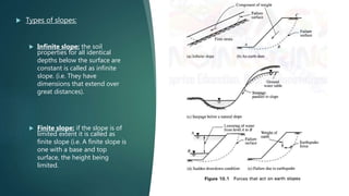
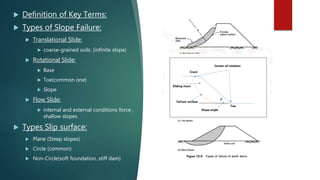
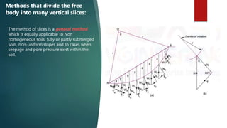
The document provides a comprehensive overview of various methods for slope stability analysis, highlighting the importance of assessing slope stability to prevent failures that could result in loss of life and property. It discusses the principles and applications of limit equilibrium and finite element methods, outlining their advantages and limitations in different soil conditions. The conclusion emphasizes the varying accuracy of these methods and the need for appropriate selection based on specific soil types and conditions.


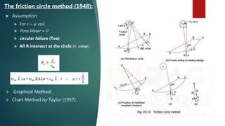
![A. Methods that consider the whole
free body:
Culmann’s methods:
Culmann (1866) considered a simple
failure mechanism of slope of
homogenous soil with plane failure
surface passing through toe of
slope.[2]
Stability analysis of finite slops:
𝐻𝑐 =
4𝑐′
𝑠𝑖𝑛𝛽. 𝑐𝑜𝑠𝜑′
𝛾[1 − cos(𝛽 − 𝜑′)
Allowable
Culmann’s method is suitable for
very steep slopes.](https://image.slidesharecdn.com/slopestabilityanalysismethods-200416205736/85/Slope-stability-analysis-methods-11-320.jpg)

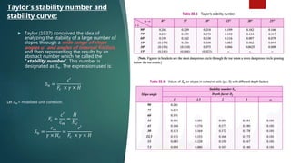
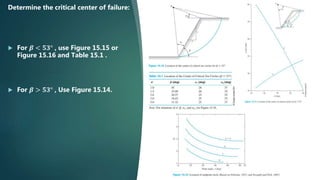
![ Steward et al. (2011) made hundreds of
runs using SLOPE/W to locate the
critical circles of slopes with 𝑐′
− 𝜑′
of
soil. According to this study, the failure
circles are mostly toe circles. However,
in a few cases, they can be midpoint
circles. Based on their study, a design
chart has been developed and is shown
in Figure 15.27. [13]
Analysis of Steward, Sivakuga,
Shukla, and Das (2011):](https://image.slidesharecdn.com/slopestabilityanalysismethods-200416205736/85/Slope-stability-analysis-methods-22-320.jpg)


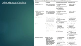

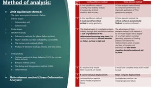
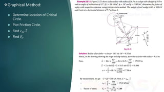
![Finite element method (Stress-Deformation Analyses):
As computer performance has improved, the application of FE in geotechnical
analysis has become increasingly common. These methods have several
advantages: to model slopes with a degree of very high realism (complex
geometry, sequences of loading, presence of material for reinforcement, action
of water, laws for complex soil behavior)
Strength Reduction Method:
In shear strength reduction method, soil shear strength is gradually decreased, by applying finite
element and finite difference programs as long as the first indications of failure appear. Safety factor is
defined as the ratio of real shear strength of soil to reduced shear strength. [9]
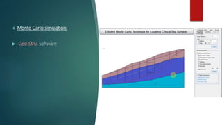
Monte Carlo simulation:
The mechanism is quite simple. The computer generates a random number between zero and one
from a uniform distribution. By knowing the cumulative distribution of the probability density function
for each variable entering into the design equation, the computer can pick up a unique value for each
variable.[10]](https://image.slidesharecdn.com/slopestabilityanalysismethods-200416205736/85/Slope-stability-analysis-methods-35-320.jpg)


![Geotechnical Engineering-II [Lec #26: Slope Stability]](https://cdn.slidesharecdn.com/ss_thumbnails/26-181125070353-thumbnail.jpg?width=640&height=640&fit=bounds)


![Geotechnical Engineering-II [Lec #27: Infinite Slope Stability Analysis]](https://cdn.slidesharecdn.com/ss_thumbnails/27-181125070251-thumbnail.jpg?width=640&height=640&fit=bounds)


![Geotechnical Engineering-II [Lec #28: Finite Slope Stability Analysis]](https://cdn.slidesharecdn.com/ss_thumbnails/28-181125070402-thumbnail.jpg?width=640&height=640&fit=bounds)


