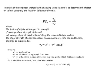
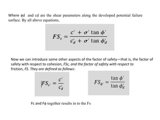
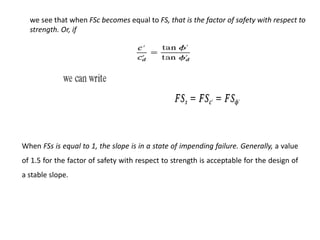
1) Slope stability is analyzed using the factor of safety, which is the ratio of resisting shear strength to driving shear stress. A factor of safety below 1.5 indicates instability.
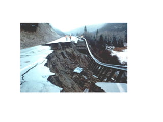
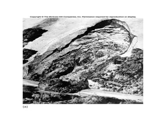
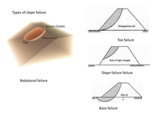
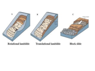
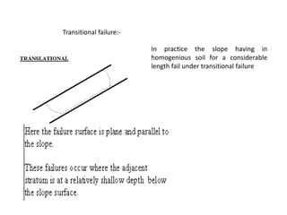
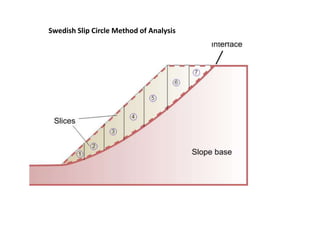
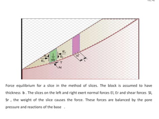
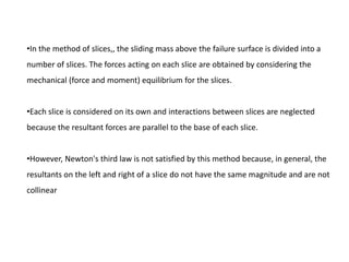
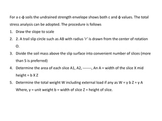
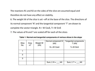
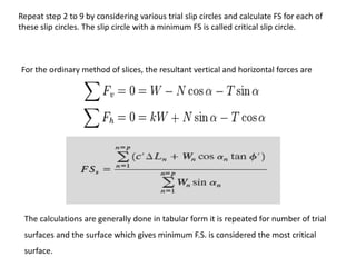
2) Common slope failure modes include rotational, toe, base, and transitional failures. The Swedish circle method divides a potential failure surface into slices to analyze stability.
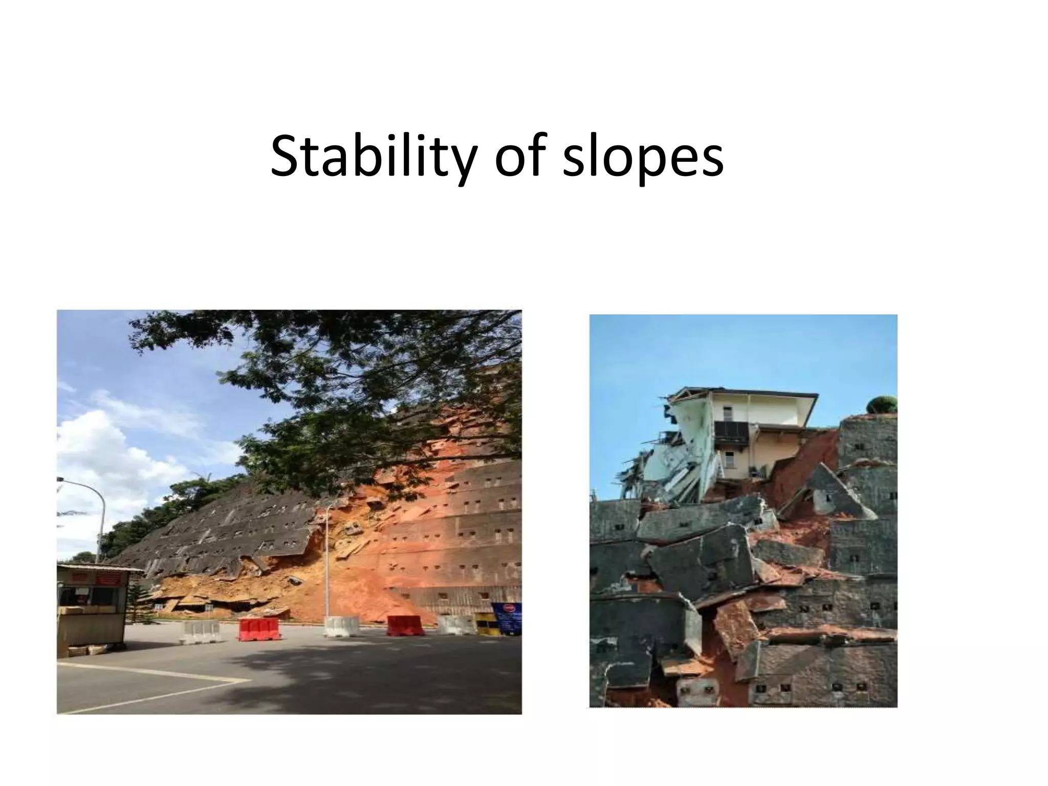
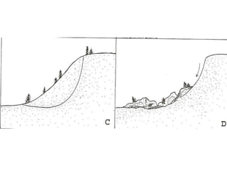
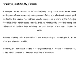
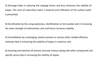
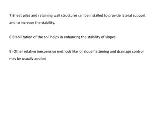
3) Factors that influence slope stability include soil properties, geometry, drainage conditions, and external loads. Various techniques can improve stability, such as flattening slopes, installing drainage, or adding retaining structures.


![Geotechnical Engineering-II [Lec #2: Mohr-Coulomb Failure Criteria]](https://cdn.slidesharecdn.com/ss_thumbnails/2-180930132603-thumbnail.jpg?width=640&height=640&fit=bounds)


![Geotechnical Engineering-II [Lec #28: Finite Slope Stability Analysis]](https://cdn.slidesharecdn.com/ss_thumbnails/28-181125070402-thumbnail.jpg?width=640&height=640&fit=bounds)