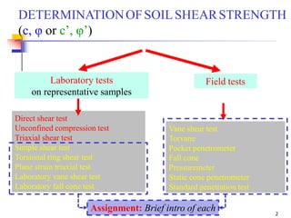
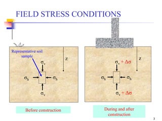
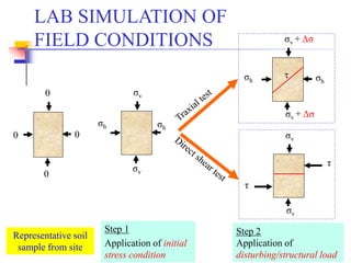
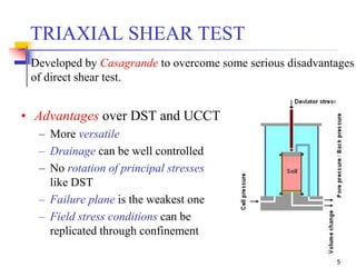
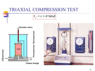
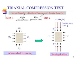
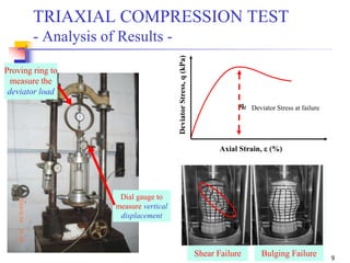
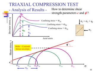
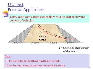
The document provides an overview of geotechnical engineering concepts focused on soil shear strength determination through various laboratory and field tests, including the triaxial shear test and its advantages over traditional methods. It outlines the procedure for conducting these tests, the interpretation of results, and practical applications in construction scenarios like earth dams and embankments. References to foundational texts in geotechnical engineering are included for further study.
![1
Geotechnical Engineering–II [CE-321]
BSc Civil Engineering – 5th Semester
by
Dr. Muhammad Irfan
Assistant Professor
Civil Engg. Dept. – UET Lahore
Email: mirfan1@msn.com
Lecture Handouts: https://groups.google.com/d/forum/geotech-ii_2015session
Lecture # 5
20-Sep-2017](https://image.slidesharecdn.com/5-180930132716/85/Geotechnical-Engineering-II-Lec-5-Triaxial-Compression-Test-1-320.jpg)

![Geotechnical Engineering-II [Lec #4: Unconfined Compression Test]](https://cdn.slidesharecdn.com/ss_thumbnails/4-180930132645-thumbnail.jpg?width=640&height=640&fit=bounds)
![Geotechnical Engineering-II [Lec #15 & 16: Schmertmann Method]](https://cdn.slidesharecdn.com/ss_thumbnails/15-181020124920-thumbnail.jpg?width=640&height=640&fit=bounds)
![Geotechnical Engineering-I [Lec #29: Soil Exploration - II]](https://cdn.slidesharecdn.com/ss_thumbnails/29-180924141840-thumbnail.jpg?width=640&height=640&fit=bounds)
![Geotechnical Engineering-II [Lec #27: Infinite Slope Stability Analysis]](https://cdn.slidesharecdn.com/ss_thumbnails/27-181125070251-thumbnail.jpg?width=640&height=640&fit=bounds)
![Geotechnical Engineering-I [Lec #19: Consolidation-III]](https://cdn.slidesharecdn.com/ss_thumbnails/19-180924141035-thumbnail.jpg?width=640&height=640&fit=bounds)
![Geotechnical Engineering-II [Lec #7: Soil Stresses due to External Load]](https://cdn.slidesharecdn.com/ss_thumbnails/7-180930132739-thumbnail.jpg?width=640&height=640&fit=bounds)

![Geotechnical Engineering-I [Lec #10: USCS]](https://cdn.slidesharecdn.com/ss_thumbnails/10-180923183613-thumbnail.jpg?width=640&height=640&fit=bounds)
![Geotechnical Engineering-I [Lec #17: Consolidation]](https://cdn.slidesharecdn.com/ss_thumbnails/17-180924140731-thumbnail.jpg?width=640&height=640&fit=bounds)


![Geotechnical Engineering-II [Lec #6: Stress Distribution in Soil]](https://cdn.slidesharecdn.com/ss_thumbnails/6-180930132732-thumbnail.jpg?width=640&height=640&fit=bounds)

![Geotechnical Engineering-II [Lec #17: Bearing Capacity of Soil]](https://cdn.slidesharecdn.com/ss_thumbnails/17-181123045836-thumbnail.jpg?width=640&height=640&fit=bounds)


![Geotechnical Engineering-II [Lec #28: Finite Slope Stability Analysis]](https://cdn.slidesharecdn.com/ss_thumbnails/28-181125070402-thumbnail.jpg?width=640&height=640&fit=bounds)


![Geotechnical Engineering-II [Lec #26: Slope Stability]](https://cdn.slidesharecdn.com/ss_thumbnails/26-181125070353-thumbnail.jpg?width=640&height=640&fit=bounds)
![Geotechnical Engineering-II [Lec #25: Coulomb EP Theory - Numericals]](https://cdn.slidesharecdn.com/ss_thumbnails/25-181123050611-thumbnail.jpg?width=640&height=640&fit=bounds)
![Geotechnical Engineering-II [Lec #24: Coulomb EP Theory]](https://cdn.slidesharecdn.com/ss_thumbnails/24-181123050536-thumbnail.jpg?width=640&height=640&fit=bounds)
![Geotechnical Engineering-II [Lec #23: Rankine Earth Pressure Theory]](https://cdn.slidesharecdn.com/ss_thumbnails/23-181123050516-thumbnail.jpg?width=640&height=640&fit=bounds)
![Geotechnical Engineering-II [Lec #22: Earth Pressure at Rest]](https://cdn.slidesharecdn.com/ss_thumbnails/22-181123050434-thumbnail.jpg?width=640&height=640&fit=bounds)


![Geotechnical Engineering-II [Lec #19: General Bearing Capacity Equation]](https://cdn.slidesharecdn.com/ss_thumbnails/19-181123045917-thumbnail.jpg?width=640&height=640&fit=bounds)
![Geotechnical Engineering-II [Lec #18: Terzaghi Bearing Capacity Equation]](https://cdn.slidesharecdn.com/ss_thumbnails/18-181123045854-thumbnail.jpg?width=640&height=640&fit=bounds)
![Geotechnical Engineering-II [Lec #14: Timoshenko & Goodier Method]](https://cdn.slidesharecdn.com/ss_thumbnails/14-181020124917-thumbnail.jpg?width=640&height=640&fit=bounds)
![Geotechnical Engineering-II [Lec #13: Elastic Settlements]](https://cdn.slidesharecdn.com/ss_thumbnails/13-181020124852-thumbnail.jpg?width=640&height=640&fit=bounds)
![Geotechnical Engineering-II [Lec #12: Consolidation Settlement Computation]](https://cdn.slidesharecdn.com/ss_thumbnails/12-181020124845-thumbnail.jpg?width=640&height=640&fit=bounds)
![Geotechnical Engineering-II [Lec #11: Settlement Computation]](https://cdn.slidesharecdn.com/ss_thumbnails/11-181020124840-thumbnail.jpg?width=640&height=640&fit=bounds)
![Geotechnical Engineering-II [Lec #9+10: Westergaard Theory]](https://cdn.slidesharecdn.com/ss_thumbnails/9-181020124827-thumbnail.jpg?width=640&height=640&fit=bounds)
![Geotechnical Engineering-II [Lec #8: Boussinesq Method - Rectangular Areas]](https://cdn.slidesharecdn.com/ss_thumbnails/8-181020124822-thumbnail.jpg?width=640&height=640&fit=bounds)
![Geotechnical Engineering-II [Lec #7A: Boussinesq Method]](https://cdn.slidesharecdn.com/ss_thumbnails/7a-181020124807-thumbnail.jpg?width=640&height=640&fit=bounds)
![Geotechnical Engineering-II [Lec #2: Mohr-Coulomb Failure Criteria]](https://cdn.slidesharecdn.com/ss_thumbnails/2-180930132603-thumbnail.jpg?width=640&height=640&fit=bounds)
![Geotechnical Engineering-II [Lec #1: Shear Strength of Soil]](https://cdn.slidesharecdn.com/ss_thumbnails/1-180930132556-thumbnail.jpg?width=640&height=640&fit=bounds)
![Geotechnical Engineering-II [Lec #0: Course Material]](https://cdn.slidesharecdn.com/ss_thumbnails/0-180930132420-thumbnail.jpg?width=640&height=640&fit=bounds)
![Geotechnical Engineering-I [Lec #28: Soil Exploration]](https://cdn.slidesharecdn.com/ss_thumbnails/28-180924141716-thumbnail.jpg?width=640&height=640&fit=bounds)


