Downloaded 35 times

![16
Transition Labeling Syntax
• Comments can be placed
anywhere
• All other sections must
remain in order shown
Enclosed in
/* */
Enclosed in
[ ]
Enclosed in
{ }
Preceded by
/](https://image.slidesharecdn.com/stateflowworkshop-171227121207/75/Simulink-Stateflow-workshop-16-2048.jpg)

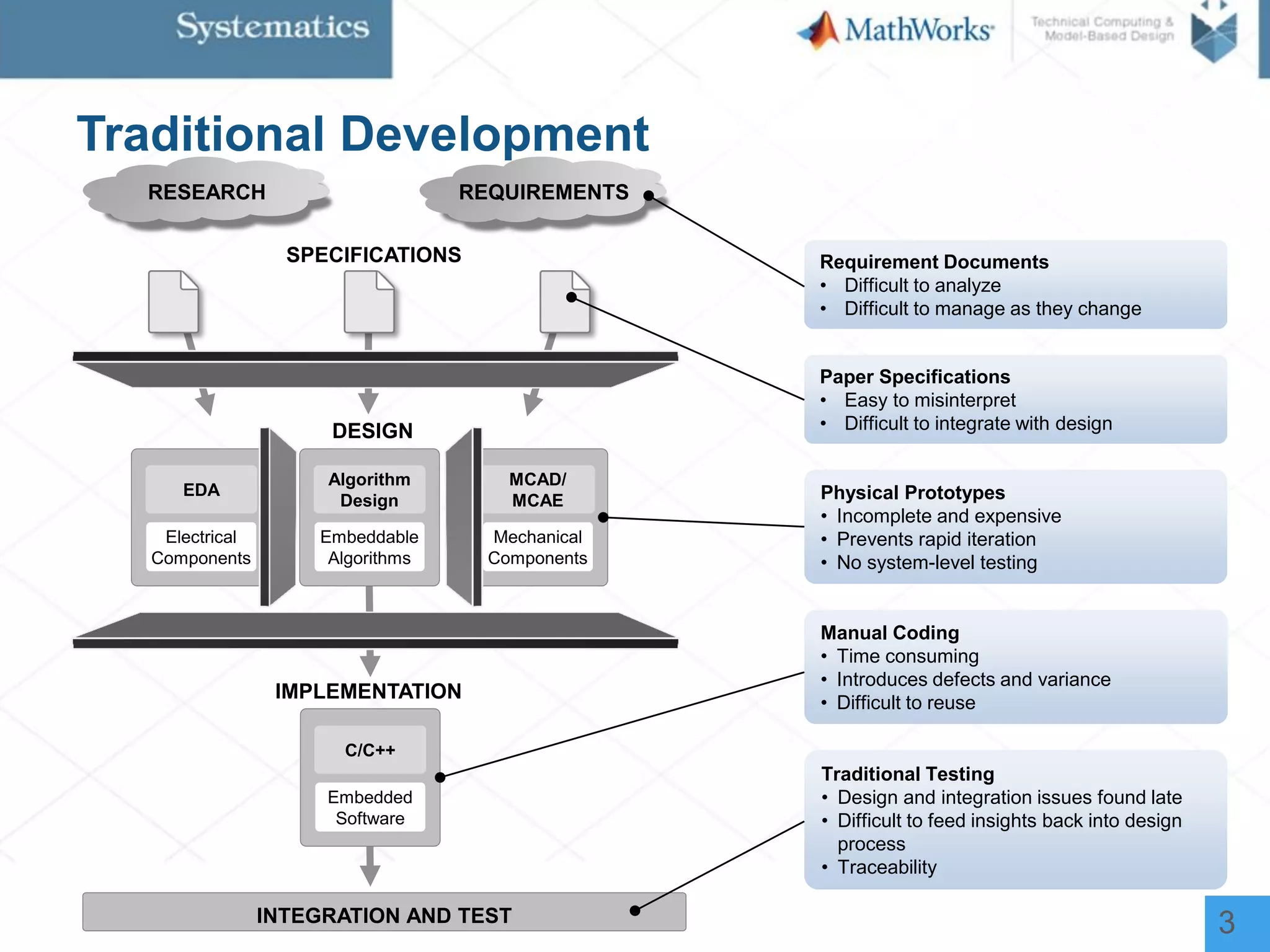
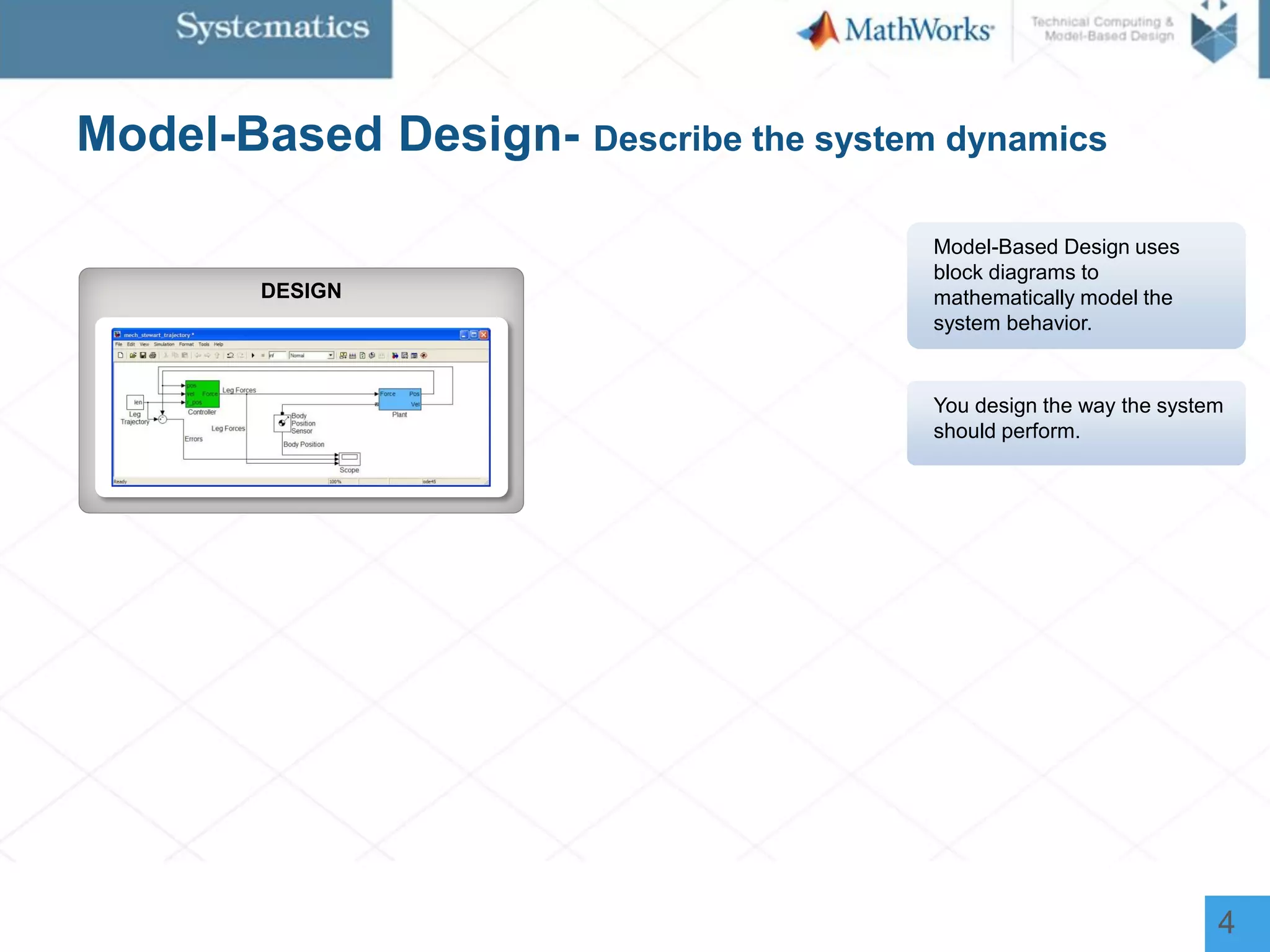
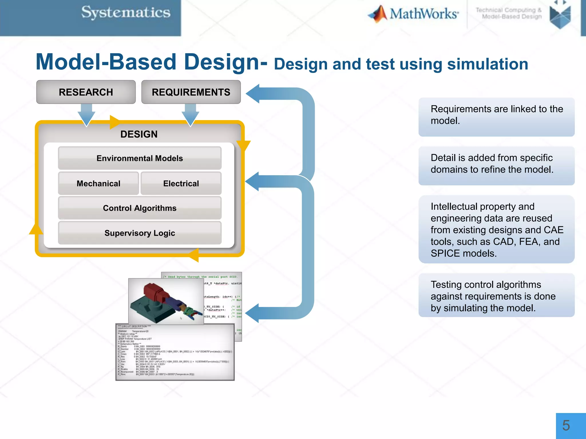
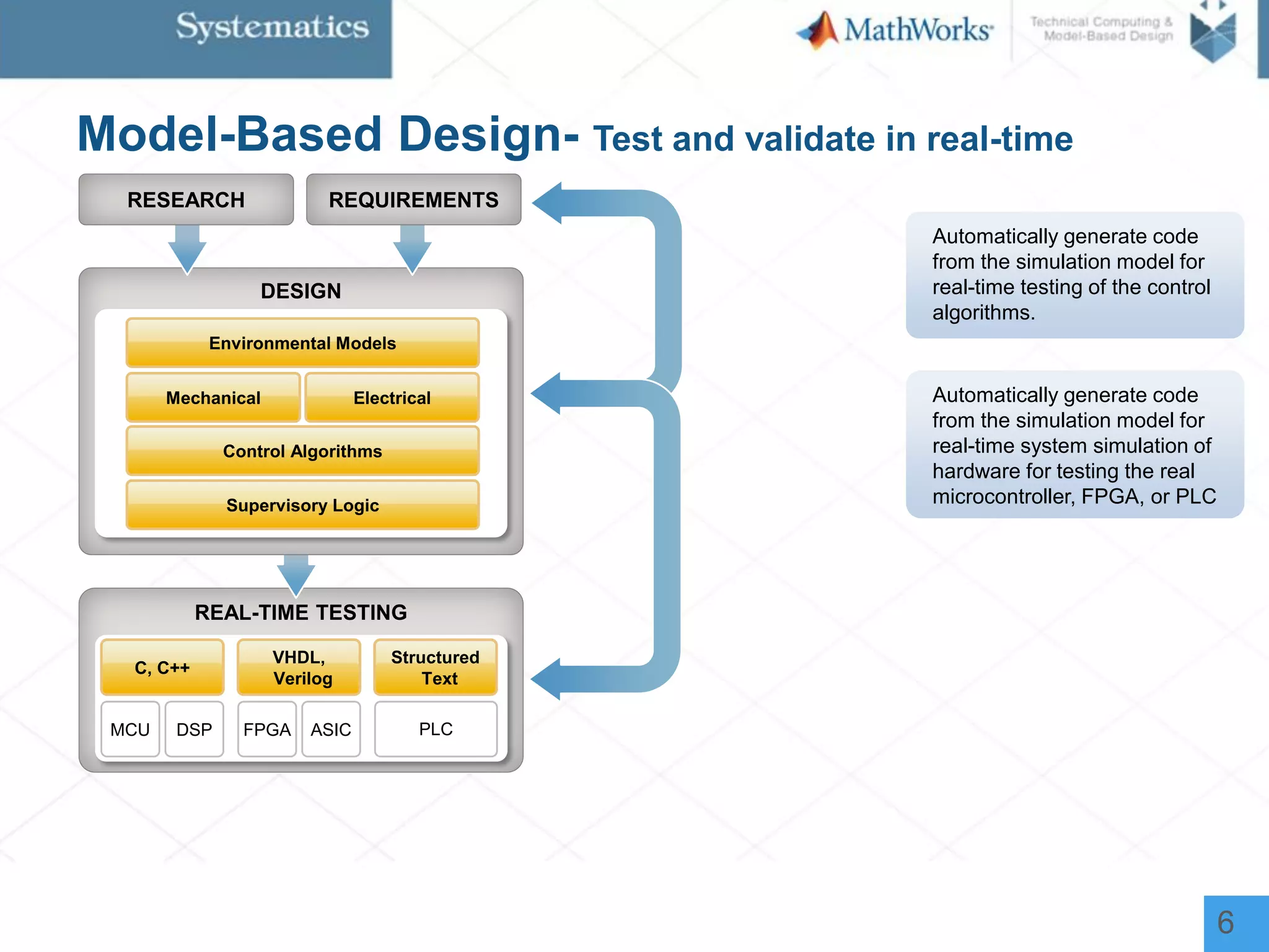
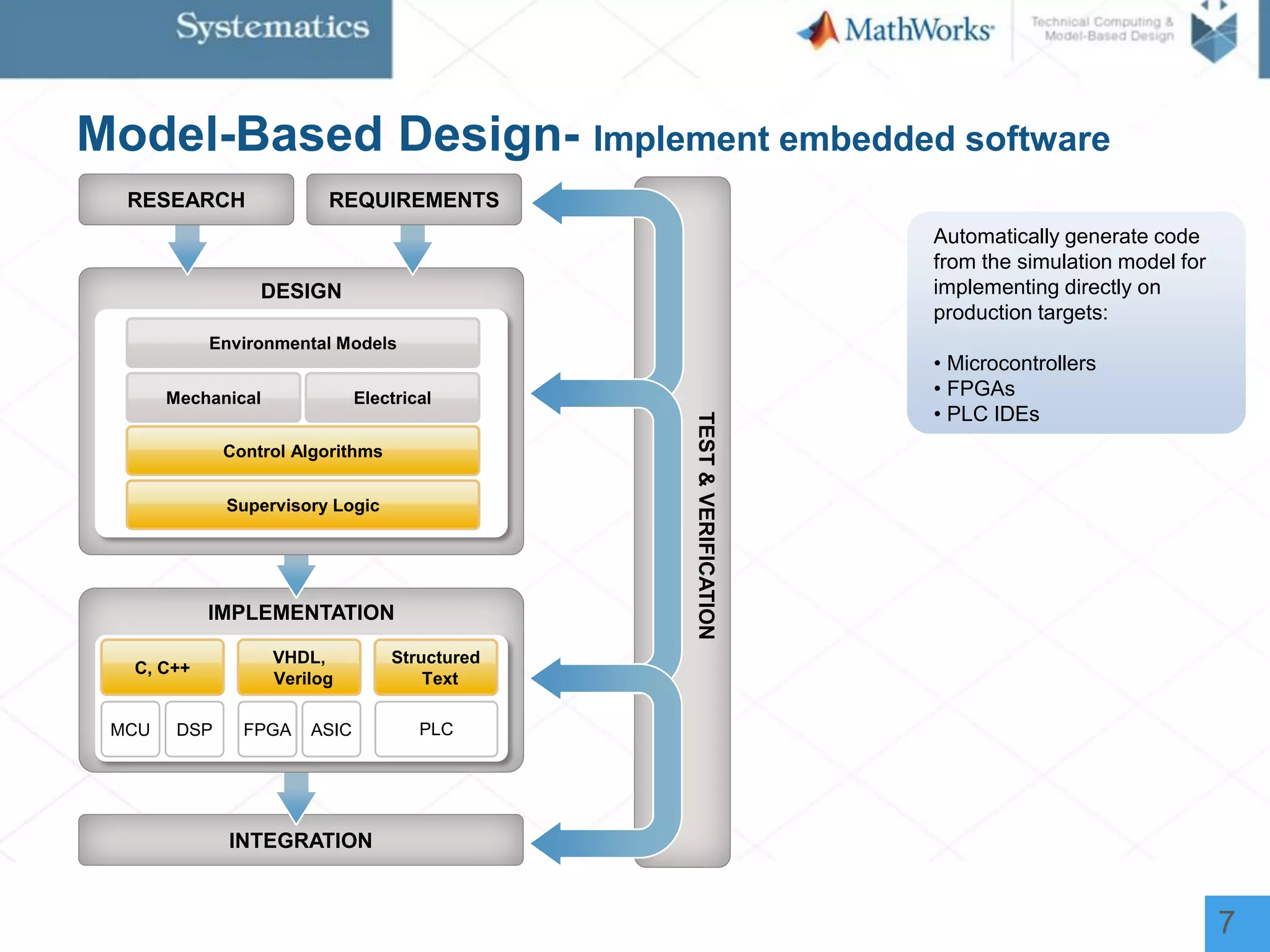
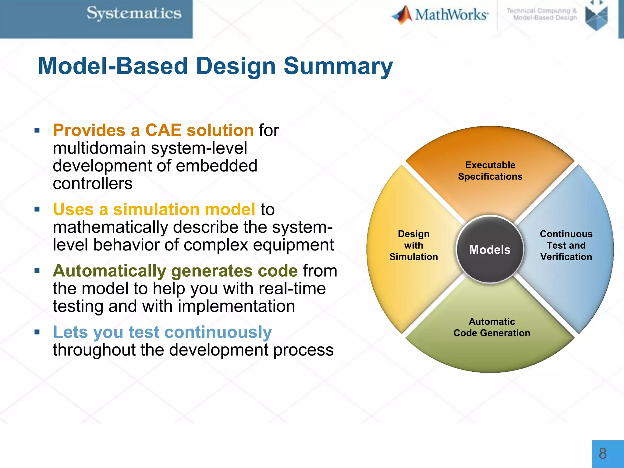
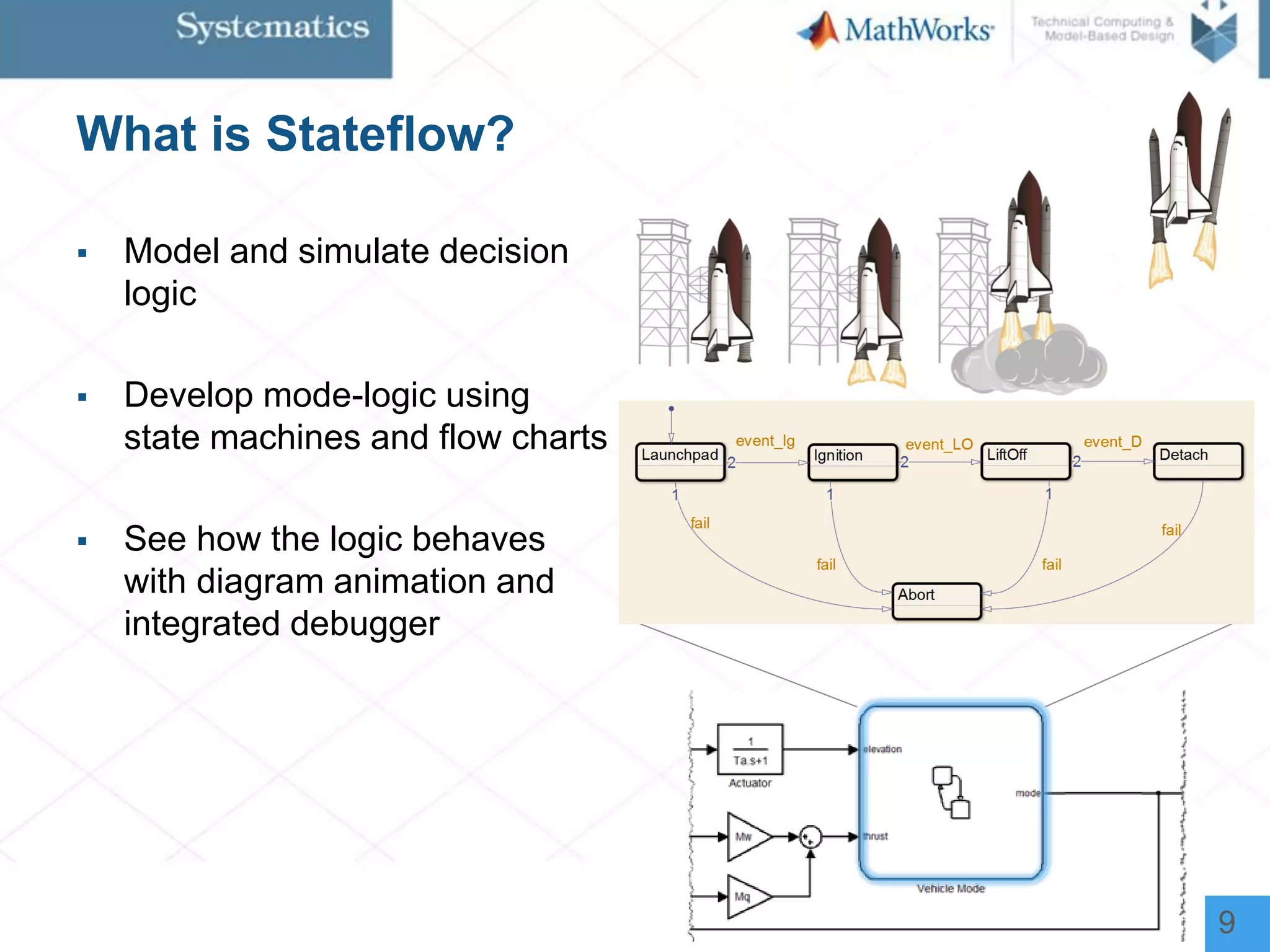
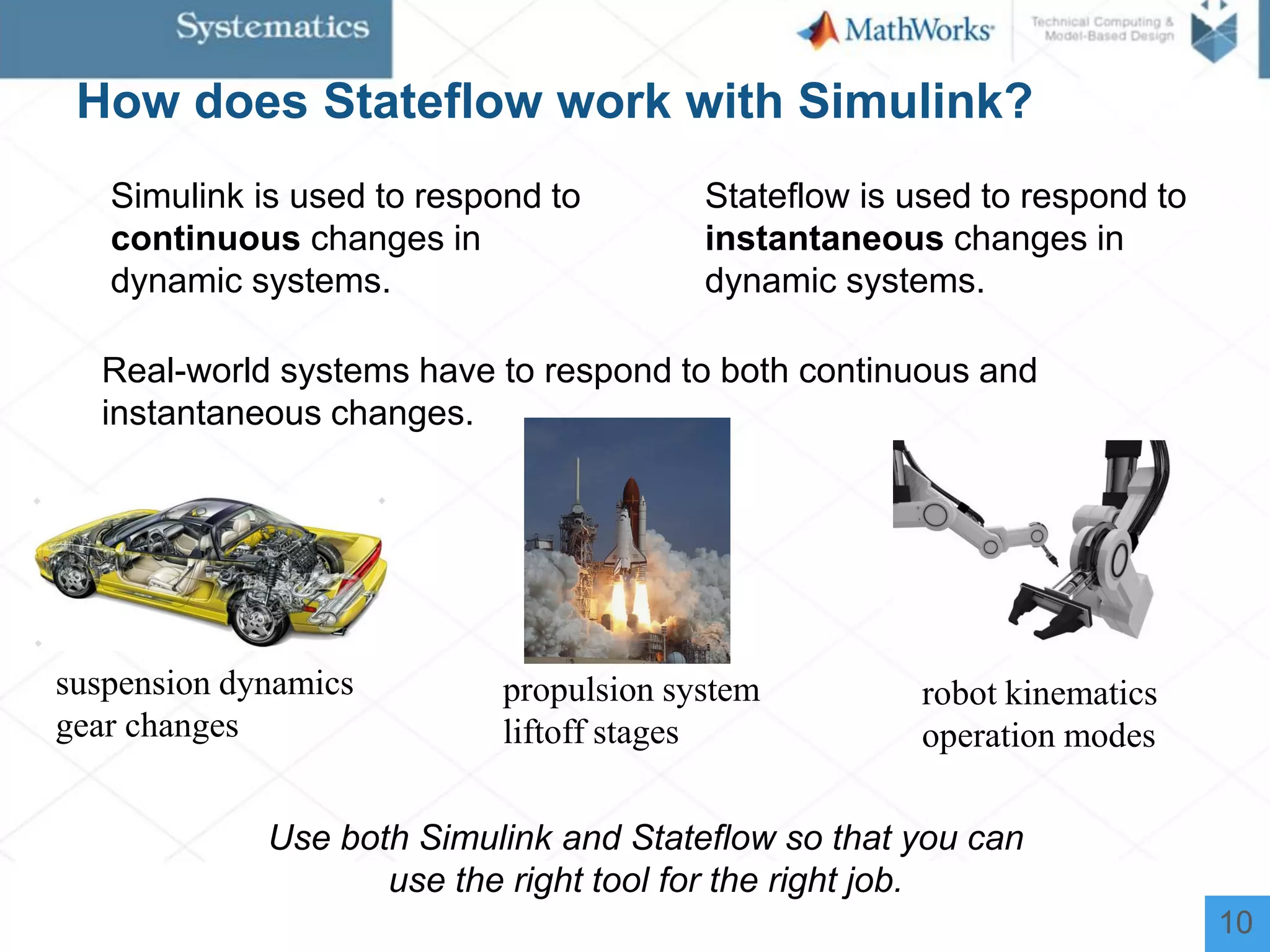
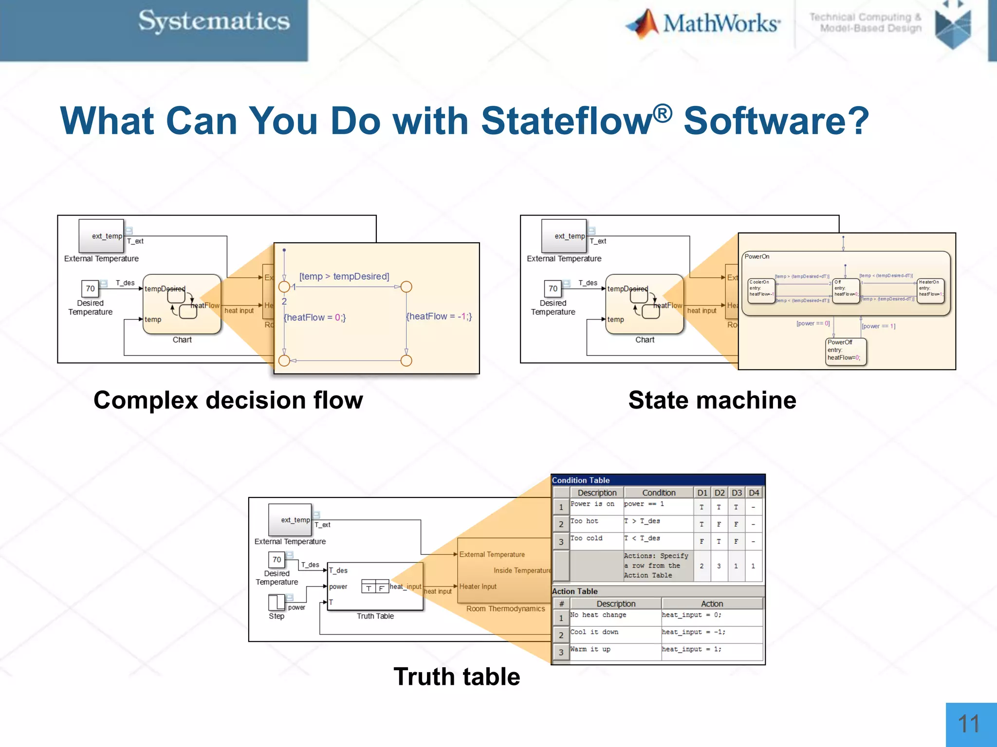
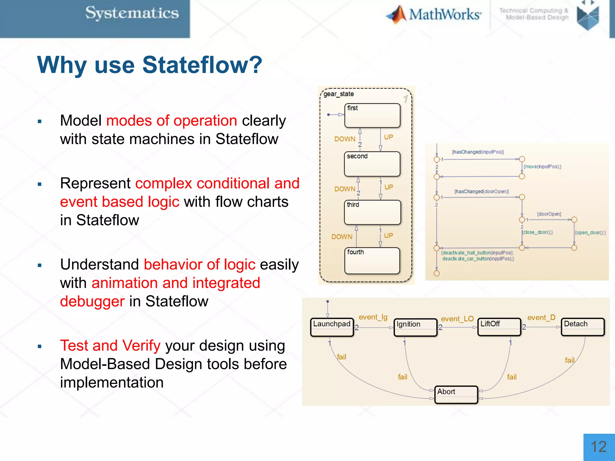
The document outlines a workshop on model-based design for system engineers, emphasizing the use of Stateflow and Simulink in designing, testing, and implementing embedded systems. It discusses the benefits of automated code generation, real-time testing, and continuous verification throughout the development process. Key features of Stateflow include modeling decision logic and using state machines and flow charts to represent complex logic behavior effectively.